HAL Id: hal-00707944
https://hal.archives-ouvertes.fr/hal-00707944
Submitted on 19 Jun 2012HAL is a multi-disciplinary open access
archive for the deposit and dissemination of sci-entific research documents, whether they are pub-lished or not. The documents may come from teaching and research institutions in France or
L’archive ouverte pluridisciplinaire HAL, est destinée au dépôt et à la diffusion de documents scientifiques de niveau recherche, publiés ou non, émanant des établissements d’enseignement et de recherche français ou étrangers, des laboratoires
Formalising Guidance for the CREWS Goal-Scenario
Approach to Requirements Engineering
Samira Si-Said, Colette Rolland
To cite this version:
Samira Si-Said, Colette Rolland. Formalising Guidance for the CREWS Goal-Scenario Approach to Requirements Engineering. European-Japanese Conference on Information Modelling and Knowledge Bases, 1998, Finland. pp.1-19. �hal-00707944�
CREWS Report Series 98
F
ORMALISINGG
UIDANCE FOR THECREWS G
OAL-S
CENARIOA
PPROACH TOR
EQUIREMENTSE
NGINEERINGS. Si-Saïd, C. Rolland
Université Paris 1 - Sorbonne C.R.I 90, rue de Tolbiac. 75013 Paris - France
email {sisaid, rolland}@univ-paris1.fr
Proceedings of the Eight European - Japanese Conference on Information Modelling and Knowledge Bases. May 25-29, Vamala, Finland.
FORMALISING GUIDANCE FOR THE
CREWS GOAL-SCENARIO APPROACH
TO REQUIREMENTS ENGINEERING
1
Samira Si-Said and Colette Rolland email {sisaid, rolland}@univ-paris1.fr
Université Paris-1 Sorbonne, CRI, 90, rue de Tolbiac, 75013 Paris, FRANCE
Abstract :Guidance plays a crucial role in requirements engineering (RE) as this task is both ill defined and highly intellectual. The guidance approach presented in this paper consists of supporting requirements engineers by a collection of enactable guidelines embodied in a computer environment. The key characteristics of the approach is its intention orientation. Guidance can be provided once the intention to be achieved has been elicited. Two kinds of guidance are proposed, step and flow guidance. The former supports the fulfilment of intentions whereas the latter helps in intention elicitation. The paper presents the two types of guidance, the corresponding guidelines and the Computer Aided Requirements Engineering (CARE) environment which supports their enactment. The approach is illustrated with the CREWS requirements engineering approach which elicits requirements through interleaved goal modelling and scenario authoring.
1. Introduction
In the ESPRIT CREWS project, we have proposed [Rol,98] an approach that combines a goal driven approach for Requirements Engineering (RE) with the use of scenarios. The total solution is in two parts. First, for a goal, scenarios are authored by the scenario author. Thereafter, the authored scenario is explored to yield goals which, in turn, cause new scenarios to be authored and so on.
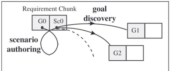
Our approach couples a goal and a scenario in a Requirement Chunk (RC) as a pair <G, Sc> where G is a goal and Sc is a scenario. The requirement chunk is the central part of the RE process which consists of repeating a two phases cycle composed of (1) scenario authoring and (2) goal discovery as illustrated in Figure 1.
1
The work presented in this paper is funded by the European Community within the framework of the ESPRIT LTR project CREWS (Cooperative Requirements Engineering With Scenarios) n°21903.
Requirement Chunk G0 Sc0 goal discovery scenario authoring G1 G2
Figure 1: Overview of the discovery process.
In the approach, scenario and goal modelling complement each other, thus avoiding the drawbacks of using each technique in isolation [Pot,97]. By combining goals and scenarios the approach aims at :
(a) facilitating the work of the domain expert by getting over the problem of the fuzzy nature of goals,
(b) contributing to the important question ‘where the goal originates from’ [Ant, 96] by helping discover goals,
(c) overcoming the difficulties encountered in concrete experiences of goal modelling ([Ant, 96], [Bub, 94], [Rol, 97]) by aiding in the task of goal reduction,
In order to fulfil these objectives we propose to support the RE process by enactable guidelines rules embodied in a computer environment to guide the requirements elicitation process through interleaved goal modelling and scenario authoring. The focus of this paper is on the generic guidance approach defined by us to support any RE process and its application to the CREWS approach.
Guidance plays a crucial role in the requirements engineering process ([Rol, 94], [Rol, 95]). This is due, first, to the nature of the task which is both ill defined and highly intellectual. Thus, guidance has to be far more knowledge-intensive than in other activity. The required support is based, for example, on suggestions on how to proceed in a certain situation, or on providing various ways to progress from a given situation to the next step in the process. It is clearly beyond the simple automated control of workflows of activities provided by most methods in practice and by software engineering environments. Second, it is difficult, if not impossible, for the RE process to progress without guidance. Requirements engineers need to be guided and advised, locally to handle the particular situation they are faced to, and globally, to monitor the flow of decisions they have to make. Our experiences with the goal driven approach embodied in the EKD method ([Bub, 94], [Kar, 98], [Lou, 97], [Rol, 97]) to several domains, air traffic control, electricity supply, human resource management, tool set development, show for example, that it is difficult for domain experts to perform goal modelling meaningfully without guidance. Locally they need help to reason about the goal they have in mind whereas globally, they require support to master the goal reduction process. Existing CASE tools supporting current information system engineering methods and software engineering centred software environments are unable to provide today the kind of heuristics and experience based guidance required in the early phases of system development. CASE tools help in capturing, storing and documenting information system products but do not support RE engineers in their elicitive engineering tasks [Mar, 93], [Hen, 94]. Process-centred software development environments essentially enforce the process performance that
Our guidance approach consists of supporting the RE engineers by a collection of enactable guidelines. This approach is suitable for large scale processes. Indeed, the two principles underlying the approach, namely, modularisation and reusability, allow the organisation of process knowledge and its integration during process enactment. The process knowledge is described as a collection of reusable guidelines. Each guideline results from the capitalisation of heuristics from experiences into a coherent and reusable component. These guidelines can be further be combined together in a meaningful and flexible way to support processes according to the RE engineers needs [Pli, 98].
The key characteristic of the approach is its intentional orientation and the strong association between the intention and the situation in which the intention can be achieved. Guidance can be provided once the intention to be achieved, for example ‘to author a scenario’ has been identified. Two kinds of guidance are proposed, step and flow guidance. The former supports the fulfilment of intentions (to guide scenario authoring for example) whereas the latter helps in intention identification (what to achieve next to scenario authoring). Both are driven by guidelines, step and flow guidelines respectively. The guidance approach is presented in section 2 and exemplified with the guidelines driving the CREWS goal-scenario approach. The approach is implemented in a process centred CARE environment called MENTOR presented in section 3. In section 4 we illustrate the CREWS guided process with an example. Finally some conclusive remarks are made in section 5.
2. The guidance approach
We assume RE processes to be intention-oriented and therefore guidance assume that there is an intention to be achieved and that help is needed to fulfil it. Our approach proposes two kinds of help (a) help in the satisfaction of an intention and, (b) help in selecting the next intention to make the process proceed. We refer to the former as step guidance and to the latter as flow guidance. In the rest of this section we introduce our intention-oriented view of RE processes and develop step and flow guidance respectively.
3. Our RE process modelling view
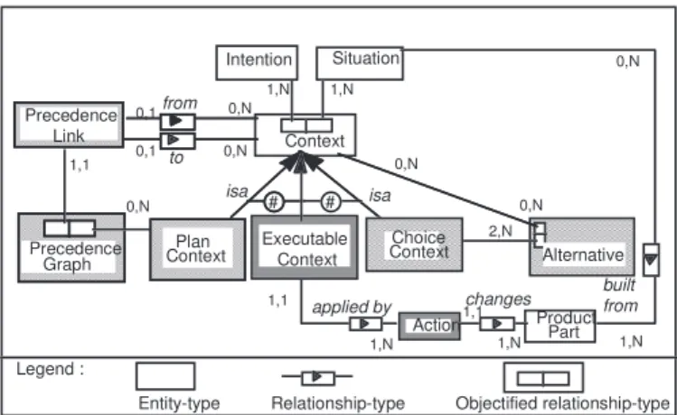
We consider that RE processes are essentially intentional. At any moment, the requirements engineer has an intention, a goal in mind that he/she wants to fulfil. To take into account this characteristics, we have chosen to emphasise the contextual aspect of RE intentions ([Rol,93], [Rol,95]). Our process modelling view strongly couples the context in which the intention is raised and the intention itself. It makes the notion of a context, the coupling of a situation and the intention associated to it, central to process modelling (see Figure 2) .
We distinguish three types of contexts : executable contexts, plan contexts, and choice contexts. This distinction is necessary to handle different granularity levels of contexts. A situation exists at different levels of granularity. Furthermore, intentions have consequences which differ from one granularity level to another. A complete understanding of the notion of a context can thus be gained by articulating the consequences of satisfying the intention of a context on the product under development. We present here a brief description of each of the three contexts.
Legend :
Entity-type Relationship-type Objectified relationship-type 2,N 1,N 0,1 0,N Alternative Situation Context built from 1,N 0,1 0,N 0,N from to 1,1 0,N Precedence Graph Executable Context
Action Product Part
changes applied by 1,1 1,N 1,N 1,1 1,N 0,N Plan Context # isa isa 0,N Choice Context # Intention Precedence Link
Figure 2 :Overview of the process modelling view
Executable context
At the lowest level, the RE process can be seen as a set of transformations performed on the product under development. Each transformation results from the execution of a deterministic action which, in turn, is a consequence of an intention achieved by a certain context. This leads to the introduction of the concept of an executable context.
An executable context expresses the realisation of an intention by an action. This action modifies the product under development and eventually generates a new situation subject to new intentions.
Choice context
During requirements engineering processes, engineers may have several alternative ways to fulfil an intention. In order to represent such situations, we introduce the specialisation of context into choice context. A choice context allows the exploration of alternative solutions represented in turn as contexts. Each alternative is associated to a set of supporting or objecting statements named arguments which are combined into choice criteria to support the selection of the appropriate alternative.
Plan context
The last kind of context corresponds to intentions which need to be decomposed into more detailed ones. A plan context is an abstraction mechanism by which a context viewed as a complex issue can be decomposed in a number of sub-issues. Each sub-issue corresponds to a sub-intention working on a sub-situation.
The ordering of the component contexts, within a plan, is defined by a graph named precedence graph Figure 2. There is one graph per plan context. The nodes of this graph are contexts while the links -called precedence links- define either the possible ordered transitions between contexts or their possible parallel enactment.
The guidelines supporting the RE process will be presented as hierarchies of contexts (see [Rol, 95] for examples). This vision allows the description of flexible, reusable and adaptable processes. Indeed, describing processes at the intentional level releases them from the over automation that we find at the action level. Additionally representing the intentional aspect of processes facilitates their comprehension and thus, their adaptation and reuse.
3.1. Step and flow guidance
As the RE process is intention-oriented, the requirements engineer is repeatedly concerned with two issues : (a) how to fulfil the intention he/she has currently in mind and (b) how to select the next intention to make the process proceed. In other words, an intentional process can be looked upon as a repeated performance of a two-phases cycle comprising :
• the Achieve phase aiming at the fulfilment or the realisation of a given intention in a given context, and
• the Progress phase for selecting the next intention to achieve. If guidance is provided, it must therefore support (see Figure 3)
(a) the achievement of an intention in its context and,
(b) to help in selecting the next intention in its context (see Figure 3). We refer to the former as step guidance and to the latter as flow guidance.
Step guidance helps mastering the complexity of processes due to the multiplicity of the possible ways for resolving an issue, whereas flow guidance limits the difficulties related to the ‘maze effect’ : there are multiple possible roads for progressing in the process from one step to another and help is required to choose the appropriate one.
Flow guidance to progress in the process by selecting <s2, i2> for the next
step
Flow guidance to progress in the process by selecting <s2, i2> for the next
step Step guidance to achieve intention i1 in situation s1 Step guidance to achieve intention i1 in situation s1 <situation s1, intention i1> <situation s2, intention i2> step1 step2 stepn Figure 3: Step and flow guidance
These two forms of guidance are governed by guidelines which explicit the way in which engineers will be guided. Therefore, there are two types of guidelines : step guidelines and flow guidelines.
We first present the way guidelines are structured and described in section 2.3. We develop with more details step and flow guidelines in section 2.4.
3.2. Guideline structure and description
A guideline is defined as ‘a set of indications on how to proceed to achieve a goal or perform an activity’ (Robert, 1984).
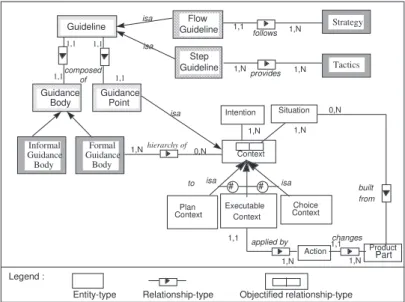
Formally as shown in Figure 4, a guideline is composed of two parts : a guidance point and a guidance body.
A guidance point is a context formed as a pair <situation, intention> which expresses a situation in which guidance can be provided to support the fulfilment of an intention. The pair <(Goal), Author a scenario> is an example of guidance point. The intention is to ‘Author a scenario’. The scenario aims at illustrating the system goal which constitutes the situation of the context. The intention is applicable to any ‘Goal’ existing in the product.
The guidance body explicitly expresses the way to provide guidance. It can be either informal or formal (see Figure 4). It is informal when the contents of the guideline is described informally using examples, and/or unstructured text. In this case guidance is simply provided by displaying the guidance body. When the guidance body is formal, its contents is expressed as hierarchies of contexts and guidance is provided through the automated guideline enactment performed by the guidance engine of the MENTOR environment. (For sake of readability the context model has been simplified. See figure 2 for the complete view).
Legend :
Entity-type Relationship-type Objectified relationship-type 1,N Situation Context built from 1,N to Executable Context
Action Product Part
changes applied by 1,1 1,N 1,1 1,N Plan Context # isa isa 0,N Choice Context # Intention Guideline GuidelineFlow
composed of Step Guideline 1,1 Guidance Body Guidance Point Informal Guidance Body Formal Guidance Body isa hierarchy of Strategy follows 1,N Tactics provides 1,N 1,1 1,N 1,1 1,1 1,1 isa isa 0,N 1,N
Figure 4: Guideline structure
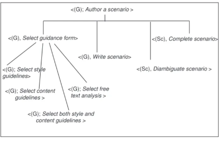
Figure 5 is an example of the formally expressed guideline to support the intention ‘Author a scenario’. Within the CREWS project we assume scenarios to be textual and use authoring rules to provide style and content guidelines as well as linguistic devices for analysis, disambiguation and completion. The linguistic devices are based on case grammar and case patterns. Details can be found in [Ben, 98].
The guideline is a plan context suggesting 4 steps to « Author a scenario » namely:
1. choose the form of guidance desired. Indeed the requirements engineer has the possibility to use style guidelines, contents guidelines, both of them or use free text analysis during scenario authoring. This is expressed in the choice context (<(G), Select guidance form>), 2. write the scenario being guided by the selected guidance form (<(G), Write scenario>), 3. disambiguate the resulting scenario (<(Sc), Disambiguate scenario>),
<(G); Select style
guidelines>
<(G); Select content
guidelines >
<(G); Select both style and
content guidelines >
<(G); Select free
text analysis >
<(G); Author a scenario >
<(G), Select guidance form> <(Sc), Complete scenario>
<(Sc), Diambiguate scenario > <(G), Write scenario>
Figure 5 : An example of a step guideline
All guidelines have the same structure and are either informally or formally described. However, they have different semantics depending on their type. We detail flow and step guidelines in the next section.
3.3. Step and flow guidelines
3.3.1. Step guidelines
A step guideline helps achieving an intention raised in a given situation. A step guideline is
associated to a step guidance point, step point in short. A step point spi is a couple (situationi,
intentioni) expressing that a requirements engineer focuses on a product part (the situation)
with some intention in mind. The situation refers to some part of the product under development (i.e. the requirements specification) whereas the intention is a sub-type of the achieve macro-intention (see section 2.2).
The set of step points represent all situations in which guidance can be provided. In order to identify the guidance points we need both the identification of a set of product parts P, and a set of related intentions I. The set of guidance points will be the set of all meaningful combinations from P*I.
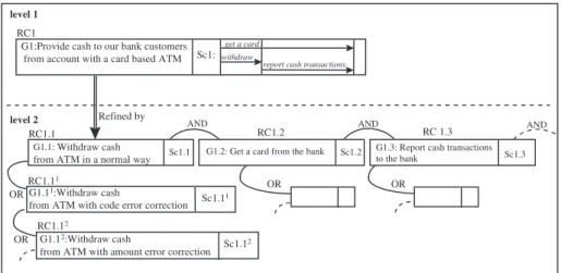
Let us construct the step points for the CREWS goal-scenario approach. Figure 6 presents an example of the product generated by the CREWS process. The basic block of the approach is the notion of a requirement chunk defined as a couple <G, Sc> where G is a goal and Sc a scenario. RC1 is an example of requirement chunk having ‘Provide cash to our bank customers from ATM’ as a goal and Sc1 as a scenario which concretises the goal. Sc1 is a message trace diagram [Rum, 91] comprising three interactions among agents, ‘Get a card’ (customer/bank), ‘Withdraw cash’ (customer/ATM) and ‘Report cash transactions’ (ATM/bank).
RC1.1 AND RC1.2 AND RC 1.3 G1.1: Withdraw cash
from ATM in a normal way Sc1.1 G1.11:Withdraw cash
from ATM with code error correction Sc1.1 1 RC1.11
RC1.12
Refined by
G1.12:Withdraw cash
from ATM with amount error correction Sc1.1 2 OR
OR
level 1
level 2
G1:Provide cash to our bank customers from account with a card based ATM Sc1: RC1
withdraw
Sc1.3 G1.3: Report cash transactions to the bank
AND G1.2: Get a card from the bank Sc1.2
OR OR
get a card
report cash transactions
Figure 6 : Example of a requirement chunk hierarchy
Requirements chunks are related to one another in three different ways through AND, OR and Refinement relationships. The composition and alternative relationships lead to an OR/AND structure between requirement chunks whereas the refinement relationship is used to describe requirement chunks at different levels of detail. For example in Figure 6 RC1 is refined by a
number of ANDed requirements chunks2 RC1.i, among which are the three complementary
requirement chunks RC1.1, RC1.2 and RC1.3 to respectively ‘Withdraw cash from ATM in a
normal way’, ' Get a card from the bank’ and ‘Report cash transactions to the bank’. These
three RCs are necessary to fulfil the RC1 goal ' Provide cash to our customers from ATM'.
Each of the RC1.i may have alternatives; for example RC1.1, RC1.11 and RC1.12 are
alternative ways of using the ATM to support the goal ' Withdraw cash from the ATM'.
From the CREWS product description introduced in Figure 6 we can identify five different product parts composing P, namely :
• Requirement chunk (RC) • Goal (G)
• Composition structure (ANDs), • Alternative structure (ORs) • Refinement structure (Rs).
Complementarily, we have identified two intentions. These are : • Author : for eliciting a scenario
• Discover : for eliciting a goal.
From the set of generated guidance points we select the following :
2
• <(G), Author scenario> • <(G) ; Discover goals>
• <(RC), Discover goals ANDed to RC’s goal > • <(RC), Discover goals ORed to RC’s goal > • <(RC), Discover goals Refined from RC’s goa l >
The body of a step guideline <(S), I> provides requirements engineers with a tactics to support the achievement of the intention I. By opposition to a strategy a tactics is concerned with the way of resolving an intention raised in the process. A step guideline may offer several alternative tactics to achieve the intention. The more is the diversity of tactics proposed to achieve the guideline intention, the better is the flexibility and efficiency of the guidance provided. For example, the step guideline already presented in Figure 5 proposes four different tactics to help the requirements engineer writing a scenario concretising a given goal : using style guidelines, using content guidelines, using content and style guidelines and using free text analysis.
3.3.2. Flow guidelines
A flow guideline provides support to progress from one guidance step to another under a strategy of requirements engineering.
A strategy - generally opposed to tactics- is concerned with the way to progress in a process. A strategy is domain specific. In the software engineering and information system engineering domains, we can find a set of common design strategies like the Top down, Bottom up, Inside-out strategies [Bat, 92].
As sketched in Figure 7 flow guidance is strategical whereas step guidance is tactical. Both are intentional, but the later helps to "Achieve" an intention whereas the former helps to "Progress" in the process performance. Moreover, a step guidance results in product transformation whereas flow guidance gives rise to a new step guidance point selection.
How to progress from step point
<Si, Ii> ?
step point <Sii,Ii>
Strategy 1 Strategy 2
Strategy n
How to achieve intention I ?
Tactics 1 Tactics 2 Tactics n
Strategic Guidance Tactical Guidance
step point <S, I>
step point <Sj, Ij>
step point <Sk, Ik>
Figure 7 : Strategical versus Tactical guidance
A flow guideline is associated to a flow guidance point, flow point for short. A flow point fpi
is a couple (situationi, intentioni) which expresses that the requirements engineer wants to
progress in the RE process (intentioni) from a given situation (situationi). The intention is a
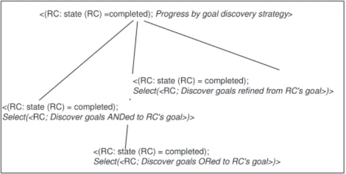
sub-type of the Progress macro-intention whereas the situation refers to the state of the product part. The couple <(RC :state(RC)=completed), Progress by goal discovery strategy>
is an example of flow point which associates the intention of progressing using a goal discovery strategy when a requirement chunk (RC) has been completed.
The body of a flow guideline is expressed using the same notation introduced in section 2.3. It is a hierarchy of contexts having the flow point as its root. The enactment of a flow guideline supports the requirements engineer in the selection of a new step point.
The body of the flow guideline associated to the flow point introduced above is shown in Figure 8. It describes how to progress after the completion of a requirement chunk RC using a goal discovery strategy.
<(RC: state (RC) =completed); Progress by goal discovery strategy>
<(RC: state (RC) = completed);
Select(<RC; Discover goals ANDed to RC's goal>)>
<(RC: state (RC) = completed);
Select(<RC; Discover goals ORed to RC's goal>)>
<(RC: state (RC) = completed);
Select(<RC; Discover goals refined from RC's goal>)>
Figure 8 :An example of flow guideline
The context in Figure 8 is a choice context with three alternatives. Each of the alternatives proposes the selection of a new step point in order to discover goals respectively ANDed, ORed to and Refined from the RC’s goal.
Every flow guideline corresponds to a possible guidance flow. The identification of flow points can be done in two steps :
• first, the set of strategies needs to be identified. Let S be this set.
• second, the set of targets, T, and their states, states(T) of all guidance points has to be identified.
The target is the product part resulting from the transformation performed by the point guideline. For instance, for the guidance point, <(G), Author a scenario> the target is the requirement chunk RC and the target state is state(RC)=completed.
The set of flow guidelines is the meaningful sub set obtained from T×S. It expresses the possible transitions between the step points using the several identified strategies. The example depicted in Figure 8 expresses the possible transitions from the guidance step point <(Goal), Author a scenario> using the goal discovery strategy.
The CREWS goal-scenario approach is based on three strategies, namely (a) the scenario-based strategy
(b) the goal discovery strategy (c) the goal analysis strategy
(a) and (c) are applicable when a goal has been elicited whereas (b) is valid when a requirement chunk is completed i.e. when a goal is elicited and the corresponding scenario is authored.
There are two noteworthy target states corresponding to the completion of a requirement chunk (state(RC)=completed) and the elicitation of a new goal (state(goal)=elicited). From the set of generated flow points, we have selected the three following ones:
• <(RC : state(RC)=completed), Progress by goal discovery strategy> • <(G : state(G)=elicited), Progress by goal analysis strategy> • <(G : state(G)=elicited), Progress by scenario-based strategy>
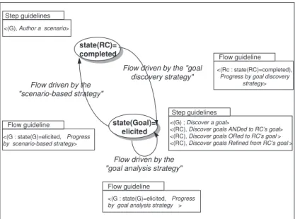
Figure 9 sums up the way guidance is provided to support the requirements elicitation process following the CREWS approach.
state(RC)= completed
state(Goal)= elicited
Flow driven by the "goal discovery strategy" Flow driven by the
"scenario-based strategy"
Flow driven by the "goal analysis strategy"
<(G) ; Discover a goal>
<(RC), Discover goals ANDed to RC’s goal> <(RC), Discover goals ORed to RC’s goal > <(RC), Discover goals Refined from RC’s goal > <(G), Author a scenario>
Step guidelines Step guidelines
<(Rc : state(RC)=completed),
Progress by goal discovery strategy> Flow guideline <(G : state(G)=elicited, Progress by scenario-based strategy> Flow guideline <(G : state(G)=elicited, Progress
by goal analysis strategy > Flow guideline
Figure 9 : Visualising guidance provided for the CREWS approach
The process flow is visualised using a transition graph. The nodes of the graph correspond to product states resulting from the use of step guidelines. The edges represent the three possible flow strategies, each being supported by a flow guideline.
The graph illustrates the alternance of goal discovery and scenario authoring in the CREWS approach. The latter is supported by one step guidance (<(G), Author a scenario>) whereas the former may be achieved in four different ways using the following guidelines: <(G) ; Discover a goal>, <(RC), Discover goals ANDed to RC’s goal >, <(RC), Discover goals ORed to RC’s goal >, <(RC), Discover goals Refined from RC’s goal >.
3.4. Guidance enactment
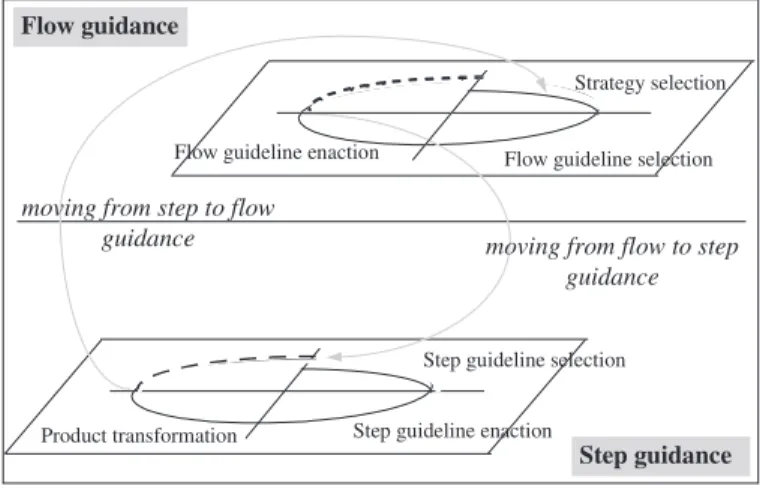
Guidance of RE processes is obtained by the enactment of guidelines. The two types of guidance are performed in turn to provide continuous support to the RE engineers. To illustrate the enactment, we adopt a spiral view as depicted in Figure 10.
Requirements engineering proceeds by the repeated use of the following cycle: - choose a step point,
- enact the corresponding step guideline, - select the next step point.
The selection of the next step point is supported by the flow guidelines. The two inter-linked forms of guidance are viewed as two intertwined spirals (see Figure 10).
Flow guidance
Step guidance moving from flow to step
guidance moving from step to flow
guidance
Strategy selection
Flow guideline selection Flow guideline enaction
Step guideline selection
Step guideline enaction Product transformation
Figure 10 : A view of guidance enactment
Enactment of flow guidance is viewed as a progression through the four quadrants of a spiral. During the first quadrant, it is suggested that the RE engineer could select a strategy from a set of suggested strategies. The selection of a strategy will lead to the selection of a flow point. The second quadrant consists of retrieving the flow guideline to support the engineer in the application of the strategy.
The third quadrant aims at enacting the flow guideline to select a step point.
The fourth quadrant aims at moving to the first quadrant of the lower level, intertwined spiral. This is to provide guidance in the enactment of the selected step point.
Enactment of step guidance, is also viewed as a progression through the four quadrants of a spiral.
In the first quadrant, the guideline associated with the selected step point is identified.
The second quadrant aims at the enactment of the corresponding step guideline. This results in the identification of executable contexts.
The third quadrant transforms the product by executing the executable contexts obtained in the second quadrant.
Aided Requirements Engineering (CARE) environment (section 3).
4. A process centred CARE environment
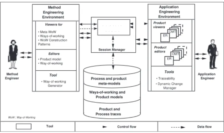
Guidelines are embodied in a software environment called MENTOR witch supports their automated enactment. Figure 11 gives an overview of the different components of the Computer Aided Requirements Engineering (CARE) environment MENTOR. It provides guidance to both method engineers and application engineers. In this short overview of MENTOR we limit ourselves to the later. A detailed presentation can be found in [Sis,96]. As shown in Figure 11, the environment is organised in four main components :
- the repository to store both ways-of-working and products,
- the method engineer environment for guiding method engineers in the construction of ways-of-working,
- the application engineer environment for guiding application engineers using ways-of-working,
- the guidance mechanism composed of the guidance engine as the kernel for the
whole CARE environment, and the session manager to co-ordinate access to all tools.
• The repository uses the O2 O.O.D.B.M.S. to store and manage data.
As shown in Figure 11., it is structured in three levels :
- the level corresponding to the implementation of both process and product meta-models as O2 classes.
- the model level corresponding to ways-of-working and product models related to different methods.
ν the work space level, composed of ways-of-working and products under development.
Session Manager Method Engineering Environment Guidance E ngine
Tool Control flow Data flow Method
Engineer
Application Engineer
Process and product meta-models Ways-of-working and Product models Product and Process traces Product viewers Product editors • Traceability • Dynamic Change Manager ER OMT ER OMT Viewers for • Meta WoW • Ways-of-working • WoW Construction Patterns Editors • Product model • Way-of-working • Way-of-working Generator Tool Tools WoW : Way-of-Working Application Engineering Environment
Figure 11: MENTOR : general architecture
• The Application engineering environment includes a set of specific graphical product editors and product viewers to develop RE specifications. A traceability tool and a process change manager are also available.
A product viewer allows a RE engineer to display the current state of a product in a window whereas a product editor provides him means to directly modify the product under development (in the current version of the prototype, tools are available for ER and static OMT specifications, these can easily be extended).
The traceability tool offers means for keeping track of product and process traces. The generated trace can be used for documentation purposes but can also be used as the raw material necessary for later improvement of ways-of-working.
The process change manager aims at keeping coherent the elements used during the enactment of a way-of-working after modifications of the way-of-working. Assume an application engineer aborts the execution of a way-of-working and asks a method engineer to modify it. When he resumes guidance then the state of the enacted way-of-working is not anymore coherent towards the updated way-of-working. In this case, the process change manager is automatically triggered.
• The guidance engine is the set of enactment mechanisms able to guide any process governed by a way-of-working [Sis, 95]. We use the term enactment, as in the software community, to refer to the fact that the process is performed not only by machines but by the symbiosis of human beings and computers [Arm, 93]. However, whereas software centred environments look at process enactment as program execution we take the view of process enactment being model interpretation. This provides more flexibility in human-machine interaction and permits non-determinism.
The guidance engine interacts with the requirements engineer to whom it provides guidance based on the process knowledge stored in the guidelines of the way-of-working. In so doing, it controls the incremental construction of the product under development. The guidance engine can be viewed as an active object which interacts with three other kinds of objects : the product under development, the requirements engineer and the way-of-working.
The guidance engine is generic in the sense that it can guide the enactment of any process modelled in terms of the process meta-model we propose. For example, the process leading to the construction of a way-of-working (represented in a meta way-of-working) is guided in the same way as the process for constructing a specific application. Obviously the objects interacting in each case are different. During the process of constructing a specific application, the guidance engine interprets the way-of-working to provide advice to the RE engineer (the agent) and to support the construction of the requirements specification. The input is a way-of-working and the output is the RE specification. An example of a guided session within MENTOR environment can be found in [Sis, 96].
5. Illustrating guidance
In this section we illustrate guidance of the CREWS approach with the ATM (Automated Teller Machine) example.
1.f A flow guided phase
Let us assume that requirements engineer has captured the following goal from the managing
staff of the bank ‘Improve services to our bank customers' . The guidance tool selects the two
strategies -the scenario-based strategy and the goal analysis strategy which are applicable in this situation- and proposes them to the engineer.
Let us assume that the he/she selects the goal analysis strategy. The guidance engine then generates the instantiated flow point <(‘Improve services to our bank customers' : state
(‘Improve services to our bank customers' ) = elicited, Progress by goal analysis strategy>.
The guideline associated to this flow point is depicted in Figure 12.
<(G : state (G) =elicited), Progress by goal analysis strategy>.
<(G : state (G) =elicited), Select (<(G), Identify goal using goal
reduction heuristics>) >
<(G : state (G) =elicited), Select (<(G), Identify goal using goal
structure analysis>) >
Figure 12 : The flow guideline for progressing using the goal analysis strategy
The guidance engine enacts this guideline and proposes the following alternative contexts :
• <(‘Improve services to our bank customers' : state (' Improve services to our bank customers'
= elicited)), Select (<(‘Improve services to our bank customers' ), Identify goal using goal
reduction heuristics>) >
• <(‘Improve services to our bank customers' : state Improve services to our bank customers'
= elicited), Select (<(‘Improve services to our bank customers' ), Identify goal using goal
structure analysis>)>
The requirements engineer selects the second alternative. The execution of the selected context causes the generation and the selection of the instantiated step point <(' Improve services to our bank customers' ), Identify goals using goal structure analysis>. This terminates the current flow guidance phase and starts a new step guidance phase.
1.s A step guided phase
The execution of the selected step guideline generates 27 goals expressing alternative manners
to fulfil the goal Improve services to our bank customers' . These goals are related to each
Provide cash to our bank customers from account with a card based ATM
Provide cash to our bank customers from account with a code based ATM
Provide money transfer facilities to our bank customers from account with a vocal phone center
Provide cash to our bank customers from account with an international card based ATM
OR OR OR G1 G2 G4 G27
Figure 13 : The resulting generated goals
All the generated goals have the state elicited. To progress in the process the requirements engineer has the possibility to select a part of the product under construction through the product viewer. Let us suppose that requirements engineer selected the goal ' Provide cash to our bank customers from account with a card based ATM' and asks the tool to provide him with guidance on how to progress from this goal.
2.f A flow guided phase
The guidance engine proposes again the same two strategies proposed than at the beginning of the flow guided session 1.f and the requirements engineer selects now the scenario-based strategy. The guidance engine generates the instantiated flow point <(' Provide cash to our bank customers from account with a card based ATM' : state (‘Provide cash to our bank customers from account with a card based ATM’ =elicited , Progress by scenario-based strategy>. The enactment of the associated flow guideline generates the following step point allowing the authoring of a scenario which illustrates how the goal can be achieved through a set of interactions between the ATM and the bank customer :<( ‘Provide cash to our bank customers from account with a card based ATM’), Author a scenario>.
2.s A step guided phase
The new step guidance is provided by the enactment of the guideline illustrated in Figure 5. The execution of the first component context of the guideline proposes to select one type of guidelines for the scenario writing. Let us suppose that the requirements engineer chooses to use style and content guidelines. During the execution of the second component context, the engineer writes down the scenario and guidance is provided by displaying style and content guidelines. These guidelines only provide advice without applying any automated control on the written scenario. After the scenario is written by the requirements engineer, it is disambiguated and completed by executing the two last component contexts. The resulting scenario could for example be the following one :
Sc1: The user inserts the user’s card in the ATM. The ATM checks if the card is valid. A prompt for the code is given by the ATM to the user. The user inputs the code in the ATM. If the code is valid, a prompt for amount is displayed by the ATM to the user. The user enters an amount in the ATM. If the amount is valid, the ATM ejects the card to the user. If the receipt is asked by the user to the ATM, the ATM prints a
The result of the step 2.s is a requirement chunk RC1:< Provide cash to our bank customers from account with a card based ATM’, Sc1> with a state "completed". The requirements engineer wants to progress from this new situation.
3.f A flow guided phase
The guidance engine computes the valid strategies and proposes the ' goal discovery strategy' which is the only one applicable in this situation. The guidance engine generates the instantiated flow point :<(RC1 : state (RC1)=completed, Progress by goal discovery strategy>. The guideline associated to this flow point is depicted in Figure 8. The guidance engine enacts this flow guideline and proposes the following alternatives to the engineer: <(RC1: state (RC1) = completed); Select(<(RC1); Discover goals ANDed to RC' s goal>)> <(RC1: state (RC1) = completed); Select(<(RC1); Discover goals ORed to RC' s goal>)> <(RC1: state (RC1) = completed); Select(<(RC1); Discover goals refined from RC' s goal>)> The requirements engineer selects the last alternative and thus starts a new step guidance phase.
3s A flow guided phase
The selected step point is a choice context whose guideline is illustrated in Figure 14. <(RC); Discover goals refined from RC' s goal>
<(RC); Discover goals by action completion>
<(RC); Discover goals by extracting goals from actions>
Figure 14: The step guideline for goal refinement
By enacting the guideline illustrated in Figure 14, the guidance engine proposes the following alternatives to the engineer:
<(RC1); Discover goals by action completion>
<(RC1); Discover goals by extracting goals from actions>
The requirements engineer selects the last alternative which is an executable context. This context aims at refining the goal (G) attached to the requirement chunk (RC) contained in its situation part and suggesting goals at a lower level of abstraction than G. The execution of this context leads to the discovery of three goals refined from the initial goal ' Provide cash to our bank customers from account with a card based ATM' :
• ' Get card from the bank in a normal way'
• ' Withdraw cash from ATM in a normal way'
These goals are related to the initial goal by a refinement relationship and related to each other with an AND relationship as depicted in Figure 6.
6. Conclusion
Our work is directed towards providing guidance in the ill-structured task of requirements engineering. We believe that to provide an efficient guidance we have to master two sources
of complexity: multiplicity of solutions and the ' maze effect'. Step guidance helps mastering
the complexity of processes due to the multiplicity of the possible ways for resolving an issue, whereas flow guidance limits the difficulties related to multiplicity of roads for progressing in the process from one step to another.
Guidance is driven by guidelines which we have modelled as processes instantiated from the same meta-model as any other process. Thus, conceptually, there is no difference between, for example, the guideline as a process and the RE process itself. Finally, guidelines are modular. This makes possible the rapid modification of guidelines.
The presented approach is implemented in a process centred CARE environment MENTOR. It provides guidance by the enactment of prescribed process models.
We have illustrated the two types of guidance through an example taken from the CREWS goal-scenario approach for requirements elicitation.
We are actually working on the extension of the theory to deal with co-operative processes.
References
[Ant, 96] A. I. Anton, Goal based requirements analysis. Proceedings of the 2nd International
Conference on Requirements Engineering ICRE’96, pp. 136 -144, 1996.
[Arm, 93] P. Armenise, S. Bandinelli, C. Ghezzi, A. Morzenti : "A survey and assessment of software process representation formalisms", Int. Journal of Software Engineering and Knowledge Engineering, Vol. 3, No. 3, 1993.
[Bat, 92] C. Batini, S. Ceri, S. Navathe, "Conceptual Data Base Design : an ER approach", Benjamin/Cummings (Pub. ), 1992.
[Ben, 98] C. Ben Achour, Guiding scenario authoring, submitted to the 8th
European-Japanese Conference on Information Modeling and Knowledge Bases, 1998.
[Bub, 94] J. Bubenko, C. Rolland, P. Loucopoulos, V. DE Antonellis, Facilitating ' fuzzy to formal' requirements modelling. IEEE 1st Conference on Requirements Engineering, ICRE' 94 pp.154-158, 1994.
[Dow,93] M. Dowson : Software Process Themes and Issues , Proc. of the 2nd Int. IEEE Conf. on Software Process, Berlin, Germany , pp 28-40, 1993.
[Hen, 94] J. C. Henderson, J. G. Cooprider, Dimensions of IS Planning and Design Aids : A Functional Model of CASE Technology. In T. Allen, M. Scott-Morton (Eds) IT and the corporation of the 1990’s : research studies, new york : oxford University Studies Press, 1994. [Kar, 98] P. Kardasis, P. Loucopoulos, Aligning legacy information system to busness processes. Submitted to CAISE' 98, 1998.
[Mar, 93] P. Martiin, M. Rossi, V-P. Tahvainen, K. Lyytinen : A comparative review of CASE shells - a preliminary framework and research outcomes, published in Information and Management, 25, pp11-31, 1993
[Pot,97] C. Potts, Fitness for use: the system quality that matters most, Proceedings of the third International Workshop on Requirements Engineering : Foundations of Software Quality
REFSQ' 97, Barcelona, pp. 15-28, June 1997.
[Pli, 98] V. Plihon, J. Ralyté, N. A. M. Maiden, A. Sutcliffe, E. Dubois, P. Heymans, A Reuse-Oriented Approach for the Construction of Scenario Based Methods, Accepted for the Int. Conf. On Software Process, 1998.
[Robert, 1984] Le Petit Robert, French Dictionary, 1984.
[Rol, 94] C. Rolland, N. Prakash, Guiding the Requirements Engineering Process, in the Proceedings of the IEEE Asia-Pacific Software Engineering Conference (APSEC), 1994. [Rol, 95] C. Rolland, C. Souveyet, M. Moreno, "An Approach for Defining Ways-Of-Working", Information Systems Journal, 1995.
[Rol, 97] C. Rolland, S. Nurcan, G. Grosz, Guiding the participative design process. Association for Information Systems Americas Conference, Indianapolis, Indiana, pp. 922-924, August, 1997.
[Rol, 93]C. Rolland, Modelling the Requirements Engineering Process, 3rd European-Japanese Seminar on Information Modelling and Knowledge Bases Budapest, Hungary, June 1993.
[Rol, 98] C. Rolland, C. Ben Achour, Guiding the construction of textual use case specifications, to appear in Data and Knowledge Engineering Journal, 1998.
[Rum, 91] J. Rumbaugh, M. Blaha, W. Premerlani, F. Eddy, W. Loresen : "Object-oriented modeling and design", Prentice Hall international, 1991.
[Sis, 95] S. Si-Said, C. Ben Achour, A Tool for Guiding the Requirements Engineering Process, in Proceedings of the 6th Workshop on the Next Generation of CASE Tools, Jyvaskyla, Finland, pp 23-42,1995.
[Sis, 96] S. Si-Said, C. Rolland, G. Grosz, MENTOR :A Computer Aided Requirements Engineering Environment, in Proceedings of CAiSE' 96, Crete, GREECE, May 1996.