HAL Id: tel-02010326
https://tel.archives-ouvertes.fr/tel-02010326
Submitted on 7 Feb 2019HAL is a multi-disciplinary open access
archive for the deposit and dissemination of sci-entific research documents, whether they are
pub-L’archive ouverte pluridisciplinaire HAL, est destinée au dépôt et à la diffusion de documents scientifiques de niveau recherche, publiés ou non,
Maroun Abi Assaf
To cite this version:
Maroun Abi Assaf. Integration framework for artifact-centric processes in the internet of things. Other [cs.OH]. Université de Lyon, 2018. English. �NNT : 2018LYSEI059�. �tel-02010326�
N°d’ordre NNT : 2018LYSEi059
THESE de DOCTORAT DE L’UNIVERSITE DE LYON
opérée au sein del’INSA Lyon
Ecole Doctorale
ED512
INFOMATHS
Spécialité de doctorat
: Informatique
Soutenue publiquement le 09/07/2018, par :
Maroun ABI ASSAF
Integration Framework for
Artifact-centric Processes in the Internet of
Things
Devant le jury composé de :LAFOREST, Frédérique Professeure (Université Jean Monet) Présidente VERDIER, Christine Professeure (Université de Grenoble Alpes) Rapporteure LAURENT, Anne Professeure (Université de Montpellier) Rapporteure CAUVET, Corine Professeure (Université Aix-Marseille) Examinatrice BADR, Youakim Maître de Conférences - HDR (INSA-Lyon) Directeur de thèse AMGHAR, Youssef Professeur (INSA-Lyon) Co-directeur de thèse BARBAR, Kablan Professeur (Université Libanaise) Co-directeur de thèse
A mes parents A tous ceux qui me sont Chers
The four years and five months that lasted my Ph.D. were extremely intense and rich. I had never worked so hard before this period, but I have gained a lot of experience and maturity. I would like to use this page to thank all those who have helped and supported me during this period.
First of all, I would like to thank my main supervisor, Prof. Youakim Badr for his unreserved support, for the endless hours he devoted to turn me into a researcher, for all the amazing discussions we had on scientific and non-scientific topics during these years.
I would also like to express my deep gratitude towards my other supervisors, Prof. Kablan Barbar and Prof. Youssef Amghar for giving me this once in a lifetime opportunity and for sharing their deep knowledge and insights with me.
Last but not least, I thank my family and friends for their unconditional moral and physical support during my Ph.D.
The emergence of fixed or mobile communicating objects poses many challenges regarding their integration into business processes in order to develop smart services. In the context of the Internet of Things, connected devices are heterogeneous and dynamic entities that encompass cyber-physical features and properties and interact through different communication protocols. To overcome the challenges related to interoperability and integration, it is essential to build a unified and logical view of different connected devices in order to define a set of languages, tools and architectures allowing their integrations and manipulations at a large scale. Business artifact has recently emerged as an autonomous (business) object model that encapsulates attribute-value pairs, a set of services manipulating its attribute data, and a state-based lifecycle. The lifecycle represents the behavior of the object and its evolution through its different states in order to achieve its business objective. Modeling connected devices and smart objects as an extended business artifact allows us to build an intuitive paradigm to easily express integration data-driven processes of connected objects. In order to handle contextual changes and reusability of connected devices in different applications, data-driven processes (or artifact processes in the broad sense) remain relatively invariant as their data structures do not change. However, service-centric or activity-based processes often require changes in their execution flows.
This thesis proposes a framework for integrating artifact-centric processes and their application to connected devices. To this end, we introduce a logical and unified view of a "global" artifact allowing the specification, definition and interrogation of a very large number of distributed artifacts, with similar functionalities (smart homes or connected cars, ...). The framework includes a conceptual modeling method for artifact-centric processes, inter-artifact mapping algorithms, and artifact definition and manipulation algebra. A declarative language, called AQL (Artifact Query Language) aims in particular to query continuous streams of artifacts. The AQL relies on a syntax similar to the SQL in relational databases in order to reduce its learning curve. We have also developed a prototype to validate our contributions and conducted experimentations in the context of the Internet of Things. Keywords: Business Process Modeling and Merging – Query Languages – Data Integration – Smart Processes – Internet of Things
Résumé
La démocratisation des objets communicants fixes ou mobiles pose de nombreux défis concernant leur intégration dans des processus métiers afin de développer des services intelligents. Dans le contexte de l’Internet des objets, les objets connectés sont des entités hétérogènes et dynamiques qui englobent des fonctionnalités et propriétés cyber-physiques et interagissent via différents protocoles de communication. Pour pallier aux défis d’interopérabilité et d’intégration, il est primordial d’avoir une vue unifiée et logique des différents objets connectés afin de définir un ensemble de langages, outils et architectures permettant leur intégration et manipulation à grande échelle.
L'artéfact métier a récemment émergé comme un modèle d’objet (métier) autonome qui encapsule ses données, un ensemble de services, et manipulant ses données ainsi qu'un cycle de vie à base d’états. Le cycle de vie désigne le comportement de l’objet et son évolution à travers ses différents états pour atteindre son objectif métier. La modélisation des objets connectés sous forme d’artéfact métier étendu nous permet de construire un paradigme intuitif pour exprimer facilement des processus d’intégration d’objets connectés dirigés par leurs données. Face aux changements contextuels et à la réutilisation des objets connectés dans différentes applications, les processus dirigés par les données, (appelés aussi « artifacts » au sens large) restent relativement invariants vu que leurs structures de données ne changent pas. Or, les processus centrés sur les services requièrent souvent des changements dans leurs flux d'exécution.
Cette thèse propose un cadre d'intégration de processus centré sur les artifacts et leur application aux objets connectés. Pour cela, nous avons construit une vue logique unifiée et globale d’artéfact permettant de spécifier, définir et interroger un très grand nombre d'artifacts distribués, ayant des fonctionnalités similaires (maisons intelligentes ou voitures connectées, …). Le cadre d'intégration comprend une méthode de modélisation conceptuelle des processus centrés artifacts, des des algorithmes d'appariement inter-artifacts et une algèbre de définition et de manipulation d’artifacts. Le langage déclaratif, appelé AQL (Artifact Query Language) permet en particulier d’interroger des flux continus d’artifacts. Il s'appuie sur une syntaxe de type SQL pour réduire les efforts d'apprentissage. Nous avons également développé un prototype
Mots-Clés: Modélisation et fusion de processus métier - Langages de requête - Intégration de données - Processus intelligents - Internet des objets
Contents
Acknowledgements ... vi Abstract ... viii Résumé ... ix Contents ... xi List of Tables ... xvList of Figures ... xvi
List of Definitions ... xviii
List of Examples ... xix
1 Introduction ... 1
2 Related Works ... 11
5 Integrating Conceptual Artifact Models ... 100
A Fire Control Process AQL Queries ... 164 B Résumé Long en Français ... 172 Bibliography ... 189
List of Tables
Table 2.1 Comparison between existing and proposed artifact formal models ... 21
Table 2.2 Comparing conceptual models of different artifact modeling approaches . 26 Table 2.3 Comparing execution models of different artifact modeling approaches ... 27
Table 3.1 AQL Statements ... 49
Table 4.1 Conceptual Artifact Modeling Notation (CAMN) ... 75
Table 5.1 Data Attribute Correspondences Examples ... 108
Table 5.2 Matching Expression Predefined Functions ... 109
Table 6.1 FireControlArtifact Attributes ... 146
Figure 1.1 Artifact System example ... 3
Figure 1.2 Internet of Things architecture ... 4
Figure 1.3. Integration mechanism ... 6
Figure 1.4. Artifact-centric process integration framework ... 8
Figure 2.1 UML Activity Diagram modeling constructs ... 15
Figure 2.2 UML Activity Diagram example ... 16
Figure 2.3 BALSA Framework example ... 18
Figure 2.4 Lifecycle of Order artifact as Tasks, Repositories and Flow Connector .... 19
Figure 2.5 Artiflow example... 23
Figure 2.6 GSM representation of the Lifecycle of the Order Artifact ... 24
Figure 2.7 Artifact Integration System ... 29
Figure 3.1 Create Artifact Statement Grammar ... 50
Figure 3.2 Create Service Statement Grammar ... 52
Figure 3.3 Create Rule Statement Grammar ... 54
Figure 3.4 New statement Grammar ... 56
Figure 3.5 Retrieve statement Grammar ... 58
Figure 3.6 Manipulation statements Grammar ... 59
Figure 4.1 Examples of CAMN Combinations ... 76
Figure 4.2 Part of Fire Control Conceptual Artifact Model ... 77
Figure 4.3 Repository-to-Task Transition Pattern ... 78
Figure 4.4 Repository-to-Task Transition Pattern Example ... 78
Figure 4.5 Task-to-Repository Transition Pattern ... 79
Figure 4.6 Task-to-Repository Transition Pattern Example ... 79
Figure 4.7 Task-to-Task Transition Pattern ... 79
Figure 4.8 Task-to-Task Transition Pattern Example ... 80
Figure 4.9 Repository-to-Repository Transition Pattern ... 80
Figure 4.10 Repository-to-Repository Transition Pattern Example ... 80
Figure 4.11 Parent Artifact Creation Pattern ... 81
Figure 4.12 Parent Artifact Creation Pattern Example ... 81
Figure 4.13 Child Artifact Creation Pattern ... 82
Figure 4.14 Child Artifact Creation Pattern Example ... 82
Figure 4.15 Task-centered Branch Pattern ... 83
Figure 4.16 Repository-centered Branch Pattern ... 83
Figure 4.17 Branch Pattern Example ... 84
Figure 4.18 Task-centered Convergence Pattern ... 84
Figure 4.20 Rework Pattern ... 85
Figure 4.21 Rework Pattern Example ... 86
Figure 4.22 Synchronization Pattern ... 86
Figure 4.23 Synchronization Pattern Example ... 87
Figure 4.24 Streaming Pattern ... 87
Figure 4.25 Streaming Pattern Example ... 88
Figure 5.1 Artifact Integration System ... 103
Figure 5.2 Uniqueness correspondence relationships for Tasks, Repositories, and Artifacts ... 105
Figure 5.3 Equivalence correspondence relationships for Tasks, Repositories, and Artifacts ... 105
Figure 5.4 Composition correspondence relationship for Tasks ... 106
Figure 5.5 Merging Sub-Phase local CAMs example ... 118
Figure 5.6 data attributes correspondences of local CAMs example ... 118
Figure 5.7 Generated global CAMs... 119
Figure 6.1 Main Modules of Artifact Integration Framework ... 128
Figure 6.2 AQL Processor Architecture ... 129
Figure 6.3 Graphical Interface of the AQL Editor ... 130
Figure 6.4 Generated XML Semantic Query ... 130
Figure 6.5 UML Class of SemanticInterpreter ... 131
Figure 6.6 UML Class of RunAqlQueriesHandler ... 132
Figure 6.7 UML Class of ArtifactSystem ... 133
Figure 6.8 UML Class of AttIdentification ... 134
Figure 6.9 UML Class of DatabaseOperationEvent ... 135
Figure 6.10 UML Class of DatabaseManager ... 137
Figure 6.11 UML Class of RuleEngine ... 138
Figure 6.12 Artifact Instance Viewer ... 138
Figure 6.13 Artifact Process Explorer 1 ... 139
Figure 6.14 Artifact Process Explorer 2 ... 139
Figure 6.15 UML class of ServicesManager ... 141
Figure 6.16 Automatically generated dialog of an ad-hoc Service ... 141
Figure 6.17 Automatically generated dialog of a stream Service ... 141
Figure 6.18 CAM Modeler Graphical Interface ... 142
Figure 6.19 CAM Matcher Main Graphical Interface ... 143
Figure 6.20 Attribute Matcher Graphical Sub-Interface ... 144
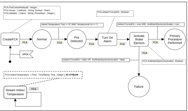
Figure 6.21 State Transitions of FireControlArtifact ... 147
Figure 6.22 State Transitions of FireStationAlertArtifact ... 147
Figure 6.23 Fire Control Conceptual Artifact Model ... 152
Figure 6.24 Fire Control Local CAMs Correspondences ... 153
Definition 3.1 Artifact System ... 41
Definition 3.2 Artifact Class ... 42
Definition 3.3 Service ... 44
Definition 3.4 Service Precondition ... 44
Definition 3.5 Service Effect ... 45
Definition 3.6 Artifact Rule. ... 46
Definition 4.1 Conceptual Artifact Model ... 89
Definition 4.2 Repository. ... 89
Definition 4.3 Task ... 89
Definition 4.4 Flow Connector ... 90
Definition 5.1 Artifact Integration System. ... 102
Definition 5.2 Correspondence Function: ... 106
Definition 5.3 Data Attributes Correspondence Function ... 110
Definition 5.4 Integration Function ... 111
Definition 5.5 Condition Integration Function ... 111
Definition 5.6 Artifact Mapping Function: ... 120
Definition 5.7 Repository Mapping Function ... 120
Definition 5.8 Task Mapping Function ... 121
Definition 5.9 Data Attribute Mapping Function ... 122
List of Examples
Example 3.1 Artifact System ... 41
Example 3.2 Artifact Class ... 43
Example 3.3 Ad hoc Service 1 ... 45
Example 3.4 Ad hoc Service 2 ... 45
Example 3.5 Stream Service ... 46
Example 3.6 Artifact Rule 1 ... 47
Example 3.7 Artifact Rule 2 ... 47
Example 3.8 Artifact Rule 3 ... 47
Example 3.9 Create Artifact Statement ... 51
Example 3.10 Create Service Statement 1 ... 52
Example 3.11 Create Service Statement 2 ... 52
Example 3.12 Create Service Statement 3 ... 53
Example 3.13 Create Rule Statement 1 ... 54
Example 3.14 Create Rule Statement 2 ... 54
Example 3.15 Create Rule Statement 3 ... 55
Example 3.16 Create Rule Statement 4 ... 55
Example 3.17 New Statement ... 56
Example 3.18 Retrieve Statement 1 ... 58
Example 3.19 Retrieve Statement 2 ... 58
Example 3.20 Update Statement ... 59
Example 3.21 Insert Into Statement ... 60
Example 3.22 Remove From. ... 60
Example 3.23 Delete Statement. ... 60
Example 4.1 Repository. ... 90
Example 4.2 Task ... 90
Example 4.3 Flow Connector ... 91
Example 4.4 Conceptual Artifact Model ... 91
Example 4.5 Generating Artifact Classes ... 93
Example 4.6 Generating Services... 95
Example 4.7 Generating Artifact Rules ... 97
Example 5.1 Integration Function ... 111
Example 5.2 Condition Integration Function ... 111
Example 5.3 Merging Sub-Phase ... 117
Example 5.4 Artifact Mapping Function. ... 120
Example 5.5 Repository Mapping Function ... 121
1
Introduction
Context
Artifact-centric process modeling is a Business Process Modeling approach that seeks to explicitly unify data and process, and consequently eliminates the dichotomy that has separated the Database and the Business Process Management communities.
Artifact-centric processes were first introduced by IBM research labs in 2003 [NiCa03]. The artifact-centric approach, rather than Relation Schema modeling in Databases [AbHV95], or Workflow modeling in Business Process Management [DTKB03], combines both data and process into self-contained entities, known as Artifacts that serve as the basic building blocks from which models of (business) processes are constructed.
In general, an artifact-centric process referred to as an Artifact System [BGHL07] is formed from three main components:
1) Artifact Classes including Information Models for data related to the artifacts and state-based Lifecycles describing possible stages,
2) Services the basic units of work that operate on Artifacts, and
3) (Business) Rules describing the possible ways that Services can be invoked on Artifacts by following transitions between states of their Lifecycles.
An Artifact System is thus a blend of data and process about dynamic entities that capture their end-to-end journeys and evolve according to specified lifecycles in order to achieve particular goals.
Figure 1.1 illustrates an example of an Artifact System about an Order artifact. The Information Model of the Order Artifact class has data attributes for registering information about the order id, product, quantity, client, shipment address, whether the product is available in stock, date retrieved, and delivery date. The Lifecycle includes states for representing the different stages of an Order Artifact including; Created, NotAvailable, Available, Retrieved, and Delivered. The list of Services acting on Order Artifact includes:
1) Create Order: creates a new Order Artifact instance and registers necessary information.
2) Check Availability: checks if the requested product and quantity are available in stock.
1.1 CONTEXT 3
3) Retrieve Product: retrieves the product from the stock. And, 4) Deliver Product: delivers the product to the shipment address.
Rules are declarative ECA (Event-Condition-Action) rules that are represented as arrows in Figure 1.1. They are responsible for invoking Services and changing the state of Artifact instances.
Figure 1.1 Artifact System example
By leveraging process models into a semantic level, artifact-centric processes provide an intuitive and flexible framework for executing and managing data-driven processes. As reported in [CoHu09, Hull08], the artifact-centric approach has successfully been applied to process management and case handling, and has demonstrated many advantages such as enabling a natural modularity and componentization of processes, supporting process transformations and changes, providing a framework of varying levels of abstraction, and understanding the interplay between data and process in ways not supported by previous Computer Science abstractions. As a result, end-users can manage, control, and transform artifact-centric processes from day to day with minimal to no intervention from IT specialists and experts.
Over the last few years, artifact-centric processes have proliferated at a phenomenal pace with the wide range of promising applications including finance, monitoring, and virtual organization. Yet another promising application of artifacts is the Internet of Things (IoT) in which smart objects link networks of sensors and actuators. In this context, smart objects can be modeled as self-evolving artifacts gathering data streams from various sensors, detecting complex events, and performing actions on actuators. The Internet of Things, where numerous connected devices are integrated with
Created NotAvailabe Retrieved Delivered Lifecycle - OrderId : Integer - Product : String - Quantity : Integer - ClientName : String - ShippmentAddress : String - InStock : Boolean - DateRetrieved : Date - DeliveryDate : Date Order Artifact Availabe Artifact Class Information Model Services Rules Rules Create Order Check Availability Retrieve Product Deliver Product
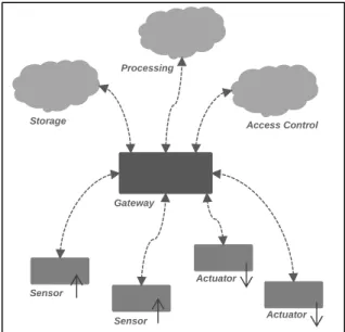
Internet-based protocols in order to build high-level business services, can be architecturally divided into three layers as illustrated in Figure 1.2:
1) Devices layer: This is the lowest-level layer, which consists of a set of sensors and actuators interacting with their physical environment. 2) Gateway layer: This is the intermediate layer, which is able to provide
a unified access point to the variety of connected objects.
3) Business services layer: The Internet of Things presents considerable business opportunities, not only from a device manufacturing perspective, but also from a business perspective through business services and high-level applications.
Figure 1.2 Internet of Things architecture
The artifact-centric approach can provide an abstraction over the three layer architecture of Internet of Things and its various components. Through the use of Artifact Classes, Services, and Rules, an Artifact System can represent all the low-level components of Internet of Things including sensors, actuators, storage, processing, access control, and gateways.
As a result, the artifact-centric approach demonstrates many advantages and benefits including; a natural modularity and componentization of self-contained entities and a framework of varying levels of abstraction in order to develop goal-oriented components instead of function-oriented components in the case of Web Services.
Sensor Sensor Actuator Actuator Gateway Storage Processing Access Control
1.2 PROBLEM DESCRIPTION 5
Problem Description
Many of today’s businesses are formed by mergers and acquisitions with other businesses and as a result, business people have to deal with a number of heterogeneous Business Processes and Databases performing similar or different functionalities (i.e. manufacturing processes, sale processes) [PaSp00]. The same situation is applicable to the Internet of Things in which a large number of connected devices require to merge their data or provide a Unified View in order to be easily managed in a simple way rather than dealing with a large number of rows in distributed Database tables.
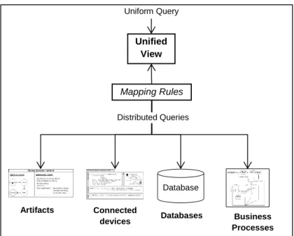
As described in [Lenz02], a convenient approach to manage heterogeneous processes and Databases consists of using a Unified View that centralizes the access to information and tasks available in these processes. A Unified View is a virtual process or data model that can be uniformly used to supervise, execute, and interrogate heterogeneous distributed processes and data entities without dealing with their differences and complexities. As a result, a uniform query based on a Unified View is transformed using mapping rules into the corresponding heterogeneous queries of the distributed data entities (i.e., Databases) or processes. Result sets of the heterogeneous queries are then transformed and merged using the mapping rules into a uniform result set compatible with the Unified View. The benefits of using Unified Views are managing huge number of entities at a large scale, facilitating evaluation and analysis of their data and behavior, and providing a centralized access point for administrators and casual users. Figure 1.3 illustrates the integration mechanisms.
Since artifact-centric processes have emerged as a new modeling paradigm and provided interesting applications in the context of Internet of Things to model artifact-based connected devices, this thesis’ work focuses on the problem of integrating heterogeneous artifact-centric processes. Integrating artifact-centric processes raises an acute problem because of the complexity of matching and mapping two or more artifacts at the level of their components (i.e. Information Models, Lifecycles, Services, and Rules). And as a result, traditional data integration and process merging solutions and techniques like [ChTr12, KuYY14, PaSp00] fail to address the complexity of artifact-centric process integration.
Figure 1.3. Integration mechanism
Moreover, given an artifact-based connected device, different variants can exist to handle different usages in different application domains. Variations may occur in the Information Model (semi-structured data), States (i.e. new intermediary states), Services (i.e. new services or same services with different signatures ...), and Rules (specifically tailored to an application domain).
Variants of artifacts consequently lead to heterogeneous artifact-centric processes. As a result, the integration of artifact-centric processes from different sources becomes a major challenge when we need to provide Unified Views for managing, querying and executing very large number of artifacts distributed across the Internet of Things.
Since artifact-centric processes combine three main components; Artifact Classes, Services and Rules, the integration problem of two or more artifacts requires simultaneously the integration of their Information Models, Lifecycles, Services and Rules. However, integration problems have been extensively investigated in disciplines such as Data Integration, Databases, Business Process Merging but the complexity and richness of artifact structures requires specialized integration semantics and approaches.
The challenges facing artifact-centric process integration can be classified into four different levels:
1) Integration Semantics Level: Artifact Systems combine both process and data aspects into three components; Artifact Classes including Information Models and Lifecycles, Services, and Rules. As a result, specialized
Unified View Mapping Rules Connected devices Uniform Query Database Artifacts Databases Business Processes Distributed Queries
1.3 CONTRIBUTIONS 7
integration semantics that address these three components should be defined. Moreover, these integration semantics should support different kinds of semantic relationships (i.e. unique, equivalent, and composition) between elements of the different Artifact Systems’ components.
2) Conceptual Artifact Model Level: In order to define effective integration semantics, Artifact Systems should be represented using conceptual models that capture their three components. These conceptual models should not only be simple, intuitive and holistic but can also be used to generate working Artifact Systems.
3) Artifact-specific Language Level: In order to effectively create, execute, manipulate, and interrogate Artifact Systems, artifact-specific languages should exist to specifically target artifacts and take full advantage of their semantic nature. Additionally, Artifact-specific languages should be used in order to interrogate generated Unified Views, and,
4) Extended Artifact Level: Since artifacts are mainly applied to traditional business processes, artifacts require to be extended with data stream capabilities in order to support modern IoT-based processes.
Contributions
In this thesis, we focus on the problem of artifact-centric process integration in the context of the Internet of Things through the representation of Artifact Systems, using conceptual models and merging of conceptual models according to correspondence relationships between different artifact component elements.
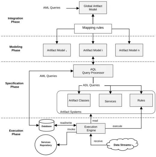
To this end, we propose a global artifact-centric process integration framework as illustrated in Figure 1.4. The integration framework is based on four main phases: Modeling, Specification, Integration, and Execution.
In the Modeling Phase, we model Artifact Systems using conceptual models that we refer to as Conceptual Artifact Models (CAMs). We propose the Conceptual Artifact Modeling Notations (CAMN) as minimalistic graphical notations that we use in order to model CAMs. CAMs are not only characterized by containing all required information for generating Artifact Systems, but they also form the basis of the integration and generation of Unified Views of heterogeneous artifacts.
Figure 1.4. Artifact-centric process integration framework
In the Specification Phase, we generate Artifact Systems from CAMs that are modeled in the modeling phase. We also propose the Artifact Query language (AQL), an artifact-specific language, that we use in order to express and implement Artifact Systems. The AQL is a high-level declarative language similar to the SQL and specifically targets artifacts taking full advantage of their semantic and data structutres. The AQL is made of two parts: the Artifact Definition Language (ADL), and the Artifact Manipulation Language (AML). The ADL contains statements to define Artifact Classes, Services, and Rules. The AML contains statements to instantiate, manipulate, and interrogate artifact instances. Moreover, the AQL supports Data Streams and Continuous Query capabilities and allows Complex Event Processing (CEP) over data streams through the use of Artifact Rules.
In the Integration Phase, we integrate several local CAMs in order to generate one global CAM that is used as a Unified View of heterogeneous artifacts. We propose semantic-based integration based on:
Artifact Classes Services Rules
Modeling Phase Specification Phase Artifact Model 1 Execution Phase Execution Engine execute Artifact Systems Database Services Repository read/write invoke read
Artifact Model i Artifact Model n Global Artifact Model Integration Phase Mapping rules ADL Queries AQL Query Processor AML Queries AML Queries Data Streams receive
1.4 DOCUMENT ORGANIZATION 9
a) The identification of three types of correspondence relationships (unique, equivalent, and composition) between different elements of CAMs,
b) The generation of a global CAM by merging local CAMs based on the identified correspondences, and
c) The specification of mapping rules in order to translate AML queries and data between the global and local CAMs with regards to the type of CAM elements.
Finally, in the Execution Phase, we execute Artifact Systems using an execution engine based on translating AQL queries into semantic queries. Semantic queries are then executed on a Database Management System in order to perform relational and stream operations. The execution engine is also responsible for invoking Services.
We validate our artifact-centric process integration framework by developing a prototype, consisting of several modules and graphical user interfaces.
Document Organization
The remainder of the document is organized as follow. Chapter two is a survey of related works. Chapter three defines the Artifact System and presents the Artifact Query Language (AQL). Chapter four presents the Conceptual Artifact Modeling Notations (CAMN) and defines Conceptual Artifact Models (CAMs). It also describes the semantics of generating Artifact Systems from CAMs. Chapter five defines integration semantics of CAMs. Chapter six describes the prototype implementation. Finally, chapter seven concludes our contributions with new research perspectives and open research issues.
2
Related Works
In this thesis, we treat problems related to Business Process Modeling. In particular, we focus on modeling, execution, and integration of artifact-centric Business Processes and their applications to modern smart processes and services.
In this chapter, we present the state of the art of existing works and compare them with regard to our research problem. The reviewed research fields and domains include: Business Process Modeling, Data Integration, Business Process Merging, and Query Languages.
In Section 2.1, we start with a brief introduction of Business Process Models that puts into perspective activity-centric and artifact-centric approaches.
In Section 2.2, we make an overview of activity-centric Business Process Modeling. Moreover, we illustrate advantages and disadvantages of the activity-centric approach in contrast to the artifact-centric approach.
In Section 2.3, we present artifact-centric Business Process Modeling. We describe the artifact-centric approach and its existing formal models. We also make a comparison between existing formal models and the proposed formal model illustrating the advantages of our proposition.
In Section 2.4, we describe existing artifact modeling notations and framework and illustrate their advantages and disadvantages. We then make a comparison between existing artifact modeling notations and frameworks and the proposed artifact modeling notations and framework.
In Section 2.5, we investigate data integration and show the need for an alternative approach to integrate artifact-centric processes.
In Section 2.6, we describe Business Process Merging and Views approaches. Similarly to Data Integration, we demonstrate the need for an alternative approach to integrate artifact-centric processes.
In Section 2.7, we describe existing Query Languages including one-time and continuous query languages. We also compare existing query languages to the proposed query language while illustrating its advantages.
Business Process Models
Business Process is the way an organization conducts its business in order to achieve its business goals. As stated in [Ritt04], a Business Process is one of the first things to consider when organizations need to improve their effectiveness and efficiency. Not having a well-defined and standardized
2.1 BUSINESS PROCESS MODELS
13
Business Process, may lead an organization to unfavorable consequences since the choice of how to conduct the business is left for each employee to make.
The Business Process Model (BPM) is an abstract representation of the Business Process of an organization. This abstract representation is most often a graphical representation that consists of a set of interconnected modeling primitives. As described in [LiBW07], a Business Process Model allows the analysis of the Business Process and the reasoning about how to conduct it in the most efficient and effective manner.
Two major approaches to modeling Business Processes exist:
The Activity-centric approach in which Business Processes are modeled as sequences of Tasks or Activities [DuTe01]. And,
The Artifact-centric approach in which Business Processes are modeled based on semantic entities referred to as Business Artifacts [NiCa03].
[EsWi03, TrAS08, VTKB03] describe three major aspects that are involved in any Business Process Model:
The process aspect (Control-Flow) describes Tasks or Activities, and their logical order of execution.
The data aspect (Data-Flow) describes the evolution of data in the Business Process.
The resource aspect concerns the organizational structure and describes roles that are responsible for executing tasks.
In the activity-centric Business Process Modeling, the process aspect is fundamental and vital to the Business Process Model and represents its core [VTKB03]. On the other hand, data and resource aspects are secondary and are layered on top of the process aspect and provide it with necessary support. In this approach, models describes actions that need to be performed by business actors (human or system) using resources of an organization and their logical order of execution in order to achieve business goals [LiBW07]. On the other hand, in artifact-centric Business Process Modeling both process and data aspects are involved from the beginning in the Business Process Model. The main building blocks of this approach are Business Artifacts [NiCa03], combining both process and data aspects of a Business Process. In this approach, Business Process Models are built from Lifecycles of Business Artifacts.
As described in [CoHu09], activity-centric Business Process Models have been found to have many disadvantages especially when applied in situations that require dynamic modelling and transformations like in knowledge-driven Business Processes. In this kind of situations where the Control-Flow is not known before executing the process, an artifact-centric approach is more flexible and suitable than an activity-centric approach.
Activity-Centric Business Process Modeling
In activity-centric Business Process Modeling, the core components of the process model comprise Activities, and Control-Flows. Activities are the units of work that represent single logical steps within a Business Process. An Activity may be performed by a human actor or an automated system. Control-Flows are used to connect Activities together to form logical steps of a Business Process.
Activity-centric Business Process Models can be supported by a Workflow Management System (WFMS) in order to automate suitable parts of the Business Process as described in [Ritt04]. In this case, the Business Process Model is referred to as a Workflow model. An overview of Workflow Management is described in [GeHS95] where a Workflow model can be read, executed, and controlled by a Workflow Management System (WFMS).
Different modeling languages and notations related to Business Process and Workflow modeling exist. For examples, UML Activity Diagrams [DuTe01], Business Process Model and Notation (BPMN) [Fort09], and Yet Another Workflow Language (YAWL) [VaTe05] are the most common and used modeling languages and notations. Moreover, these modeling languages and notations are interchangeably used by business analysts and IT specialists.
From an analysis perspective, [VTKB03] performs a study on Workflow patterns. In this study, twenty six Workflow patterns are identified and described. Moreover, [VTKB03] concludes that current Workflow Management Systems (WFMS) can only support a subset of the twenty six workflow patterns. related work such as [MSMP05, VaVa04] describe four major Workflow patterns that are involved in any Workflow including Sequence, Parallel Path, Alternative Path, and Iteration where:
Sequence pattern represents several Activities that should be executed in order, one after the other.
2.2 ACTIVITY-CENTRIC BUSINESS PROCESS MODELING
15
Parallel Path pattern represents several Activities that can be executed at the same time or in no particular order.
Alternative Path pattern path represents the decision of executing one or more Activities from several Activities.
Iteration pattern is when several Activities must be repeatedly executed until a condition is met.
From the Unified Markup Language (UML) perspective, [DuTe01, Ritt04] describe the use of UML Activity Diagrams in modeling Workflows. The UML Activity Diagram [StHa04] provides basic constructs that can be combined in order to model the major patterns of Workflows. Figure 2.1 illustrates the UML Activity Diagram constructs that includes: Start, End, Fork/Join, Decision/Merge, Activity and Activity Edge. [StHa04, StHa05] define formal semantics for UML Activity Diagrams. While [EsWi03] makes a comparison between Petri Nets and UML Activity Diagrams. On the other hand, [MSMP05] presents an approach to the modeling and analyzing of Business Processes based on UML Activity Diagrams and Petri Nets where;
Sequence patterns are modeled using Activities and Activity Edges. Parallel Path patterns are modeled using Fork/Join constructs.
Alternative Path patterns are modeled using Decision/Merge constructs.
Iteration patterns are modeled using a combination of Decision/Merge and Activity Edges constructs. Finally,
Start and End constructs are respectively used to denote the start and end of the Business Process.
Figure 2.1 UML Activity Diagram modeling constructs
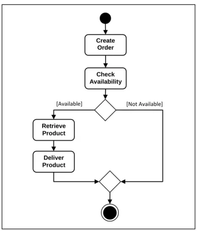
Figure 2.2 illustrates an example of a Workflow model about an order process modeled as UML Activity Diagram. After creating an order, it is checked for availability. If it is available, the product is retrieved and delivered. Otherwise, the process terminates.
Activity name
Activity Fork/Join Decision/ Merge
Figure 2.2 UML Activity Diagram example
From a different perspective, [Fort09] describes the Business Process Modeling Notation (BPMN). While [VaTe05] describes the Yet Another Workflow Language (YAWL). Works such as [Whit04] and [FoFo09] illustrate and compare how to model Workflow patterns described in [VTKB03] using UML Activity Diagrams, BPMN, or YAWL. They conclude that the three modeling notations can be adequately used to model most Workflow patterns. Similarities between the three modeling notations exist and are due to the fact that they are designed to solve the same basic problem; the diagramming of procedural business processes. Moreover, differences between the three modeling notations also exist and are due to the target users and goals of the modeling notations; BPMN was created as a graphical notation for business people to use. UML was created in order to standardize modeling for software development. YAWL was created in order to provide comprehensive support for Workflow patterns and to design executable Workflow models.
In summary, activity-centric Business Process Modeling focuses on modeling Business Processes based on Activities. An activity-centric Business Process Model tends to be easier to be developed than an artifact-centric Business Process Model since key Activities in a Business Process
Create Order Check Availability Retrieve Product Deliver Product
2.3 ARTIFACT-CENTRIC BUSINESS PROCESS MODELING
17
can be easily identified. Moreover, business logics are defined explicitly using Control-Flows which result in an explicit process model which contributes towards Business Process awareness in the organization. However, data are incorporated at a limited level as inputs and outputs of Activities which limits the understanding of possible effects of processing steps on key business entities [NgOt13]. Moreover, the explicit definition of Control-Flows is not suitable in situations that require dynamic modelling and transformations like in knowledge-driven Business Processes that are characterized by not having predefined Control-Flows. Instead, skilled and knowledgeable workers decide the best course of action according to each case like in the healthcare domain. In this kind of processes, an artifact-centric approach is more flexible and suitable than the activity-artifact-centric approach as described in [MaHV12, Whit09].
Artifact-Centric Business Process Modeling
In artifact-centric Business Process Models, the data aspect of Business Processes is involved from the beginning as opposed to the activity-centric approach that leaves it to later stages as input and output of tasks.
In this approach, data and process aspects are combined into semantic entities referred to as Business Artifacts [NiCa03]. A Business Artifact is composed from an Information Model and a Lifecycle. The Information Model is a set of attribute/value pairs representing business related data and objects. The Lifecycle describes the possible stages that a Business Artifact can pass through during the Business Process. Business Artifacts are used by business people in order to record and track progress toward completing business goals.
The concept of using Business Artifacts as building blocks for Business Processes Models was first introduced in [NiCa03] and was further described in [BhHS09, CoHu09, Hull08]. In this approach, Lifecycles of Business Artifacts are represented using finite state machines. Lifecycle of a Business Artifact can interact with the Lifecycles of other Business Artifacts in the Business Process. A Business Process Model is formed from all Lifecycles of Business Artifacts involved in the Business Process.
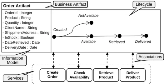
In [Hull08], a framework for analyzing and working with artifact-centric Business Process Models is presented. The framework, referred to as the BALSA framework, describes four dimensions that are involved in any artifact-centric Business Process Model, including: Business Artifact
(Information Model), Lifecycle, Services, and Associations. Figure 2.3 illustrates an example of the BALSA framework representation of an Order artifact.
Figure 2.3 BALSA Framework example
By varying the implementations of the four dimensions of the BALSA framework, different kinds of artifact-centric Business Process Models ranging from procedural to declarative can be constructed. A procedural model describes “how” processing should be done in a step-by-step manner using a finite-state machine. While a declarative model describes “what” should be done using statements in a particular language.
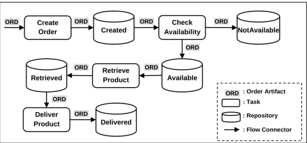
In [GeBS07, GeSu07], a formal model for procedural artifact-centric Business Process Models is defined. In this formal model, Associations and Lifecycles are represented using finite-state machines composed from Tasks, Repositories, and Flow Connectors where:
Tasks represent units of work that operate and update Information Models of Business Artifacts.
Repositories represent storage locations for Business Artifacts awaiting future processing if any. And,
Flow Connectors transport Business Artifacts between Tasks and Repositories.
Figure 2.3 illustrates the Lifecycle of the Order artifact represented as a finite-state machine composed from Tasks, Repositories, and Flow Connectors. Moreover, the problem of verification of procedural artifact-centric Business Process Models is studied in [GeSu07] where a language for specifying and verifying artifact lifecycle behaviors is presented.
Created NotAvailabe Retrieved Delivered Lifecycle - OrderId : Integer - Product : String - Quantity : Integer - ClientName : String - ShippmentAddress : String - InStock : Boolean - DateRetrieved : Date - DeliveryDate : Date Order Artifact Availabe Business Artifact Information Model Services Associations Create Order Check Availability Retrieve Product Deliver Product
2.3 ARTIFACT-CENTRIC BUSINESS PROCESS MODELING
19
Transformation between activity-centric and artifact-centric Business Process Models is performed in [KuLW08, MeWe13].
Figure 2.4 Lifecycle of Order artifact as Tasks, Repositories and Flow Connector
On the other hand, [BGHL07] defines a formal model for declarative artifact-centric Business Process Models. In this formal model, Associations are represented as declarative Business Rules. Services are also declaratively represented as Semantic Web Services specifications. Business Rules, as variants of Event-Condition-Action (ECA) Rules describe conditions under which actions should be performed. Conditions involve Information Models and Lifecycles’ states. Actions invoke Services, or change Lifecycles’ states. The problem of verification of correctness properties for declarative artifact-centric Business Process Models is studied in [DHPV09, HCDD11].
A formal model for artifact-centric Business Process Models based on declarative Guard-Stage-Milestones (GSM) Lifecycles was introduced and defined [DaHV13, HDDF11a, HDDF11b]. In this formal model, Lifecycles are represented using Guards, Stages, and Milestones. Milestones correspond to business objectives that a Business Artifact might achieve. Stages correspond to collections of Tasks that are intended to achieve Milestones. And, Guards control when Stages can be opened for execution. The GSM provides a declarative model that supports parallelism and hierarchies in Business Artifact’s lifecycles. The problem of verification of GSM models based on symbolic model checking was studied in [GoGL12]. In [PoDu12, PoFD15], Petri Net Lifecycles generated from event logs are transformed into GSM models.
In summary, three different formal models for artifact-centric Business Process Models exist. The first formal model is based on procedural finite state machines. The second formal model is based on declarative Business Rules. And, the third formal model is based on declarative GSM Lifecycles.
Created ORD Create Order Check Availability Retrieve Product Deliver Product ORD NotAvailable Available ORD ORD ORD Retrieved ORD ORD Delivered ORD : Order Artifact : Task ORD : Repository : Flow Connector ORD
Moreover, a declarative model is better suited than a procedural model in the context of Business Process transformation and customization. In this case, adding declarative rules or editing existing declarative rules is simpler than editing, recompiling, and deploying of a finite-state machine. As a result, the formal model we propose in this thesis is based on declarative Business Rules we refer to as Artifact Rules.
On the other hand, existing artifact formal models lack the support for data streams generated by sensors, and actuators. As a result, existing artifact formal models are not suitable for modeling of modern day smart processes and thus smart services that require the integration of data streams, sensors, and actuators into same processes.
In comparison, the proposed artifact formal model offers support for data streams in the form of Stream Attributes included in artifacts’ Information Models. Additionally, the proposed artifact formal model defines two types of Services that can operate on artifacts;
Ad-hoc Services that perform one time actions on actuators. And, Stream Services that continuously read data from stream sources like
sensors.
Moreover, existing artifact formal models define Information Models as sets of simple attribute/value pairs or as sets of database relations (i.e., tuples). When using relational databases to model and manage artifacts, manipulating artifacts must be performed by manipulating different database relations using SQL queries. This approach of dealing with low-level database relations or attributes does not take full advantage of the semantic nature of artifacts and the different relationships that can exist between them. In comparison, in our proposed artifact formal model, which defines Information Models as data structures, introduce four types of data attributes; Simple, Complex, Reference, and Stream. As a result, these types of data attributes allow the manipulation of artifacts at a high-level and hide the low-level database relations and SQL queries.
Similarly, the proposed artifact formal model represents artifact relationships using high-level Reference data attributes that hide the low-level database relations. Table 2.1 summarizes the differences between existing and proposed artifact formal models.
2.4 ARTIFACT MODELING NOTATIONS AND FRAMEWORKS
21
Table 2.1 Comparison between existing and proposed artifact formal models
Existing Formal Models Proposed Formal Model Data Streams do not support data streams
support data streams using Stream Attributes Sensors do not support sensors using Stream Services support sensors Actuators do not support actuators using Ad-hoc Service support actuators
Manipulation
low-level dealing with attribute/value pairs and
database relations
high-level dealing with simple, complex,
reference, and stream data attributes Artifact Relationships Representation low-level using database relations high-level using reference attributes
Artifact Modeling Notations and Frameworks
From modeling notations and frameworks perspective, many works have focused on defining formal and graphical notations to model and execute artifact-centric Business Processes. We analyze and distinguish between these notations according to three criteria:
1. Conceptual vs Executable Notations: The first criterion distinguishes between whether notations are used to construct Conceptual Models or Execution Models. A Conceptual Model is a graphical model that is designed by a business person and is used to represent a Business Process at a conceptual level. On the other hand, an Execution Model is an IT related technical and textual model that is defined by an IT specialist or a computer system and is used to execute a Business Process. An Execution Model can also be automatically generated from a Conceptual Model.
2. Procedural vs Declarative Notations: The second criterion distinguishes between procedural or declarative notations. Procedural notations are used to construct finite-state based artifact models whereas declarative notations are used to construct rule-based artifact models.
3. Graphical vs Textual Notations: The third criterion distinguishes between graphical or textual notations. Graphical notations are used to
model declarative or procedural Conceptual Models. Textual notations are used to model declarative or procedural Execution Models.
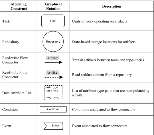
With the exception of the GSM notation [DaHV13], existing graphical modeling notations are based on the modeling constructs and patterns described in [LiBW07, NiCa03]. [NiCa03] describes three modeling constructs; Task, Repository, and Flow Connector that can be used to model artifact lifecycles. While [LiBW07] describes nine modeling patterns including; Pipeline, Repository, Branch, Convergence, Project, Creation, Synchronization, Rework, and Disposal that can be employed in Business Artifact modeling.
Cohn et al. [CDHP08] introduce Siena to graphically model Business Artifact Lifecycles as procedural finite-state machines based on Tasks, Repositories, and Flow Connectors. Siena provides the capability to generate XML-based Business Artifacts that are then deployed and executed in the Siena Runtime Container. The procedural specification of finite-state machines in Siena makes it unsuitable for Business Process transformation and customization where a declarative approach is more favorable.
In [LoNy11], Business Process Modeling Notation (BPMN) extensions have been introduced to model artifact-centric Business Process Models. These BPMN extensions include; Artifacts, Object Lifecycles, Location Information, Access Control, Goal States, and Policies. Artifacts represent the process model’s basic building blocks. Object Lifecycles specify artifacts’ states. Location Information specifies how artifacts change their location. Access Control specifies the remote accessibility of artifacts. Goal States specify desired final states. And, Policies are used to remove undesired behavior. BPMN extensions provide graphical notations and environment for modeling procedural artifact-centric processes but do not support a declarative modeling approach.
In [LLQS10], Artifact Conceptual Flow or ArtiFlow (re-named EZ-Flow in [XSYY11]) is introduced. The ArtiEZ-Flow model relies on four types of constructs: Business Artifacts, Services, Repositories, and Events. ArtiFlow models are executed by translating them into BEPL-based Workflows. In order to make the translation into the BPEL feasible, ArtiFlow manages execution control through the use of Events. A modeling tool for Artiflow models is designed and developed in [ZYLL11]. Figure 2.5 illustrates an Artiflow example. Similarly to BPMN extensions, ArtiFlow provides graphical notations and environment for modeling procedural artifact-centric processes but do not support a declarative modeling approach.
2.4 ARTIFACT MODELING NOTATIONS AND FRAMEWORKS
23
Moreover, the use of a generated event when a Task is executed in order to invoke the next Task makes Artiflow more process oriented.
Figure 2.5 Artiflow example
The ArtiNets model, a variant of artifact-centric process models is introduced in [KuSu10]. It supports the specification of constraints on artifact lifecycles. Similarly to the Declarative Service Flow Language (DecSerFlow) [VaPe06], ArtiNets also allow declarative style in specifying constraints on artifact lifecycles. The key components of ArtiNets model are: Artifacts, Services, Places, and Transitions. ArtiNets model is closely related to Petri Nets [Mura89], but only they differ in two aspects: Artifacts in ArtiNets replaces Tokens in Petri Nets, and ArtiNets have different transition firing rule than Petri Nets.
[EQST12] models artifact-centric business processes with the Unified Modeling Language (UML) [RuJB04]. In this work, Business Artifacts (Information Models) are represented as Class Diagrams. Lifecycles are represented as State Machine Diagrams. Services are declaratively specified as preconditions and post-conditions using the Object Constraint Language (OCL) [CaGo12]. Finally, Associations are procedurally specified using Activity Diagrams.
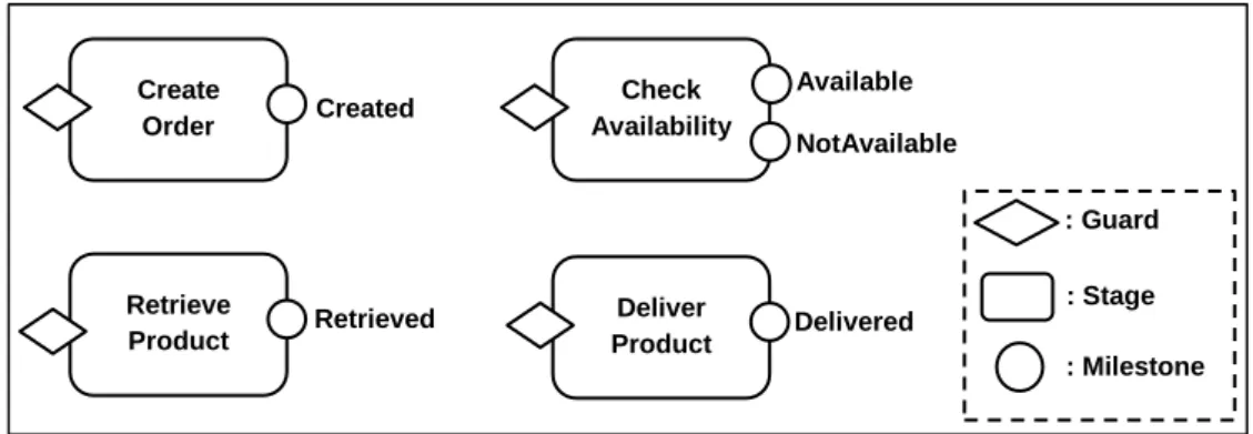
On the other hand, modeling notations for declarative Business Artifact models based on the GSM (Guard-Stage-Milestones) formal model are introduced in [DaHV13, HDDF11a, HDDF11b]. The GSM paradigm seeks to graphically model Business Artifact lifecycles using Guards, Stages, and Milestones. Declarative rules referred to as Sentries open or close Stages, and consequently validate or invalidate Milestones. By using Guards, Stages and Milestone as modeling primitives, the GSM notation allows parallelism and hierarchies in Business Artifact lifecycles. Moreover, GSM notation served as the foundation for the Case Management Modeling and Notation (CMMN)
Created ORD ORD Not Available Available ORD ORD : Order Artifact : Service ORD : Repository : Read (Pull) Create Order E2 E1 Check Availability E2 : Write (Push) E E : Consume Event : Produce Event
[MaHV12] core model. The Barcelona prototype provides design editor and runtime environment for Business Artifact models based on the GSM paradigm [HBGV13]. Figure 2.5 illustrates GSM representation of the Lifecycle of the Order artifact. The GSM approach not only supports a declarative specification of artifact-centric business processes but it also provides graphical modeling notations and environment which simplifies the modeling phase. However, GSM does not support data streams, sensors, and actuators and is developed to be used by Business People which makes it unsuitable for modeling modern day smart processes.
Figure 2.6 GSM representation of the Lifecycle of the Order Artifact
From the textual notations perspective, the Business Entities and Business Entity Definition Language (BEDL) are introduced in [NKMH10, NPKM11]. The BEDL is an XML-based language that specifies artifact-centric Business Process Models based on; Business Entities (or Artifacts), Lifecycles, Access Policies, and Notifications. The BPEL4DATA is then used to consume Business Entities and execute processes. Even though BEDL is a textual language, BEDL does not support a declarative specification of centric business process models. Instead, the BEDL specifies artifact-centric business process models as technical XML-based finite state machines. As a result, the BEDL complicates the design and modeling phase of artifact-centric business process models.
Abiteboul et al. [ABGM09] formalize business artifact processes using the Active XML (AXML) approach where a Business Artifact instance is written as an XML document with embedded function calls. The Business Artifact process is thus executed by invoking embedded functions when associated condition holds and assigning their results to Business Artifact attributes. The Active XML introduces a declarative specification of artifact-centric business process models which makes it suitable for Business Process transformation and customization. Nonetheless, the Active XML does not provide a graphical modeling notation that simplifies the modeling phase and contribute towards process awareness in the organization.
Create Order Check Availability Created Available NotAvailable Retrieve Product Retrieved Deliver Product Delivered : Guard : Stage : Milestone
2.4 ARTIFACT MODELING NOTATIONS AND FRAMEWORKS
25
In [YoLi10], the Artifact-Centric Process Model (ACP model) is introduced in order to support inter-organizational business process modeling. In [YoLZ11], an extended version of the ACP model is presented and is referred to as Artifact-Centric Collaboration Model (ACC model). The core modeling constructs of ACC model include: Role, Artifact, Task and Business Rule. Roles are organization roles participating in the collaboration. Moreover, ACC model distinguishes between two types of artifacts; local and shared artifacts. Local artifacts are the artifacts used internally within an organization. Shared artifacts serves as a contract between involved organizations, and it is used to indicate the agreed business stages towards the completion of the collaborative process. In [NgYL12], a framework for realizing artifact-centric process models in Service-Oriented Architecture (SOA) has been proposed and implemented based on the ACC model proposed in [YoLZ11]. One of the main advantages of ACC model is its support for declarative specification of Business Rules which are specified as constraints expressed with Event-Condition-Action Rules.
In comparison to existing works, we propose a graphical modeling notation referred as the Conceptual Artifact Modeling Notations (CAMN). The CAMN includes six modeling constructs; Task, Repository, Flow Connector, Data Attribute List, Condition, and Event. These six modeling constructs allows the design of procedural Conceptual Models that we refer to as Conceptual Artifact Models (CAM). The CAM is characterized by capturing both Information Models and Lifecycles of artifacts in the same Conceptual Model resulting in reduced design time and improves process awareness. Additionally, we describe eleven modeling patterns that cover the nine modeling patterns described in [LiBW07], in addition to modeling patterns that are required when data streams are involved. Moreover, the CAM includes required information for automatically generating declarative Execution Models that comply with our proposed formal model. A textual notation, referred to as Artifact Query Language (AQL), is also proposed in order to directly construct declarative Execution Models and interrogate them.
Table 2.2 and 2.3 summarize and compare different artifact modeling notations and frameworks covered in this section. Table 2.2 compares the Conceptual Models of the modeling approaches, if any, whereas Table 2.3 compares the Execution Models of the modeling approaches, if any. Similarly to [KuYY14], we perform our comparison based on the four dimensions of the BALSA framework; Information Model, Lifecycle, Services, and Associations. The ‘-’ symbol signifies that the BALSA