RESEARCH OUTPUTS / RÉSULTATS DE RECHERCHE
Author(s) - Auteur(s) :
Publication date - Date de publication :
Permanent link - Permalien :
Rights / License - Licence de droit d’auteur :
Bibliothèque Universitaire Moretus Plantin
Institutional Repository - Research Portal
Dépôt Institutionnel - Portail de la Recherche
researchportal.unamur.be
University of Namur
Light elements analysis using 3He microbeam
Terwagne, Guy; Bodart, Franz; Blanpain, Bart; Mohrbacher, H.; Celis, Jean-Pierre
Published in:
Nuclear instruments and methods in physics research B
Publication date:
1995
Document Version
Early version, also known as pre-print
Link to publication
Citation for pulished version (HARVARD):
Terwagne, G, Bodart, F, Blanpain, B, Mohrbacher, H & Celis, J-P 1995, 'Light elements analysis using 3He
microbeam', Nuclear instruments and methods in physics research B, vol. 104, pp. 266-270.
General rights
Copyright and moral rights for the publications made accessible in the public portal are retained by the authors and/or other copyright owners and it is a condition of accessing publications that users recognise and abide by the legal requirements associated with these rights. • Users may download and print one copy of any publication from the public portal for the purpose of private study or research. • You may not further distribute the material or use it for any profit-making activity or commercial gain
• You may freely distribute the URL identifying the publication in the public portal ?
Take down policy
If you believe that this document breaches copyright please contact us providing details, and we will remove access to the work immediately and investigate your claim.
s
. __
Nuclear instruments and Methods in Physics Research B 104 (1995) 266-270-_
F!!J ELSEWIECRNIiRilB
Beam Interactions with Materials & AtomsLight elements analysis using 3He microbeam
G. Terwagnea,*,
F. BodarV’, B. Blanpainb,
H. Mohrbacherb,
J.-P. Celisb
aLaboratoire d’Analyses par Rkactions Nuclhaires, rue Muzet 22, B-5000 Namur, Belgium bKatholieke Universiteit Leuven, Departement MTM, de Croylaan 2, B-3001 Heverlee, Belgium
Abstract
Coatings containing light elements such as carbon, nitrogen or oxygen play actually an important role in surface engineering as a means to improve the tribological performance. In this paper, we have studied the wear tracks on a diamond coating after a fretting test against a Cr steel ball. The microprobe facility of the LARN has been used to determine light elements concentration in the wear tracks because the size of the tracks was less than 100 pm and the transfer layer from the Cr steel counterbody was not uniform. Quarititative analysis of oxygen has been performed using the 2.392 MeV resonance of the 160(3He,c#50 reaction at 90”, while carbon has been measured simultaneously with the 12C(3He,p,)‘4N* reaction at 175”. The cross sections and the Q-value of this reaction are so high that an absorber is not required, so we can also measure the backscattered 3He particles in the same detector. A correlation between carbon, oxygen and iron has been made to investigate the possibility of interdiffusion between the diamond coating and the transferred material due to the fretting test.
1. Introduction
Light elements such as carbon, nitrogen and oxygen play a very important role in the surface treatment of steels, glasses or polymers Cl]. Protective, decorative or adhesive coatings can be made by different techniques like DC-magnetron sputtering, ion implantation, ion beam assisted deposition (IBAD) and chemical vapor deposition (CVD). Quantitative analysis and depth pro- filing of light elements can be performed using nuclear reaction analysis (NRA) induced by particles giving nu- clear reactions with a positive Q-value, while particle induced X-ray emission (PIXE) or Rutherford backscat- tering spectroscopy (RBS) are often not very convenient for light elements determination into substrate with 2 ~10. Deuterons and 3He incident particles are often chosen because they induce nuclear reactions with a high positive Q-value. Although the cross-sections for reac- tions like (d,p) or (d,a) on light elements are usually higher than the cross-sections for reactions induced by 3He particles at the same energy, reactions like (3He, p) or (3He,ol) produce one hundred times less neutrons than (d,p) or (d,u) reactions at the same energy. Reactions induced by 3He particles are also more sensitive to the near surface since the stopping power is higher for
*Corresponding author.
3He than for deuterons of the same energy. Microbeam analysis using 3He beam is not popular because most of the nuclear microprobes in the world are connected to tandem accelerators, which are limited in the bright- ness of the source. In the literature, we have seen only one paper on the microbeam analysis of deuterium using the d(3He,p)4He reaction at 980 keV [2] because this reaction has a high cross-section (70mb/sr). The cross-sections of reactions induced by 3He particles on light elements have been measured and reported by several authors [3-81 but a lack of data exists.
In this paper, we show that 3He particles can be used for simultaneous quantitative micro-analysis of light ele- ments such as carbon and oxygen. The cross-section of the nuclear reaction ‘60(3He,ao)150 shows a resonance at 2.392 MeV [9] which can be used for depth profiling even with a low current microbeam (0.5 nA). Carbon can also be analyzed in the same experimental conditions at backward angle using the ‘2C(3He,p,)14N reaction. As an example, we have treated the case of the performance of diamond coatings in unlubricated contacts subjected to low amplitude oscillatory sliding, also known as fret- ting wear [lo]. Other wear or friction tests using a pin on disk machine give also small tracks with dimensions in the range of 50-500 pm. Micro-analysis of tracks due to such tests are very useful in order to know the composi- tion of the transfer layer and the mechanism of wear involved.
0168-583X/95/%9.50 0 1995 Elsevier Science B.V. All rights reserved SSDI 0168-583X(95)00417-3
G. Terwagne et al. lNuc1. Instr. and Meth. in Phys. Res. B 104 (1995) 266-270 261
1
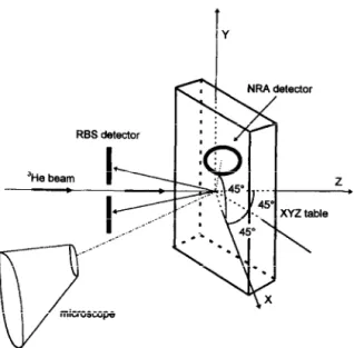
Y RBS detector z .Fig. 1. 3D view of the experimental setup. The RBS detector is in the horizontal plane formed by the incident beam and the normal of the specimen, while the NRA detector is placed at 45” from the same plane and at 90” relative to the incident beam. 2. Experimental details
2.1. Experimental setup
The 3He beam is produced with the 2.5 MV Van de Graaff accelerator located at LARN (Namur, Belgium).
The beam, typically 5 pm x 3 pm and 0.5 nA in intensity, is focused on the sample mounted on an XYZ table, which can be moved with stepping motors in the X and Y directions. The energy of the incident particles is 2.435 MeV, just above the energy of the 2.392 MeV res- onance of the ‘60(3He, Q)‘~O reaction and the incident angle between the impinging beam and the target is 45”. Two detectors are placed in the chamber as shown in Fig. 1. The first one, named a RBS detector, is a totally depleted annular surface barrier silicon detector located at 47 mm from the beam impact, showing a solid angle of 65 msr. The second detector is a passivated implanted planar silicon detector (PIPS), called a NRA detector, located at 90” relative to the incident beam direction and at 45” relative to the horizontal plane formed by the incident beam and the normal of the target. This detector is situated at 60 mm from the beam impact showing a solid angle of 37 msr. The bias voltage of the NRA detector was only 6 V in order to stop completely the 5.415 MeV alpha particles produced by the 160(3He,c10)‘50 reaction and to produce only a AE signal for the high energy protons produced by the 12C(3He,pJ14N reaction. The solid angles of both de- tectors have been calculated and measured by conven- tional RBS experiment on a known SnOz coating depo- sited on glass. An aluminum foil of 8 w thickness was placed in front of the NRA detector in order to stop the backscattered 3He particles, while no absorber was required for the RBS detector. The absolute charge deposited by the incident beam on the specimen can be
Fig. 2. Picture showing the track obtained on the diamond coating layer after the fretting wear test. The length of the index is 100 pm and the estimated dimension of the track is about 500 ‘pm.
G. Terwagne et al. /Nucl. Instr. and Meth. in Phys. Res. B 104 (1995) 266-270 268 1000 5 E : cl 500 cl. d 5 8 0 Energy (MeV) 1.0 1.5 2.0 2.5 3.0 3.5 4.0 4.5 100 200 300 Channel 400 500 3 . f 20- iii $ 15 - 0..
4 IO- .' ’ ‘2C(3He,pi)14N’ 160(3He,a,)150_
0 100 200 300 400 500
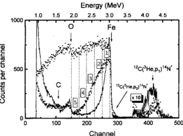
Fig. 3. RBS spectra recorded during the same incident charge (100 nCb) at three different impact points on the track showing three different thicknesses of the transferred layer. The full-line spectrum corresponds to a dark zone, the spectrum represented by crosses was taken in a semi-bright zone, while the dot spec- trum was recorded in a bright area of the specimen. The regions of interest labeled 1 to 5 cover the information coming from iron and are named Fe, to Fe, in Fig. 5.
integrated using a positive bias voltage (150 V) applied to the specimen in order to attract the secondary electrons.
2.2. Samples preparation
Diamond coatings of 5 pm thickness were grown on WC-Co flat inserts (grade KlO) with a hot filament chemical vapor deposition process [ll]. The reactor was operated under a hydrogen/methane mixture (50 mbar) with the assistance of a W filament at about 2100°C. The substrate temperature during deposition was approximately 900°C. The coatings were then submitted to a low amplitude oscillating sliding wear test. A full description of the testing device is given in ref. [12]. The lOOCr6 steel ball counterbody (10 mm diameter) was loaded with a dead weight of 4 N against the diamond coated flat. The diamond coated sample was oscillated with a stroke of 100 urn and a frequency of 10 Hz for 100000 cycles. Fig. 2 shows that a transferred layer has been formed [1] after the fretting test on the diamond coating in the contact zone.
3. Results and discussion
Fig. 3 shows three typical RBS spectra obtained at three different impacts with 2.435 MeV 3He particles. All spectra were recorded with the same incident charge (0.1 uCb). The full-line spectrum was recorded in a
Channel
Fig. 4. NRA spectrum recorded during an incident charge of 100 nCb and simultaneously with the dotted line spectrum from Fig. 3. The bias voltage of the NRA detector was chosen in order to stop completely the alpha particles from the 160(3He, CQ)‘~O reaction and to produce only a A.5 signal for the high energy protons produced by the “C (3He, pi)r4N* reactions.
dark area of the specimen, where only a thin layer of the counterbody has been transferred on the sample. The signals coming from iron and oxygen are clearly observed, while carbon and oxygen interfere. We can also observe that information coming from the ‘2C(3He, pi)14N nuclear reactions interfere with the RBS spectrum. The shape of the background under the RBS spectrum, due to nuclear reactions has been recorded outside the track and subtracted from the RBS spectra presented in order to obtain quantitative measurements. We have defined five different regions of interest covering the iron signal on the RBS spectrum. The first one, labeled 1, concerns the information coming from the surface, while the others represent the information coming deeper and deeper from the specimen. For example, there is no iron in the regions 4 and 5 for the full-line spectrum and in this case it is possible to obtain the concentration of oxygen directly from the RBS spec- trum when the transferred layer is thin. The spectrum represented by crosses was recorded in a semi-bright region, where the transferred layer of the counterbody is thicker. In that case, iron is present in layers 4 and 5. The last spectrum represented by dots was obtained on a bright area where the transferred layer of the counter- body is so thick that signals coming from iron and oxygen are mixed. In that case, oxygen cannot be esti- mated from the RBS spectrum and we need the informa- tion recorded in the NRA detector (Fig. 4). The tail observed for the iron peak of the RBS spectra can be explained in two different ways: the first one is the possi- bility for the diffusion of the transferred layer in the diamond coating and the second possible explanation is the roughness of the diamond coating, which is about 200 nm. We have simulated the full-line RBS spectrum
G. Terwagne et al. / Nucl. Instr. and Meth in Phys. Res. B 104 (1995) 266-270
+c’(~
0 5 10 15 20 25 0 5 10 15 20
position
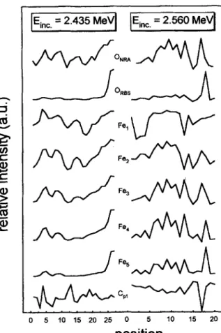
Fig. 5. Line-scans obtained at two different energies above the 2.392 MeV resonance of the ‘60(3He, CL,#~O reaction. One step
in the position scale represents 10 pm. The ONRA curves corres- pond to a region of interest on the *60(3He, c(~)‘~O peak (Fig. 4), while ORBS, Fei and Cpl curves were obtained from a region of interest which corresponds respectively to oxygen, iron and carbon from the 12C(3He,p,)‘4N reaction in the RBS spectrum (Fig. 3).
using the RUMP code [13], taking into account the roughness of the diamond coating, and we have found a 200 nm iron oxide layer containing carbon with the stoichiometry of Fe0.2300.46C0.31.
If should be noted that for all RBS spectra, carbon coming from the diamond coating can be measured using the ‘ZC(3He,p,)‘4N nuclear reaction and it is clearly seen that more carbon is observed when the transfer layer is thin. There is also an interference between the 12C(3He,p,)‘4N nuclear reaction and the 3He retrodif- fused by iron but in first approximation this contribution can be neglected. We can remove this contribution for absolute measurements.
Line-scans have been performed in the track shown in Fig. 2. To do this, we have introduced seven regions of interest on the RBS spectrum: the five regions in the iron signal as shown in Fig. 3, one region in the oxygen
269
information, labeled ORss and the last one on the peak corresponding to the 1zC(3He,p,)‘4N* reaction, named Cpl. Fig. 5 presents two line-scans of 27 and 20 steps; each step corresponds to a displacement of 10 pm. They were realized respectively at 2.435 and 2.560 MeV. For each point, the spectra (NRA and RBS) were recorded during 120 s and the total charge was also integrated during the same time for normaliz- ation of the data. The line-scans were normalized with the integrated charge and the results are presented in Fig. 5. The first energy was chosen just above the energy of the 2.392 MeV resonance of the 160(3He, c+,)~~O reaction and we can observe in Fig. 5 a correlation between the ONRA and Fe, or Fe, information, while no correlation can be found between ONRA and ORss or between ONRA and Fe,. At higher incident energy (2.560 MeV), a correlation between ONRA and Fe3 or Fe, is evident but no correlation can be observed between ONRA and Fe, or Fez. No correlation can be found between ONRA and ORss as mentioned above. This is due to the fact that the iron layer is so thick that the iron signal interferes with oxygen. We can conclude that iron and oxygen are bounded together and the stoichiometry can be measured by simulating the RBS spectrum obtained at one impact point as mentioned above. For both energies, we can observe an anticorrela- tion between ONRA and C,l, which proves that most of the information of the C,, peak is coming from the diamond coating.
4. Conclusions
Quantitative microbeam analysis of light elements like C and 0 is possible even with a 5 pm x 3 pm 3He beam of 0.5 nA intensity. It is more interesting to use a 3He beam in place of deuteron particles because the reactions in- duced by 3He particles are more surface sensitive and produce less neutrons. By combining RBS and NRA, it is also possible to find out the correlation between ele- ments. Carbon and oxygen can also be measured simul- taneously using two different detectors. Unfortunately, the literature concerning the cross-sections of the (3He, p) and (3He,a) is poor and therefore work remains to be done in this area.
Acknowledgements
This study was sponsored by the Belgian Program on Interuniversity Poles of Attraction, initiated by the Belgian State, Prime Minister’s Office-Science Policy Programming. Scientific responsibility is assumed by the authors. We would like to thank Yvon Morciaux for his technical assistance.
270 G. Terwagne et al. lNuc1. Instr. and Meth. in Phys. Rex B 104 (1995) 266-270
References
[l] H. Mohrbacher, B. Blanpain, J.P. Celis and J.R. Roos, Surf. Coat. Techn. 62 (1993) 583.
[2] C.J. Sofield, G.M. McCracken, L.B. Bridwell, J. Shea, E.S. Hotston and S.K. Erents, Nucl. Instr. and Meth. 191 (1981) 383.
[3] G. Terwagne, D.D. Cohen and G.A. Collins, Nucl. Instr. and Meth. B 84 (1994) 415.
[4] S.Y. Tong, W.N. Lennard, P.F.A. Alkemade and I.V. Mitchell, Nucl. Instr. and Meth. B 45 (1990) 91. [S] G. Terwagne, to be published.
[6] G. Demortier, these Proceedings (ICNMTA’94), Nucl. Instr. and Meth. B 104 (1995) 244.
[7] F. Abel, G. Amsel, E. d’Artemare, C. Ortega, J. Siejka and G. Vizkelethy, Nucl. Instr. and Meth. B 45 (1990) 100.
[8] Hsin-Min Kuan, T.W. Bonner and J.R. Risser, Nucl. Phys. 51 (1964) 481.
[9] W.N. Lennard, S.Y. Tong, I.V. Mitchell and G.R. Massoumi, Nucl. Instr. and Meth. B 43 (1989) 187.
[lo] H. Mohrbacher, B. Blanpain, J.P. Celis and J.R. Roos, Diamond and Related Materials 2 (1993) 879.
[11] T. Leyendecker, 0. Lemmer, A. Jiirgens, S. Esser and J. Ebberink, in: Applications of Diamond Films and Related Materials, eds. Y. Tzeng, M. Yoshikawa, M. Murakawa and A. Feldman (Elsevier, Amsterdam, 1991) p.105.
[12] B. Blanpain, H. Mohrbacher, J.P. Celis and J.R. Roos, Diamond Films and Technology 3 (1994) 177.