HAL Id: hal-02390236
https://hal-amu.archives-ouvertes.fr/hal-02390236
Submitted on 20 May 2020
HAL is a multi-disciplinary open access
archive for the deposit and dissemination of
sci-entific research documents, whether they are
pub-lished or not. The documents may come from
teaching and research institutions in France or
abroad, or from public or private research centers.
L’archive ouverte pluridisciplinaire HAL, est
destinée au dépôt et à la diffusion de documents
scientifiques de niveau recherche, publiés ou non,
émanant des établissements d’enseignement et de
recherche français ou étrangers, des laboratoires
publics ou privés.
Distributed under a Creative Commons Attribution - NonCommercial - NoDerivatives| 4.0
International License
5-phase permanent magnet motor control
Fatima Mekri, Seifeddine Ben Elghali, Jean Frederic Charpentier
To cite this version:
Fatima Mekri, Seifeddine Ben Elghali, Jean Frederic Charpentier. Analysis, simulation and
exper-imental strategies of 5-phase permanent magnet motor control. Archives of Electrical Engineering,
2019, 68, pp.629 - 641. �10.24425/aee.2019.129346�. �hal-02390236�
Analysis, simulation and experimental strategies
of 5-phase permanent magnet motor control
FATIMAMEKRI1, SEIFEDDINEBENELGHALI2, JEAN-FRÉDÉRICCHARPENTIER3
1University of Saida Algeria
Algeria
2Aix-Marseille University
France
3Institut de Recherche de l’Ecole Navale
EA3634, Brest, France e-mail: [email protected] (Received: 28.12.2017, revised: 10.04.2019)
Abstract:This paper presents a study of control strategies for 5-phase permanent magnet synchronous motors (PMSMs) supplied by a five-leg voltage source inverter. Based on the vectorial decomposition of the multi-phase machine, fictitious machines, magnetically decoupled, allow a more adequate control. In this paper, our study focuses on the vector control of a multi-phase machine using a linear proportional-integral-derivative (PID) current regulator in the cases of sinusoidal and trapezoidal back-electromotive force (EMF) waveforms. In order to determine currents’ references, two strategies are adopted. First one aims to minimize copper losses under constant torque, while the second one targets to increase torque for a given copper losses. These techniques are tested under a variable speed control strategy based on a proportional-integral (PI) regulator and experimentally validated.
Key words:control strategy, constant torque, current references, minimum copper losses, modeling, multi-phase machine
1. Introduction
The 3-phase electric machines fed by voltage source inverters (VSIs) enable command to get good performances, but when the power increases, problems occur especially at the switches,
0
© 2019. The Author(s). This is an open-access article distributed under the terms of the Creative Commons Attribution-NonCommercial-NoDerivatives License (CC BY-NC-ND 4.0, https://creativecommons.org/licenses/by-nc-nd/4.0/), which per-mits use, distribution, and reproduction in any medium, provided that the Article is properly cited, the use is non-commercial, and no modifications or adaptations are made.
which carry important currents. To handle this issue, a synchronous machine with a large num-ber of phases seems to be a good solution. Indeed, on the one hand, multiplying the numnum-ber of phases allows splitting the total power between the different phases. So, it allows the reduc-tion of the stator current per phase and the stresses on the switches. On the other hand, the use of the multi-phase machine ensures greater fault tolerance with reduced torque ripples and improves acoustic behavior [1–3]. For this reason, the multi-phase drives are widely used in aerospace systems and marine. The recent development of power semiconductors as insulated gate bipolar transistors (IGBTs), allows the robust control of these multi-phase machines un-der different operating conditions [2–7]. Moreover, conventional designs lead to non-sinusoidal back-electromotive force (EMF) rather than sinusoidal EMF, in the case of a permanent mag-net (PM) machine (classically trapezoidal EMF). In this case the use of the multi-phase PM machines gives the possibility of using other harmonics of the EMF than the first one, in or-der to increase the torque density. For example, this can be done using harmonic injection (3rd harmonic or higher harmonics) in the current references. Thus, the use of a motor with non-sinusoidal electromotive force can be an attractive solution for special applications such as aerospace or marine propulsion, where very compact systems are needed [7, 8]. In the multi-phase machines, the torque ripples are smoothed, and the maximum torque is higher than a 3-phase motor under the same conditions with the same power, even in the case of serious faults [4, 6, 13].
In this paper, the first section describes a mathematical model of a 5-phase synchronous motor, as well as the vectorial decomposition of the multi-phase machine to equivalent 2-phase and 1-phase machines. Then, a method to determine optimal reference currents for the motor in a normal mode is presented. These references are calculated to minimize the copper losses for a given constant torque. This solution is characterized by strongly non-sinusoidal current references with high dynamics. Therefore, the proposed mathematical model allows for the transformation of the variable in time phase-current references into constant current references in a steady state. This is why, even if a 3rd current harmonic injection mode is used, it is possible, using this approach, to associate this optimal current reference generation with a classic and efficient PID controller, which appears to be particularly suited to this case. This global strategy has been implemented in a low power, lab scale, PM 5-phase machine supplied by a DSP controlled VSI. Before concluding, experimental results are presented to highlight the good tracking performances under the proposed control strategies.
2. Modeling multi-phase machine
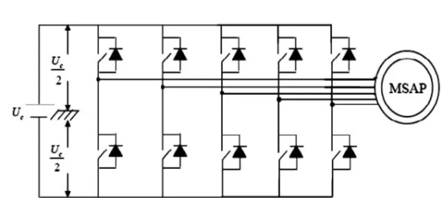
Fig. 1 gives the structure of the studied system. A 5-leg pulsewidth modulation (PWM) inverter [1, 4, 10] supplies a PM 5-phase synchronous machine. The aim of this section is to present, how the 5-phase machine electrical model can be transformed in two 2-phase and one 1-phase equivalent machine models, in order to make the control simple and robust; these machines are magnetically decoupled and mechanically coupled.
The mathematical model of the 5-phase motor that describes the electrical behavior of this machine in a natural base will be firstly presented.
Fig. 1. Schematic of 5-phase PM machine supplied by a VSI drive
The electric equation of a 5-phase PM synchronous machine in the natural base is given by the following expression, (1), for each phase (here the k-th phase).
vk = Rsis+ dΦsk
dt + ek, (1)
where Rsis the resistance of a stator phase, Φskis the stator flux vector created in the k-th phase by stator currents and ekis the EMF induced in this phase by the permanent magnet rotor motion. The hypothesis of non-saturation, no saliency effects and phase angular regularity, makes possible to define a relation between the current vector and the stator flux vector, so we have (2):
Φs= λ(i), (2) [ Lns]= mat (λ, Bn)= M2 L M1 M2 M2 M1 M1 L M1 M2 M2 M2 M1 L M1 M2 M2 M2 M1 L M1 M1 M2 M2 M1 L ,
where L is the self-inductance of one phase, M1 is the mutual inductance between two adjacent phases (electrical shift 2π
5 angle) and M2 is the mutual inductance between two non-adjacent phases (shifted with4π
5 electrical angle).
The magnetic coupling between phases makes the direct control of the machine more complex and, therefore, it is necessary to identify a new frame in which the flux is expressed only according to the currents. In this new frame, the phases are magnetically decoupled by applying the generalized Concordia transform, defined in [6, 11, 12]. In this new frame the inductance matrix [Lns], is in diagonal shape. Hence, (1) can be decomposed in three independent sets of equations in two 2D and one 1D sub-frames. These 3 sets of an electrical equation can be seen as the electrical equations, corresponding to one 1-phase and two 2-phase machines. These three
machines are called a zero sequence machine, primary and secondary machines with [z], [αp, βp], [αs, βs] notations, respectively (3): vz= Rziz+ Λz diz dt + ez vαβp = Rsiαβp+ Λp diαβp dt + eαβp vαβs = Rsiαβs+ Λs diαβs dt + eαβs . (3)
– The zero-sequence sub-system, is characterized by a cyclic inductance Λz. – The main sub-system is characterized by a cyclic inductance Λp.
– The secondary sub-system is characterized by a cyclic inductance Λs. – These inductances are the eigenvalues of the inductance matrix[Lns].
By considering the machine to be star-coupled, the zero sequence component of current is zero. Moreover, it is possible to control the main machine and secondary machine independently, since both machines are magnetically decoupled, the system behaves as if there are two different machines mechanically coupled. In fact, signals (electromotive forces, voltage, currents) are projected by families of harmonics into these sub-spaces. The harmonics 1, 9 and 11 project in the main plane, the harmonics 3, 7 and 13 in the secondary plane and the multiples harmonics of 5 on the homopolar straight (6). It can be easily demonstrated that each time and space harmonics of the current, flux and voltage are associated with a particular sub-system [4, 13], as shown in Table 1. So, we can then consider that the main and secondary machines have p and 3p pairs of poles, respectively. Therefore, the command of the 5-phase permanent magnet motor is made by applying two Park transforms to each of the 2-phase sub-systems (s and p) given by (4). These transforms lead to define two d−q rotating frames, the first one, (d−q)p that corresponds to the first harmonics and rotates atω, and the second one, (d−q)s that corresponds to the third harmonics and rotates at−3ω.
vd p= RsId p− ωΛpIq p+ Ed p+ Λp d Id p dt vq p= RsIq p+ ωΛpId p+ Eq p+ Λp d Iq p dt vds= RsIds− 3ωΛsIqs+ Eds+ Λs d Ids dt vqs= RsIqs+ ωΛsIds+ Eqs+ Λs d Iqs dt . (4)
Expression of the FEM
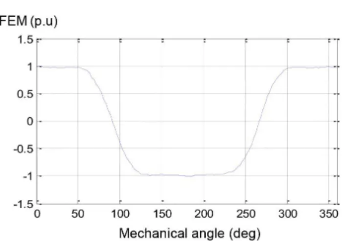
A classical PM machine has trapezoidal EMF. Fig. 2 presents the waveform of the EMF of such a 5-phase PM machine. This EMF waveform corresponds to experimental measurements in a 5-phase PM machine (Fig. 5). Table 1 presents the harmonic contents of this EMF waveform. It shows that the 3rd harmonic is 23% of the amplitude of the fundamental and the 7th harmonic represents 3.5% of the 3rd harmonic.
Fig. 2. Back-EMF of the experimental 5-phase PM-machine
Table 1. Harmonic decomposition of back EMF of one phase
Order of harmonic 1 3 5 7
Relative RMS amplitude 100 23 7.31 0.82
The back EMF vector in the natural frame (phase frame) can be written as:
ek = ∞ ∑ h=1 Ehsin ( h(pθ − (k − 1)2π 5 ) . (5)
Equations of the EMFs in the sub-systems after the generalized Concordia transform are given by: ez = ∑ h Ehsin(hpθ)xz, h = 5, 15, . . . ep= √ 5 2 ∑ hE h(sin(hpθ)x pα− cos(hpθ)xpβ ) , h = 1, 9, . . . es= √ 5 2 ∑ h Eh(sin(hpθ)xsα+ cos(hpθ)xsβ ) , h = 3, 7, . . . , (6)
where Ehis the peak value of the h-th harmonic of the EMF.
Expression of electromagnetic torque
If a wye connection is used, the electromagnetic torque developed by the machine is equal to:
Tem=
e.i
Tem=
e.i
Ω = εi.
Tpand Tsare the torque of primary and secondary machines, respectively, and withε the speed normalized back electromotive force vector:
On the other hand, the mechanical dynamic equation is:
Tem=
e.i
Ω = Tp+ Ts= J dΩ
dt + f Ω. (8)
This set of equations allows characterizing the electromechanical behavior of the studied 5-phase PM machine.
3. Current reference extraction
Generally, in normal operations, the maximum torque per ampere strategy is used to determine the optimal current references of each phase [13]. In a 5-phase PM machine, if this strategy is applied considering (6), only the 1st and 3rd harmonics of the EMF can be used with two rotating frames. In this case, at a steady state and normal mode the current references are constant in the two d–q rotating frames. Thus, it is possible at normal operation to use a PID controller that allows good tracking performances of the current references. In this work, we consider only healthy mode, with two cases of operation. We can control the main and secondary machine simultaneously with different current references. First, the main machine is used alone to produce the torque by imposing a current following the axis-q of the main machine Ipq, then we have:
Ips= 0 A at T0(Ipq = I).
Case 1: constant torque with copper loss minimization. By keeping the same reference torque (T1(I′)= T0), while controlling the two machines simultaneously with new references of currents in order to reduce copper losses, we can write:
T1= T0= Tp′+ Ts′,
T0 = εi = εpqIpq′ + εsqIs′. (9) In order to guarantee the collinearity between the current vector and the FEM, the following ratio is imposed: Isq′ Ipq′ = εsq εpq = 0.23. (10)
From (7) and (8), we deduce that:
Ipq′ = T0 1.053εpq = Ipq 1.053 Isq′ = 0.23Ipq′ . (11)
Case 2: Increased torque to given copper losses. In case 1, we have improved the efficiency of the machine for a given torque. By changing the reference currents of the machine, we will always
Ipq= √ Ipq′′ + Isq′′ . We deduce : Ipq′′ =√Ipq 1.053 Isq′′ = 0.23Ipq′′ . (12)
4. Control scheme
Current control loop
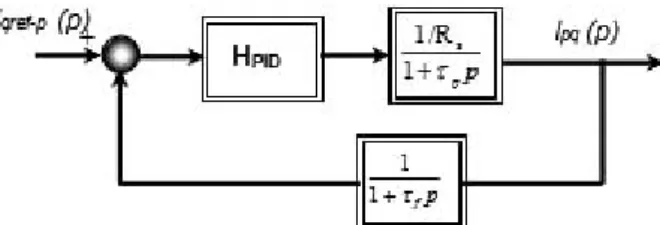
The control loop of the secondary and main machine currents is made in the two d–q rotating frame as defined in paragraph 3. In this case classic controllers are able to track the current references (Fig. 3) which are constants in a steady state, this leads to a constant torque in the steady state. In Equation (4), the crossing terms introduced by the Park transformation and the back-EMFs are considered as disturbances, which can be compensated without difficulty. Based on these equations, the transfer function of an open loop system along the q−axis in the case of the main machine is given by:
G1B0(p)= 1 Rs 1+Λp Rs p , (13) withτp =Λp Rs
as the electrical time constant of the primary machine. The current measurements can be noisy, so a 1st order low-pass filter is associated with the current sensor. Its transfer function is:
GFT(p)= 1
1+ τfp. (14)
Hence, the transfer function of the open-loop system becomes:
G2B0(p)= GFT(p) G1B0(p)=
1
Rs
(1+ τfp)(1+ τpp). (15)
The transfer function of the PID controller is HPIDgiven by:
HPID(p)= 1+ 1 Tip + Tdp 1+Td Np . (16)
By identifying the transfer function in the closed loop as a 2nd order, we determine the parame-ters of a well-tuned PID controller. In our case, the cut off frequency is fixed at
fc = ωc/2π = 1000 Hz and ξc at 0.7. The same control procedure is applied for the sec-ondary machine. We note that when speed increases or in the case of a fault (as open phase faults), classical linear controllers (as PID) cannot provide a correct tracking of the reference in
the natural base or in d–q frames. It is necessary to ensure a good tracking by using non-linear control strategies. The most common non-linear control strategy is the hysteresis control mode, which was implemented with success in [13]. Under an open circuit fault condition, torque rip-ples appear with this classical control. These riprip-ples are linked to the interaction between the non-symmetrical system of currents and the symmetric system of electromotive forces. To avoid these torque ripples, an adaptive method to determine current references is described in [12, 13].
Fig. 3. Block diagram of the current control (Iq–p)
Speed loop control
Fig. 4 shows the control block diagram of the proposed system. The speed controller allows one to maintain the speed at its reference value. From the mechanical equation of the machine, (6), the transfer function of the mechanical system can be obtained as:
Hv(p)= ω Tem = B A = 1 f + Jp, with: Gv(p)= 1 f 1+ τmp. (17)
Fig. 4. Block diagram of speed control by PI controller
Let’s define the mechanical time constant asτm= J
f.
The transfer function of the closed-loop system with the PI regulator is:
G1(p)= GB0(p)HPI(p) 1+ GB0(p)HPI(p) = ( 1+kp ki p ) ki J p2+ f + kp J p+ ki J . (18)
By identifying the closed loop transfer function as a 2nd order function, the controller can be determined as: kp= 2ξ Jωc− f ki = Jω2c . (19)
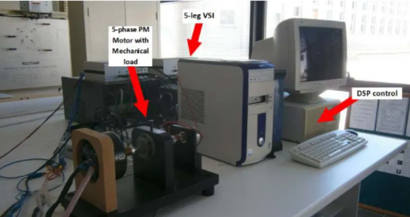
Simulations were carried out in Matlab®/Simulink®environment and compared with exper-imental results. The presented approach has been implemented in a low power experexper-imental set-up. This installation is composed of a 5-phase PMSM with trapezoidal EMF and a 5-leg DSP-controlled VSI drive. The switching frequency of the VSI is fixed at 12 kHz in all the studied cases. Fig. 5 presents a snapshot of this experimental set-up. The overall system is controlled by a DS1005 controller board for DSpace. The sampling time has been set at 100 µs. Figs. 6 to 9 show simulation and experimental results under normal conditions with a PID simultaneous control of two fictitious machines in two d–q frames as presented in theory. We can see that the simulation results (Figs. 6 and 7) are quite similar to the experimental ones (Figs. 8 and 9), apart from the presence of high frequencies due to PWM modulation. Figs. 7 and 9 represent the case of simultaneous control of the two fictitious machines with repartition of the torque between MM and MS. These results show the efficiency of the proposed control strategy in healthy steady state operation. This strategy combined with the PID regulator allows for good tracking of current references and smooth torque in all the studied cases.
Fig. 5. Snapshot of the experimental test-bed (VSI is behind the computer)
(a) (b)
Fig. 6. Simulation results: (a) current in one phase of 5- phase machine; (b) torque (Ts= 0, only main machine is controlled)
(a) (b)
Fig. 7. Simulation results: (a) current in one phase of 5-phase machine; (b) torque
(a) (b)
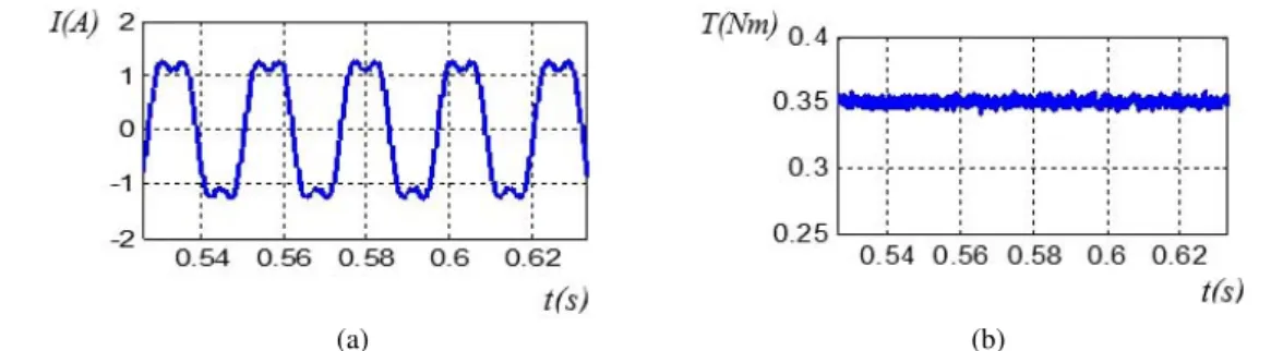
Fig. 8. Experimental results: (a) current in one phase of 5-phase machine; (b) torque (T s= 0)
(a) (b)
Fig. 9. Experimental results: (a) current in one phase of 5-phase machine; (b) torque
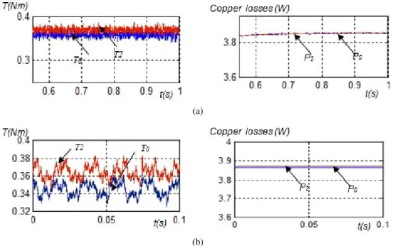
To assess the advantage of using optimal non sinusoidal current references, the main machine is firstly controlled alone by imposing Ipq = −2.4 A and Ips = 0 A corresponding to torque T0. This case corresponds to Figs. 6 and 8. Fig. 10 shows the case of simultaneous control of the two fictitious machines, by fixing the main machine current at Ipq′ = −2.2792 A, and the secondary machine at Isq′ = 0.5242 A corresponding to torque T1, which are presented in paragraph 4 (case 1). The simulation results are shown in Fig. 10(a) and the practical one in Fig. 10(b). It can be seen that the torque is identical to the case when only the main machine is controlled. The copper losses are reduced by 10% compared to the case where the main machine is controlled alone.
Figs. 11(a) and (b) show the simulation and experimental results related to case 2 of para-graph 4. The case of the simultaneous control of the two fictitious machines, by fixing the main
(a)
(b)
Fig. 10. Maximum and constant torque developed (T1 = T0), case 1: (a) simulation; (b) experimental results, P0 – copper losses when only main machine is controlled, P1 – copper losses when main and
secondary machine are controlled in the case
(a)
(b)
Fig. 11. Torque developed at given losses, case 2: (a) simulation results; (b) experimental results, P2 – copper losses when main and secondary machine are controlled in case 2
machine current at Ipq′ = −2.339 A, and the secondary machine at Isq′ = 0.538 A, corresponding to torque T2, which are presented in paragraph 4, case 2. It can be seen that the proposed strategy leads to an increase of the torque by 4% (in comparison with sinusoidal current supply) for the same copper losses.
6. Conclusion
In this paper, the modeling of a 5-phase permanent magnet motor with a trapezoidal back EMF is presented. Then a specific transform is defined to allow easier control of the system. This transform allows using a classic PID controller for the current loops, even if non sinusoidal current references are used in a steady state.
The presented work shows that optimal current references including third harmonic injection can be defined, which allows for the minimization of the Joule losses for a given torque or maximizing the torque for given Joule losses. This strategy leads to a significant improvement of the machine and drive compactness which can be really interesting in very high power applications. These strategies have been validated by both simulations and experimental results obtained using a low power test bench.
The experiment on the test bench (the tested EMF machines are quasi-sinusoidal with a 3rd harmonics of EMF equal to 23% of the first one) has proven that the 3rd harmonic current injection leads to a given torque, to the decrease of copper losses by 10% for a given torque and the increase of the torque by almost 4% for given copper losses, in accordance with the presented theory. The paper shows that the used PID controllers can be tuned by a classic method. Both experimental and simulation results show good static and dynamic performances. These results highlight the pertinence of the adopted strategies.
Notation
N= 5 Number of phases
Φsk Stator flux vector created in the k-phase
ek EMF induced in the k-phase by the permanent magnet rotor flux vz, iz, ez Voltage, current and EMF vectors of zero sequence frame vαβ−p Voltage vector in the main 2-phase frame
iαβ−p Current vectors in the main 2-phase frame
eαβ−p EMF vector in the main 2-phase frame vαβ−s Voltage vector in the secondary 2-phase frame
iαβ−s Current vectors in the secondary 2-phase frame
eαβ−s EMF vector in the secondary 2-phase frame
References
[1] Parsa L., Toliyat H.A., Five-Phase Permanent – Magnet Motor Drives, IEEE Transactions on Industry applications, vol. 41, no. 1, pp. 30–37 (2005).
[2] Dwari S., Parsa L., An Optimal Control Technique for Multiphase PM Machines Under Open – Circuit Faults, IEEE Transactions on Industry Electonics, vol. 55, no. 5, pp. 1988–1995 (2008).
(2004).
[4] Locment F., Semail E., Kestelyn X., Vectorial Approach Based Control of a seven- phase Axial Flux Machine Designed for Fault Operation, IEEE Trans on Ind. Electronics, vol. 55, iss. 10, pp. 3682–3691 (2008).
[5] Toliyat H.A., Waikar S.P., Lipo T.A., Analysis and simulation of five phase synchronous reluctance machines including third harmonic of airgap MMF, IEEE Transactions on Industry applications, vol. 34, no. 2, pp. 332–339 (1998).
[6] Martin J.P., Pierfederici S., Meibody T., Letellier P., Synthèse des méthodes de filtrage du couple des MSAP Polyphasées en modes normal et dégrade, European Journal of Electrical Engineering, vol. 10, no. 1–2, pp. 117–149 (2007).
[7] Parsa L., Toliyat H.A., Sensorless Direct Torque Control of Five Phase Interior Permanent Magnet Motor Drives, IEEE Transactions on Industry applications, vol. 43, no. 4, pp. 952–959 (2007). [8] Kestelyn X., Modélisation vectorielle multi-machines pour la commande des ensembles convertisseurs
machines polyphasés, Ph.D. thesis, University of Sciences and Technologies of Lille (2003). [9] Semail E., Kestelyn X., Bousscayrol A., Sensitivity of a 5 phase Brushless DC machine to 7th harmonic
of back-electromotrice force, PESC 2004 IEEE Power Electronics, CD-ROM, Germany (2004). [10] Dehault E.R., Modélisation dynamique, commande et conception de machines pentaphasées alimentées
par des onduleurs MLI, Ph.D. thesis, Universty of Sciences and Technologies of Nantes (2005). [11] Gataric S.A., Polyphase Cartesian Vector Approach to Control of Polyphase AC Machines, IEEE
Transactions on Industry applications, vol. 3, pp. 1648–1654 (2000).
[12] Kestelyn X., Generation of on line optimal current references for multi-phase permanent magnet machines with open circuit phases, Proceedings IEMDC 2009, Miami, USA, pp. 689–694 (2009). [13] Mekri F., Charpentier J.F., Kestelyn X., Semail E., Etude comparative de différents correcteurs pour
la commande optimale avec défauts d’une machine pentaphasée, European Journal of Electrical Engineering (EX RIGE), vol. 15, no. 4, pp. 377–400 (2012).