A Distributed Control Network
for a Mobile Robotics Platform
by
Seain P. Adam
Submitted to the Department of Electrical Engineering and Computer Science
In Partial Fulfillment of the Requirements for the Degree of
BACHELOR OF SCIENCE IN ELECTRICAL SCIENCE AND ENGINEERING
and
MASTER OF ENGINEERING
IN ELECTRICAL ENGINEERING AND COMPUTER SCIENCE
at the
MASSACHUSETTS INSTITUTE OF TECHNOLOGY May 1996
© 1996 Seain Patrick Adam
All rights reserved
1
If>
Department of Electrical Engineering and Computer Science May 18, 1996
d by
Dr. David Kang -.,' / // ~-S.hnical Supervisor
0A Al Professor Gill Pratt
A 1 t Thesis Supervisor
by I ' '
;1VASSACHUSETTS INST' lUTE
OF TECHNOLOGY
SF.R.
MorgenthalerChairman, De-r nt Committee on Graduate Theses
JUN
1
1
1996
LIBRARIES AuthorApprove
Certif~ed b
Accepted ------A Distributed Control Network
for a Mobile Robotics Platform
by
Sean P. Adam
Submitted to the
Department of Electrical Engineering and Computer Science May 18, 1996
In Partial Fulfillment of the Requirement for the Degree of Bachelor of Science in Electrical Science and Engineering
and
Master of Engineering in Electrical Engineering and Computer Science
ABSTRACT
Tests carried out on the Unmanned Vehicle Laboratory's initial prototypes: the MITy series; the MITe series; and Companion, revealed that the traditional architectures normally implemented on mobile robotics platforms are not practical for design, manufacturing, or system control. The major drawback of all of these prototypes was that their control systems were designed using sensor fusion. This required a central controller to assimilate all the sensor data before it could be acted upon. This was undesirable due to the limited amount of processing that could be dedicated to higher level control. A system needed to be designed that possessed: support for
distributed processing; a predefined hardware interface to allow for parallel development; attributes allowing for upgradability and adaptability; and plug-and-play capabilities. Research showed that such a system could be built using smart node technology. With a smart network, each sensor and actuator possess its own independent processor and signal conditioning circuitry and acts as a separate node on a local network. By transforming from a traditional direct wired central controller system to a smart node networked system, a more efficient robot architecture was obtained.
Technical Supervisor: Dr. David Kang
Unmanned Vehicle Laboratory Supervisor Thesis Supervisor: Dr. Gill Pratt
grandfather and namesake John Patrick Hayes Husband, Father, and Patriot He labored to guarantee his children and his children's children a better life. Though I never had a chance to know him, I was raised with stories of his life and his deeds and I can only hope to one day be the man that he was.
ACKNOWLEDGMENTS
I would like to acknowledge all of the men and women I have had the opportunity and pleasure to work with over the years on this project. I would like to thank the following: William Kaliardos and Shane Farritor for being there that cold rainy night in Faneuil Hall. Terence Chow and Steve Steiner for putting up with my Irish temper and my ranting and raving about things beyond all of our control on the Companion and EOD
prototypes. Jim Dyess, Bryan Koontz, and William McFarland for supporting me when push came to shove and decisions needed to be made.
I would especially like to thank Pehr Anderson, Charles Tung, and Ely Wilson for the help and support they gave me in setting up and using the Echelon network and developing the prototype smart nodes. Without them my research would not have been possible.
I would like to extend my gratitude to Dr. David Kang who gave me the opportunity to research this thesis and who always forced me to work to my potential. I would like to thank Professor Gill Pratt for taking the time to read and critique this paper. I would also like to thank Anne Hunter for her
continued support, guidance, and friendship throughout my MIT career. I give my greatest thanks and love to my mom and dad, my brother Warren, and my grandmother Elizabeth Hayes for always believing in me and for giving me a place that I can always call home.
I also want to thank Jill whose love and support acted as my guiding light throughout this work.
Finally, I want to thank my Lord and Savior for catching me when I stumbled and carrying me when I fell. Without him, none of this would have been possible.
Thank you all.
Publication of this thesis does not constitute approval by Draper or the sponsoring agency of the findings or conclusions contained herein. It is published for the exchange and stimulation of ideas.
I hereby assign my copyright of this thesis to The Charles Stark Draper Laboratory, Inc., Cambridge, Massachusetts.
Seain Patrick Adam
Permission is hereby granted by The Charles Stark Draper Laboratory, Inc., to the Massachusetts Institute of Technology to reproduce any or all of this thesis.
TABLE OF CONTENTS
Abstract ... 3 Acknowledgements...5 Table of Contents ... ... 7 List of Figures ... 10 List of Tables ... 11 Chapter 1: Introduction ... 12 1.1. Motivation: ... 12 1.2. O bjective: ... 13Chapter 2: Draper Unmanned Vehicle Laboratory Prototypes ... 14
2.1. The MITy Series - Robots for Planetary Exploration...14
2.1.1. Basic MITy Structure:...15
2.1.2. MITy-1 -- A Proof-of-Concept: ... 16
2.1.3. MITy-2 -- A Working Autonomous Prototype: ... 17
2.1.4. MITy-3-- A System Redesign: ... 19
2.2. Companion -- Advanced Robotics Platform for Sensor Fusion :...21 2.3. MITes -- Nano-Architecture: ... 23 Chapter 3: 3.1. 3.2. 3.3. 3.4. Control Architecture Theories ... 25
Horizontal and Vertical Decomposition: ... 25
Brook's Subsumption: ... 27
Payton's Reflexive Control System:...29
4.1. MITy Prototype Series: A Direct-wired Transducer Platform:...34
4.2. MITe Prototype Series: A Bus-based Transducer Platform: ... 36
4.3. Companion Prototype:... 38
4.4. Summary of Advantages/Disadvantages of UVL Systems: ... 40
Chapter 5: Smart M odules ... ... 43
5.1. Overview of Sm art Sensors:... .... 43
5.2. Smart Modules -- A Flexible Control Architecture: ... 48
Chapter 6: Operating Network Protocol... ... 53
6.1. Sensor/Actuator Buses and Communication Protocols: ... 53
6.2. LonWorks Architecture: ... 55
6.2.1. Smart Networks: ... 55
6.2.2. Network Variables and Explicit Messages: ... 55
6.2.3. LonWorks Smart Nodes: ... .... 57
6.3. LonTalk Protocol:... ... ... 59
6.3.1. Open System Interconnection Standard: ... 59
6.3.2. LonTalk Addressing and Routing:... 59
6.3.3. LonTalk Communication Services:... 61
6.4. Motorola/Toshiba Neuron Chip:...63
Chapter 7: 7.1. 7.2. 7.3. 7.4. Proposed System Architecture ... ... 66
Distributed Intelligence: ... 66
Sensor-Actuator Communication Control: ... 68
Competence through Sensor Priority (future work):...71
Chapter 8: Implementation of Smart Sensor Architecture ... 76
8.1. Smart Module Demonstration: ... 76
8.1.1. Explanation of Demonstration Control System:...76
8.1.2. Smart Nodes and Network Variables: ... 82
8.2. Poseidon - A Smart Sensor Surf-Zone Vehicle (Future Work): ... ... 85
Chapter 9: Conclusions and Recommendations... ... 86
9.1 Smart Sensor Technology: ... 86
9.2 Echelon LonWorks Networking Protocol:... .... 87
9.3 Future Research: ... ... 88
References ... 90
A ppendix:.... ... ... 92
A.1 Demonstration Sonar Code:... ... 92
A.2 Demonstration Thruster Code: ... .... 98
2-1. Basic M ITy Structure... ... 15 2-2. M ITy-1... 16 2-3. M ITy-2... 18 2-4. M ITy-3 ... 20 2-5. Companion Prototype ... 23 3-1. Horizontal Decomposition... 25
3-2. Control Layout for a Subsumption Architecture ... 26
3-3. Reflexive Control System... 31
3-4. A N etw ork U nit... ... 33
4-1. Traditional Centralized Processing Architecture ... 34
4-2. MITe Prototype Bus Architecture ... ... 37
4-3. Companion Multiple Processor Architecture... ... 39
5-1. Smart Node Architecture ... 45
5-2. D ata Path... 46
6-1. LonW orks N etw ork... ... 55
6-2. Block Diagram of LonWorks Node... ... 58
6-3. LonTalk Addressing Hierarchy ... ... ... 61
6-4. Block Diagram of MC143150... 64
7-1. Priority-Level based Smart Network... ... 72
7-2. Tw o Robot N etw ork ... ... 74
8-1. Demonstration Network ... 77
8-2. Obstacle Avoidance Hemispheres ... ... 79
8-3. Obstacle within Safety-Radius ... ... 80
8-4. Possible Hazards Encountered by Robot... ... 81
LIST OF TABLES
4-2. Advantages/Disadvantages of UVL Systems ... 42
5-1. Sm art N ode Properties ... 48
5-2. Advantages/Disadvantages of Smart Sensor System... 51
6-1. Echelon Transceiver Types... 57
6-2. LonTalk Protocol Mapping onto OSI Model ... 59
6-3. Channel Throughput ... 60
6-4. Neuron Chip I/O Objects... 65
INTRODUCTION
CHAPTER 1
1.1. Motivation:
In 1990, the Draper Planetary Rover Baseline Experiment (PROBE) Laboratory was started to research, design, and manufacture an autonomous micro-rover for planetary exploration. The initial rovers were designed around specifications set by NASA for its MESUR Pathfinder mission. The first rover prototype (MITy-1) was a proof-of-concept platform. It was equipped with an earthbound sensor suite including three acoustic range finders and a compass. After analyzing the test data from MITy-1, a second prototype was built. Where MITy-l's control system was completely reflexive with no path planning behavior, MITy-2's control system assimilated all of the sensor data to allow for complete path planning behavior. Only sensors that could be used for exploration of the Moon or Mars were employed. These included a laser range finder for long range hazard avoidance,
proximity sensors for cliff detection, a gyro and a sun sensor, inclinometers for 3-dimensional navigation, and tachometers for speed control. Both were fully functioning autonomous robot prototypes. Analysis of MITy-2's
mechanical platform led to the design of MITy-3. Though never fully
autonomous, MITy-3 allowed for research into various methods of steering. To alleviate loading on the processor caused by complex motor control code, MITy-3 implemented its motor control in hardware.
Due to the success of the PROBE Lab's MITy-series, Draper decided that more research should be carried out in the area of robotics and autonomous control systems. The Unmanned Vehicle Laboratory (UVL) was formed in 1994. UVL's task was to investigate possible applications for autonomous and semi-autonomous robots and determine how best to meet the necessary
Chapter 1: Introduction
requirements of those applications. The first study dealt with the design of a sensor fusion package that would allow for the autonomization of almost
any vehicle. The test platform, known as Companion, was an electric wheelchair. The Companion control system was designed around an 486 Laptop running the higher level path planning control code and a Ampro-386 board to handle the assimilation of all of the sensor data. This was an
improvement over the MITy architecture which only utilized a Zilog-180 microprocessor board for data processing and path planning.
1.2. Objective:
The knowledge gained from working with Companion prompted UVL to begin researching the possibility of designing a system which would be easier to build, easier to modify, and able to make use of the best features of the MITy and Companion prototype series. This thesis is divided into three different areas of research and development:
* Research of various proposed control architectures for robot systems. This research also includes studying the current UVL prototypes to determine their advantages and disadvantages.
* Research into the use of smart nodes to improve upon the traditional control architectures normally used in robot design.
* Implementation of a simple smart node system.
The objective of this research is to determine a method by which a more robust and efficient robot platform can be designed and manufactured.
DRAPER UNMANNED VEHICLE
LABORATORY PROTOTYPES
CHAPTER 2
2.1. The MITy Series
--
Robots for Planetary Exploration
In 1990, the newly founded PROBE lab, under the direction of Dr. David Kang, began a system study to determine what was necessary to design and build a robot for planetary exploration. This initial study was completed in June 1992 [1]. It was determined that a successful planetary robot would have to be small, robust, and most importantly completely autonomous. Three prototype robots were designed and built based off the findings of this
study: MITy-1, MITy-2, and MITy-3.
The planets considered in the initial study were the Moon and Mars. Though tele-operation is possible for a lunar robot, the time to communicate with a robot on Mars, best case 40 minutes, necessitates a high degree of
autonomy for the robots. The robot needs to be able to navigate through an unknown environment while avoiding obstacles and pitfalls; all the while, maintaining a sense of where it has been, where it currently is, and where it wants to go. To accomplish these tasks, the robot requires a complete hazard avoidance and navigation sensor package. The robot also needs a
microprocessor capable of processing and fusing all the sensor data for use by the control system. Finally, the robot needs a stable and dependable power supply that will last the entire mission. The MITy prototypes use
rechargeable nickel-cadmium batteries and solar panels to restore on-board power.
Chapter 2: Draper Unmanned Vehicle Laboratory Prototypes
2.1.1. Basic MITy Structure:
There were a number of design characteristics that were maintained in all the prototypes. Each rover was based upon a three-platform frame
interconnected by two flexible steel rods. These rods allowed for flexibility in pitch and roll but not in yaw. The basic MITy structure is shown in Figure 2.1
[2].
rover platforms
flex
flex in roll
5>
SlIlMUIC ZLCOL I UUZFigure 2-1. Basic MITy Structure
Since the rover is meant to move forward and backing up is only done when necessary to avoid an obstacle, the front platform is dedicated to the hazard avoidance sensors. The middle platform holds the processor package and all the navigational sensors. The rear platform is used to hold battery packs, solar cells, and any mission science packages.
There are two wheels on each platform. Actuation is provided by motors within each of the wheels. MITy-1 and MITy-2 use an Ackerman steering system similar to that used on automobiles. MITy-3 makes use of differential speed control where the wheels are attached to a free pivoting axle
[2]. Assuming that the failure of any two motors does not produce drag on the robot, any combination of four wheels will be enough to move the robot.
2.1.2. MITy-1 -- A Proof-of-Concept:
MITy-1 was designed as a proof-of-concept prototype to demonstrate that the PROBE lab was capable of manufacturing a fully autonomous robot. A block diagram of MITy-1 can be seen in Figure 2-2. MITy-1 is 26" long, 13.4" wide, and weighs approximately 8.9 kg.
processor acou! senso bumpers & feelers >atteries drag wheel
7
batteriesFigure 2-2. MITy-1
To minimize the cost and the development time, only earth-based sensors were implemented on this prototype. Navigation was performed using a drag wheel to measure distance traveled and a compass to determine vehicle heading. Using dead reckoning, these sensors allow the robot to determine its position relative to where it began. Long range hazard avoidance was provided by three Polaroid acoustic range-finders while mechanical feelers and bumpers provided more localized obstacle
information. The sonars where mounted on the front platform of the robot and were set at angles to allow full coverage of the robot's forward path. The mechanical feelers were mounted on either side of the front platform and extended out past the wheels. Bumpers where mounted on the front and rear
Chapter 2: Draper Unmanned Vehicle Laboratory Prototypes
platforms and acted as a last resort if the sonars and feelers failed to detect an obstacle.
A 68C11 board was used as the central controller. Due to the board's limited processing capabilities, a relatively simple reflexive control system was implemented on the robot. The robot also possessed a video and data transmitter to allow control by a PC-based ground station. Initial tests demonstrated that the robot was able to perform simple autonomous tasks without external intervention. When given a destination 100 meters away, the robot was able to arrive within 10 meters of the designated point. This was well within the mission criteria set by NASA's Jet Propulsion Laboratory.
2.1.3. MITy-2 - A Working Autonomous Prototype:
Using the knowledge and experience gained from designing, building, and testing MITy-1, the development of a more advanced prototype, MITy-2, was initiated. A number of factors were considered during the design of MITy-2. The sensor suite would have to be geared more towards an
unknown, hostile, planetary environment. Where MITy-1's sensors allowed only 2-dimensional navigation, MITy-2 would be expected to travel through a 3-dimensional environment. Since the reflexive control implemented on MITy-1 would not be sufficient for traversing the Martian landscape, a more powerful processor would have to be used to implement sensor fusion, path planning, and terrain mapping on board the robot. Also, the MITy-2
prototype would have to be more robust than its predecessor. A picture of MITy-2 can be seen in Figure 2-3.
Inclinometers
Sun Sensor
I X
/
Figure 2-3. MITy-2
It was decided that hazard avoidance would be performed using laser range-finders, infrared proximity sensors, and mechanical bumpers. The most important reason for choosing infrared lasers over acoustical sensors was because acoustic sonars require an atmosphere to act as a medium for the transmission of the sound wave. However, laser range-finders can work in the void of space as well as on Earth. Also, the laser range-finder used for long distance hazard avoidance gave more accurate data than the acoustical sonars used on MITy-1 that suffer from false reflections. Infrared proximity sensors were used for cliff detection to guarantee that the robot did not
damage itself by driving off high embankments. The mechanical bumpers act as a last line of defense for the robot. If an obstacle was not detected by the laser range-finder or the control system was unable to maneuver correctly around the object, then the bumpers will be activated and the robot will reverse direction.
For navigation, MITy-2 was outfitted with a mechanical rate-gyro, inclinometers and accelerometers, a sun sensor, and a non-powered
drag-Chapter 2: Draper Unmanned Vehicle Laboratory Prototypes
wheel. The gyro was used to keep track of the heading of the robot.
Unfortunately, the gyro suffers from a large amount of drift that causes errors in navigation information. This was the reason that a sun sensor was also used. The sun sensor monitors the angle of the sun in comparison to the robot. By referencing both the gyro data and the sun sensor data, errors were usually removed. The control system was also designed to deal with the fact that either sensor could return totally inaccurate data that should be ignored. The inclinometers and accelerometers were used to monitor the pitch and roll of the robot's three platforms.
2.1.4. MITy-3-- A System Redesign:
While testing continued on MITy-2, a new design effort was
undertaken to upgrade the overall MITy mechanical/electrical system. The third prototype, MITy-3, was never outfitted with any sensors. It was decided that MITy-2 had proven the labs ability to design and build a completely autonomous robot. MITy-3 was mainly an improvement on the hardware structure. Even though MITy-2 had been a step in the right direction for the design of a planetary micro-rover, there were still a number of system
characteristics that would never allow the MITy system to be spaced qualified. MITy-3 can be seen in Figure 2-4.
Iha
whicl
micro
(PWN
negat
of the
the ar
highe
steerh
Moto]
ical fa
found
moun
Figure 2-4. MITy-3
Two of the greatest flaws that MITy-2 possessed were the methods by which motor control and steering were performed. On MITy-2, the
microprocessor was responsible for outputting pulse-width modulation
(PWM) signals to drive each of the motors. Steering was performed by servos normally found on remote control racing cars. These attributes had a
negative affect on both the hardware and the software of the robot. Creation of the PWM signals placed a significant load on the processor which reduced the amount of processing that could be directed toward sensor fusion and higher level control. The trade off between sharing processor time with the
steering and the control system allowed MITy-2 to have only eight possible motor speeds. The use of "hobby" grade servos led to a number of mechan-ical failures during testing. It was concluded that a solution needed to be found that would alleviate both problems.
Instead of a servo for steering, the MITy-3 front and rear wheels were mounted to axles that could pivoted freely about their center. Steering was
)n
Chapter 2: Draper Unmanned Vehicle Laboratory Prototypes
performed by using differential speed control. After initial testing of this concept, an additional motor was added to the rear and front platforms to act as a clutch for the free pivoting axle. These motors did not aid in the steering of the robot; however, they locked the axles in place when the correct angle of turn had been achieved.[2] The amount of control necessary for this method of steering required precision motor control. The eight speeds offered by the MITy-2 motor control would not be sufficient to implement differential speed control. A new circuit was designed to allow better control of the motors. The final circuit was able to output 256 different PWM signals. Due to the motors' electrical and mechanical characteristics, these 256 PWM signals translated into approximately 20 noticeable motor speeds. However, these were enough to implement the new steering concepts.
2.2. Companion
--
Advanced Robotics Platform for Sensor Fusion:
The early nineties saw a decrease in money being spent by Congress on space research. Consequently, a new source of income needed to be found byUVL. Market research determined that opportunities existed in the area of
autonomous and semi-autonomous robotics platforms for Earth based
applications. It was decided that the future of UVL lay in researching the area of sensor fusion. Instead of focusing on one particular application, UVL would begin designing a generic robotics platform controller that would have the capability of making any vehicle semi - autonomous to autonomous. A remote control wheelchair frame was used as the mobile test platform for the sensor fusion package. There were a number of differences between the MITy and Companion prototypes. Most importantly, the MITy prototypes had to be small and inexpensive. Consequently, many of the components had to be specially designed to fit these constraints. Fortunately, it was determined that
Companion would not suffer from the same issues. This allowed UVL to outfit the robot with off-the-shelf components that were not available to the MITy series.
The entire idea behind the Companion project was that the problems normally experienced due to sensor fusion could be removed by using multiple processors. Initially it was decided that Companion would possess up to three processors running in parallel just to deal with the fusion of the sensor's data. The higher level control system and path planner were run on a PC laptop. Communication between the laptop and the fusion-processors was carried out through ethernet lines. The robot basically become a mobile
LAN. A ground station was also be used to control the robot via a RF modem
link.
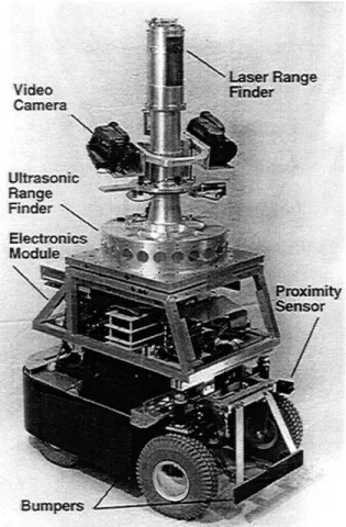
Companion was completely outfitted with both navigation and hazard avoidance sensors. From the knowledge ascertained from the MITy series, a ring of 24 acoustic sensors was used to allow for obstacle avoidance and environmental mapping. To increase the accuracy of the map created by the acoustic sensors, a sophisticated laser range-finder system was also imple-mented. The laser system scanned 3600 around the robot and had a vertical range equivalent to the height of the robot. Companion also possessed two video cameras that had the same scanning ranges as the laser system. These cameras were used to aid in tele-operation and also for recording necessary information of the surrounding environment. Additional hazard avoidance was supported by bumpers and short range proximity sensors to act as a last line of defense in case an obstacle was not detected by the sonar ring and the laser system. Navigation was performed using dead reckoning based off data from an on-board gyro and the encoders on the front wheels. Future plans
Chapter 2: Draper Unmanned Vehicle Laboratory Prototypes
include the addition of a GPS system. Figure 2-5 is a picture of the Companion Sensor Fusion prototype.
Figure 2-5. Companion Prototype
2.3. MITes
--
Nano-Architecture:
Another avenue that UVL began researching was the creation of nano-robots. These robots would be smaller than the MITy series and would be designed for tight areas; such as, nuclear reactors. The objective was to design a simple and inexpensive robot to be used in situations where the robot may be damaged or destroyed. Working with the MITy and Companion
prototypes had shown the UVL engineers the importance of modularity and testability for a robot system. It was decided that the MITes would be a bus-based architecture. By defining the hardware interface between the
transducers and the central controller, it was hoped that it would become easier to maintain and upgrade the sub-systems on the robot.
The MITes hazard avoidance system was based off a single rotating acoustic sensor and bumpers. The acoustic sensor scanned the entire area in front of the robot to guarantee obstacle avoidance. Since the MITes were designed to be an Earth-based robot, navigation was carried out through dead-reckoning using a compass and encoders on the front wheels. Unlike the MITy series where the robot's platform was specially design, the MITes were built around off-the-shelf RC model race cars.
Chapter 3: Control Architecture Theories
CONTROL ARCHITECTURE THEORIES
CHAPTER 3
3.1. Horizontal and Vertical Decomposition:
The hierarchy of a robot can either be setup in a horizontal or vertical
decomposition. Figure 3-1 shows the traditional horizontal decomposition of an autonomous robot's control system.
Sensor Data
Actuators
Figure 3-1. Horizontal Decomposition
As can be seen, the sensory data is passed into the Assimilation Stages where the processed data is put into a usable format. The processed information is then sent to the Planning Stages where the control system determines what must be done to achieve the predetermined objectives set by the user. The Planning Stages then issue a Control Signal to the actuators. There are a number of disadvantages to using the horizontal approach. Each layer of the control system requires the assimilated data from the preceding layer. This causes two problems. First, since all sensory data must pass through each consecutive layer (or module), the control system has "an unavoidable delay in the loop between sensing and action." Second, horizontal decomposition places limitations on the flexibility of the system. If modifications to a
particular module cause that module's I/O requirements to change, then the I/O of the adjacent modules may also change. At best, these will be the only
necessary changes. However, altering the I/O of the adjacent modules may cause a domino affect throughout the control system that requires a
reworking of all the layers' interfaces. These are problems that are not normally seen when using a vertical decomposition.
With a vertical decomposition approach, the transducers are connected in parallel. Figure 3-2 shows the traditional vertical
decomposition. Slevel 3
level 2
level 1
Sensors
I
Actuators
Figure 3-2. Control Layout for a Subsumption Architecture
The sensory data is assimilated at varying levels of complexity; however, unlike the horizontal decomposition, each level of assimilation and planning can be bypassed by the other levels. Vertical decomposition also allows for the possibility of using Command Fusion instead of Sensor Fusion. Command Fusion lacks the generality normally given by Sensor Fusion, but it does allow the control system to exploit low level sensor data for
immediacy. This ability to quickly access sensory data allows for reflexive control of the robot. The vertical approach leads to greater flexibility in the architectural design of the control network. Since each layer is connected in
Chapter 3: Control Architecture Theories
parallel, the altering of one assimilation/planning module will have very little affect on the other modules. Not only does this make the system easier to modify but it also gives the ability to connect different assimilation/
planning modules without altering the overall system design.
3.2. Brook's Subsumption:
In 1986, Brooks [3] theorized that the control system of a mobile robot could be divided into different layers of task-achieving behaviors. With each additional layer, the robot achieves a greater sense of competence. The
interaction between each layer is very important to the control of the robot. The control system must be responsive to high priority goals, while still servicing necessary "low-level" goals.
This concept of multiple goals is considered one of the four main requirements of an autonomous mobile robot's control system. The next requirement revolves around the use of multiple sensors on the robot. The control system must be able to make decisions based off the outputs of the various on-board sensors. Since some of the sensors may overlap in the physical quantities that they measure, inconsistent readings are possible and the control system must be able to determine which reading, if any, is correct. Also, many sensors' outputs do not have a direct correlation to any physical quantity. The third requirement for the robot's control system is robustness. The control system should be able to handle the failure of sensor systems without a complete loss of the control system's integrity. Finally,
extendibility is important for the continued evolution of the robot's control system. Extendibility defines the ability to add more sensors and capabilities to the robot without impairing the speed and performance of the control system. Extendibility can normally be achieved by three basic methods:
* Utilizing previously unused processor power
* Upgrading the processor to achieve a faster overall system * Adding more processors to carry increased load
The idea of subsumption bases each layer of control off of a level of competence. Traditionally the level of competence of a robot has been divided into five main pieces: sensing, mapping, planning, task execution, and motor control. This hierarchical method requires that each of these items exists to some extent before the robot can move. Any change in a single piece may affect the pieces adjacent to it and require a complete redesign of the robots control architecture. This is regarded as a decomposition of the
problem into horizontal slices. Brooks theorized that it is better to decompose the problem vertically where each vertical slice is a different level of
competence. These levels of competence were defined as:
0) Avoid contact with objects
1) Wander aimlessly around given environment
2) Explore the given environment
3) Build a map of environment and path plan 4) Monitor changes to the environment
5) Identify objects and carry out tasks based on these items 6) Plan changes to the state of the given environment 7) Reason about behavior of objects in environment
Layers of the control system would be built to correspond to these levels of competence. The robot is initially designed to fulfill the requirements of a zero competence level. The next layer implements a competence level of one. This layer is able to examine data from the level 0 system and is able to suppress level O's normal data flow. This process is repeated through all the
levels of competence and each new control layer subsumes the roles of the lower levels. Hence, the term subsumption architecture. Robustness is achieved by the fact that all the control layers are setup in parallel with each
Chapter 3: Control Architecture Theories
other (see Figure 3-2). The obvious way to handle the problem of extendibility is by giving each layer its own processor.
Each of these processors acts as a finite state machine that runs
asynchronously from each other. Because there is no handshaking between the processors, it is possible to lose messages. There is no other form of communication between processors and there is no shared global memory within the system. Input to the modules can be suppressed and outputs can be inhibited which allows for subsumption by higher level layers.
3.3. Payton's Reflexive Control System:
Payton's [4] architecture was designed to take advantage of both the immediate and assimilated data provided by the robot's sensors. Payton argues that the data from the sensors is only useful as long as it does not become obsolete before the control system can use it. This requires that the sensors' data is processed as quickly as possible. The challenges placed upon a control system by constantly changing terrain may be to overwhelming for the processing units unless appropriate tradeoffs between immediacy and assimilation are made.
Both assimilation and immediacy have a number of advantages and disadvantages. The assimilation of data allows for the enhancing the completeness and detail of a constructed world representation with added processing. This will allow for easier high-level planning by the control system. However, assimilation requires a great deal of time to obtain the results. In the time necessary to assimilate the data, the robot may actually have already collided with a potential obstacle. Immediacy allows for a quicker access time to the sensory data. The faster the sensor's output can be used the "more value it has for control." This faster access time to the sensor arrays and planning system basically allows the environment to act as the
feedback signal to the control system. Also, the greater the immediacy a control system possesses the easier it is for the system to monitor unexpected changes in the environment. However, in unconstrained environments, robots that employ control systems based around immediacy tend to suffer limited operation. This is due to the fact that "immediate data loses value in loosely constrained environments." It becomes hard to maintain complete control within an environment where moving objects exist. For example, a robot is navigating through an environment where there are people walking in and out of its sensor range. With a reflexive control system, the robot will try to avoid these moving objects. Unfortunately, the robot will soon become
disoriented. If all the robot is meant to do is wander throughout the environment and avoid obstacles, then use of immediacy will be fine.
However, if the robot is supposed to achieve a specific goal, such as traveling to a particular point, the immediacy can lend itself to errors in the control system. Without extremely sophisticated sensors, it becomes difficult for the robot to maintain position information when reflexive hazard avoidance is being implemented.
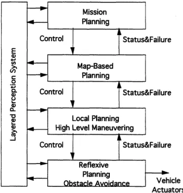
Payton's reflexive architecture was designed around four major modules (see Figure 3-3). The Reflexive Planning module requires the highest degree of immediacy while the Mission Planning module requires the highest degree of assimilation. Since the modules are setup in a vertical decomposition approach, the control system is able to perform both
Chapter 3: Control Architecture Theories
cle
Actuators
Figure 3-3. Reflexive Control System
The higher levels of the control system pass "constraints and specialization commands" downward while failure and status reports are passed upward by the lower level modules. Payton uses a "common blackboard" approach for communication between modules. When one module needs to commu-nicate to another module, it writes its message to a "blackboard" that is accessible by the entire network. Each command issued to the blackboard is passed through a command arbitration unit which determines the priority of the message and issues them to the actuators. In a highly parallel machine architecture. Due to the vertical decomposition of the architecture, the addition of new modules will not alter the currently existing system to any great degree. Unlike Brook's architecture, the vertical layers are based off of assimilation/ immediacy instead of level of competence. To actually increase the level of competence of Payton's control system would require the
Also, a higher level of competence may require modifications to existing modules.
3.4. Rosenblatt and Payton's Fine Grained Architecture:
Both Rosenblatt and Payton [5] believed that Brook's subsumption architecture [3] advocated principles of system design crucial to the creation of a robot controls system. Like Brooks, they designed their system around the
idea of vertical decomposition. However, they also believed that Brook's architecture possessed major practical limitations.
Interestingly enough, one of the major flaws that Rosenblatt and Payton found with the subsumption architecture was the fact that one command could subsume another command. They argued that whenever one command totally inhibited another command all of the data contained by the subsumed command was completely lost. Due to this loss of data, there was no guarantee that the behaviors will be able to perform the functions that were expected of its level of competence. Another drawback evolved from implementing each layer of competence with finite state machines. They argued that these finite state machines possessed internal states that could not be accessed by the other layers. With the addition of each new layer of
competence, the demands on the lower layers increased and the need arose to modify the behaviors of the existing layers. These modifications were made impossible by the internal state of the finite state machines.
Rosenblatt and Payton's solution to these problems was to create a system designed around fine-grained behaviors. Each behavior was divided into a collection of very simple decision-makings units. By making them fine-grained, no unit possess any internal state that could not be accessed by the external network and each unit represented a specific concept for the
Chapter 3: Control Architecture Theories
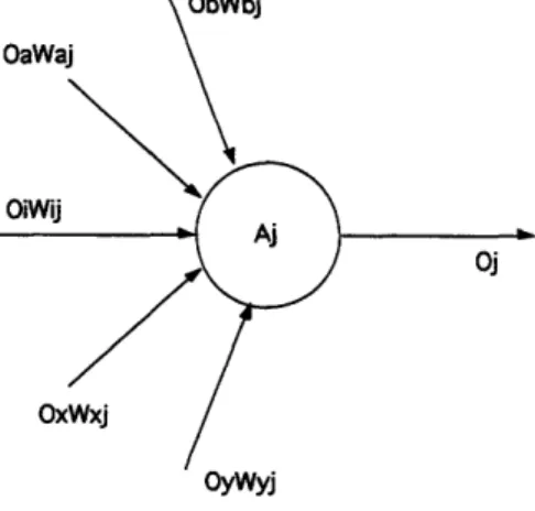
behavior of the robot. Instead of inhibiting commands, they decided that a weight would be applied to each command. Accordingly, no data was ever lost which allowed the system access to all sensory data to make a decision. Where Brook's architecture would have subsumed a command from a lower level of competence, Rosenblatt and Payton's architecture would just attach a lesser weight of importance on a lower layer command. Figure 3-4 shows a behavioral network unit.
OyWyj
Oi is output of unit i
Wij is weight on the link from unit i to j
Oj is output of unit j
Figure 3-4. A Network Unit
All of the inputs to unit Aj come from similar units throughout the network. A weight is placed on the links connecting the units together. As can be seen,
no data is lost from one unit to another. Each unit takes in its weighted inputs and performs any necessary functions on those inputs. The unit then outputs the results of its processing and the cycle continues throughout the network. Payton and Rosenblatt concluded that their system allowed the selection of commands that best meet the demands of all the system's behaviors.
TRADITIONAL CENTRALIZED
CONTROL NETWORKS
CHAPTER 4
4.1. MITy Prototype Series: A Direct-wired Transducer Platform:
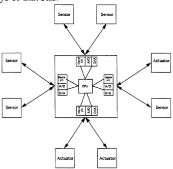
The traditional design of a mobile autonomous robot revolves around a single central control unit (CCU) that has a central processing unit (CPU) to perform all the sensor fusion, mapping, and planning functions. The CCU normally possesses multiple digital and analog I/O pins. This was the architecture used in the design of the Unmanned Vehicle Lab's MITy
prototype series. As Figure 4-1 demonstrates, the architecture resembled a star formation where the CCU is the center of the star and the various sensors and actuators are the rays of that star.
Figure 4-1. Traditional Centralized Processing Architecture
Each transducer is wired directly back to the CCU's I/O pins. As previously mentioned (see Section 2.2), the MITy series used a Zilog Little Giant board as its CCU board. This board possessed a Z180 microprocessor and multiple digital and analog I/O ports. The support and signal conditioning circuitry necessary to allow for more efficient data transmission and easier interfacing
Chapter 4: Traditional Centralized Control Networks
between the transducers' I/O and the CPU's I/O was placed out at the transducers.
There are a number of advantages and disadvantages to this archi-tecture. The use of a single CCU board was an inexpensive alternative to having multiple control units. Also, since the hardware and low-level software were geared mainly toward interfacing the transducers to the CCU, the design was fairly straightforward and uncomplicated. Another advantage was that since each transducer was a separate ray of the star, a transducer failure would not cause a catastrophic failure to the electrical system.
However, in many regards the disadvantages outweigh the advantages. The direct wired architecture of the MITy series was inflexible and consequently not very modular or expandable.
For example, an acoustic range finder used for hazard avoidance may require a power rail of 5V, two digital I/O lines and possibly some sophis-ticated signal conditioning circuitry. If a decision was made to upgrade the hazard avoidance sensor to the laser range finder found on MITy-2, then a power rail of 12V would have to be run in addition to the 5V rail, another digital I/O line would have to run, and the signal conditioning circuitry would definitely change. All of these changes can create a logistics nightmare for the layout of the electrical system. First, all the digital I/O lines may
already be committed. This means that circuitry must be designed or bought to extend the digital I/O of the CCU. Second, since there may be no space left on the connectors that interconnect the various components of the robot, mechanical alterations to the robot's frame may become necessary to accommodate more connectors. These mechanical changes may require subsequent changes to the electrical system. This domino affect ends up wasting time and resources and usually brings R&D efforts to a stand still.
The low-level software used to control the sensor must be completely
rewritten as well since the software-hardware interface for the sonar and laser is completely different. Altering the low-level software may also require changes in the robot's higher-level control code and now software begins experiencing the same problems that were experienced in hardware.
Another drawback of the MITy series architecture was the inability to carry out parallel development of transducers. The only way to achieve parallel development was by completely laying out the robot in advance. This task included: delegating I/O resources to all the transducers;
determining the size, shape, and configuration of each transducer on the robot; and routing the necessary power lines to each transducer. Once the robot's layout was finalized, it became difficult to implement any changes.
The limitations experienced with the MITy series permeate all robot designs that utilize a direct-wired transducer platform. The time and the cost necessary to change the layout of the system make this architecture non-versatile and extremely inefficient. The inability to easily upgrade the transducers on the robot guarantees that the system will quickly become obsolete.
4.2. MITe Prototype Series: A Bus-based Transducer Platform:
The MITe series was an attempt to improve upon the MITy
architecture. Though the MITes still utilized a single CCU to assimilate the sensor data and to carryout all the higher level control code, a bus-based architecture was introduced to minimize the disadvantages experienced by the MITy series. The signal conditioning circuitry and interface electronics for each transducer were built onto circuit cards that plug into the robot's 8-bit data bus. The MITe possessed eight expansion slots that were accessible by a 3-bit address bus. This allowed access to a minimum of eight different
Chapter 4: Traditional Centralized Control Networks
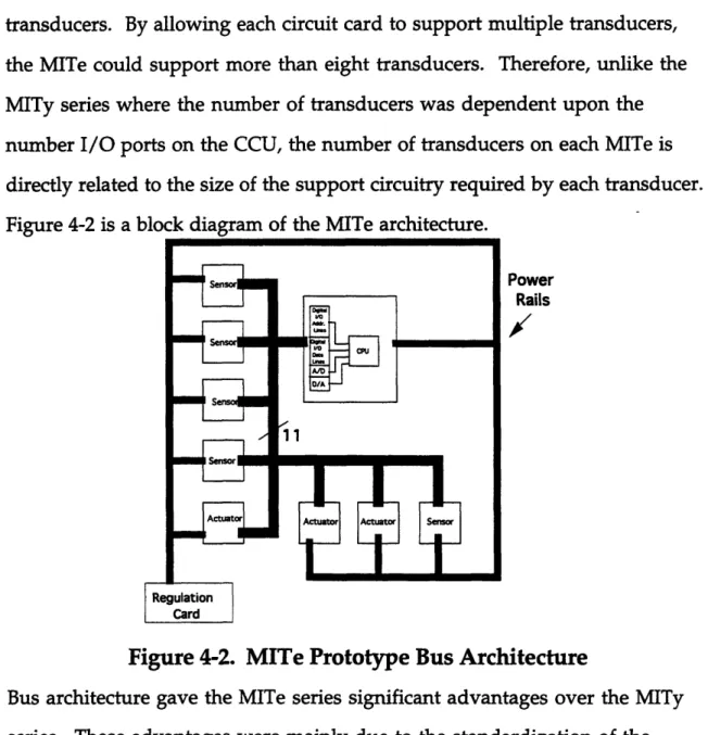
transducers. By allowing each circuit card to support multiple transducers, the MITe could support more than eight transducers. Therefore, unlike the
MITy series where the number of transducers was dependent upon the number I/O ports on the CCU, the number of transducers on each MITe is
directly related to the size of the support circuitry required by each transducer. Figure 4-2 is a block diagram of the MITe architecture.
Power Rails
/
Figure 4-2. MITe Prototype Bus Architecture
Bus architecture gave the MITe series significant advantages over the MITy series. These advantages were mainly due to the standardization of the hardware interface guaranteed by the bus. Each transducer has access to the same digital and analog I/O lines and all the voltage rails. This made the robot's hardware easier to maintain, re-task, and upgrade. It also permitted parallel development and off-line testing of transducer circuitry. However, the bus-based architecture did have some disadvantages that the traditional direct-wired system did not. The bandwidth of the bus was a major limiting factor on how often the transducers could be accessed by the CPU. Also, timing issues became very important to guarantee that the correct
information was being accessed at any one time. Though the hardware saw improvements due to the standardized bus, the hardware-software interface had become extremely complex to deal with the transmission of data across the bus. The bus architecture was also susceptible to catastrophic failure due to a transducer failure. For example, if a transducer's bus-card shorted two of its digital bus lines to ground, then the bus would be corrupted making it impossible access any of the other transducers. Like the MITy series, the MITes could suffer from a catastrophic microprocessor failure as well as the fact that the CPU was still loaded down by sensor fusion.
4.3. Companion Prototype:
As previously mentioned (see section 2.4), the removal of the size constraints that had been imposed upon the planetary micro-rover and the
inundation of a substantial amount of IR&D funding allowed for the design of a far more sophisticated robot than the MITy or MITe series. Using the knowledge gained through testing the MITy prototypes, it was determined that the Companion should possess some form of distributed processing. The use of multiple processors would alleviate the problems normally associated with trying to carryout sensor fusion and path planning on the same CPU. As Figure 4-3 shows, the Companion prototype had many of the same attributes as the MITy and MITe prototypes.
Chapter 4: Traditional Centralized Control Networks
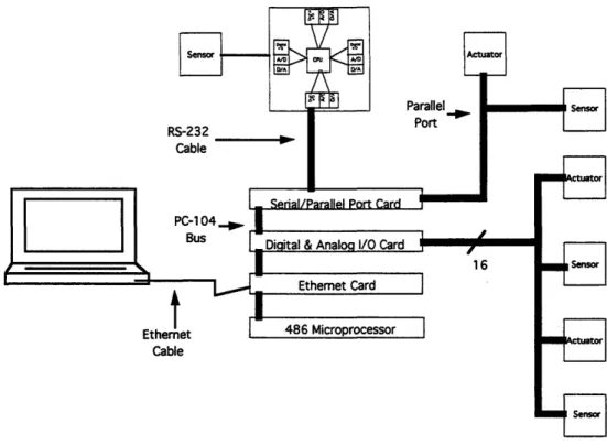
Figure 4-3. Companion Multiple Processor Architecture
Companion's control system was divided between the processing of the sensors' data and the path planning that was carried out after the data had been assimilated. All the sensor fusion occurred on the 486 microprocessor board. This board used a PC-104 bus interface. This allowed for additional peripheral boards to be stacked onto the microprocessor card. Purchasing off-the-shelf computer cards gave an added benefit since software drivers were normally included to handle the interface between the processor and its resources. With the MITe architecture, a custom interface had to be designed to allow the processor to access all the transducers. The commercially
supplied drivers greatly simplified the development time for the hardware-software interface on Companion. Figure 4-3 only shows the more common peripheral cards that were used with the Companion prototype. The PC-104 based microprocessor board communicated to a 486 laptop via an ethernet cable. The higher level control code was performed on the laptop. Though full assimilation of sensor data was necessary for control, the utilization of
multiple CPUs allowed for more efficient processing. As with the previous prototype series, the hardware signal conditioning occurred out at the transducers. The transducers were interfaced to the PC-104 microprocessor board via the I/O bus provided by the Digital and Analog I/O card. As with the MITy architecture, parallel development of both hardware and software was only possible after the I/O resources had been delegated for each
transducer. However, since more than one I/O card can be placed on the PC-104 stack, the robot's transducer suite can easily be expanded. This expansion was limited only by the number of peripheral cards that the microprocessor can support. As additional cards were added to provide GPS and ethernet capabilities, this limitation became a concern. One method to deal with this limitation was to add an additional microprocessor to deal with new
transducers. A Zilog Little Giant board was connected to the PC-104 based 486 board via a RS-232 line. The Little Giant was then used to interface a gyro into the Companion's navigation system. This was UVL's first
implementation of a smart sensor (see Chapter 5).
Though using commercially available components allowed for a more robust and sophisticated robot, their cost was much higher than the circuits
designed by the UVL graduate students. Also, as with the MITy and MITe series, the robot could still suffer a catastrophic processor failure. If either the PC-104 based 486 board or the laptop suffered a failure, the robot would be unable to recover. The ability to upgrade was limited by the fact that new transducers required a re-distribution of I/O resources. Not surprisingly, the fact that most of the electronics were bought commercially and not designed in-house led to a limited understanding of the overall hardware system. Consequently, this made the robot harder to maintain and debug.
Chapter 4: Traditional Centralized Control Networks
4.4. Summary of Advantages/Disadvantages of UVL Systems:
As demonstrated above, all the UVL systems have their own
advantages and disadvantages. All share common problems extending from the areas of sensor fusion, catastrophic processor failures, and limited
modularity/upgradability. It was important to summarize these points to allow for a better understanding of the benefits of the proposed smart sensor system. The following list gives a breakdown of the various UVL systems:
Direct Wired Transducer Platform (MITy Series): * Single CPU for all transducer processing
* Hardware signal conditioning carried out at transducer * Transducers directly wired to I/O pins on CPU board * Full assimilation of sensor data necessary for control
Bus Based Transducer Platform (MITe Series):
* Single CPU for all transducer processing
* Hardware signal conditioning carried out at transducer * Transducer circuitry built on cards that plug into I/O bus of
CPU
* Full assimilation of sensor data necessary for control Hierarchical Control Architecture with Multiple Processors (Companion):
* Independent CPU used for all Sensor Fusion
* Independent CPU used for Path Planning and Mapping * Hardware signal conditioning carried out at transducers * Sensor Fusion CPU and Planner CPU connected via ethernet * Full assimilation of sensor data necessary for control;
however, multiple CPU's allow for more efficient processing * Independent CPU used for processing of Gyro information
Table 4-1. UVL System Breakdown
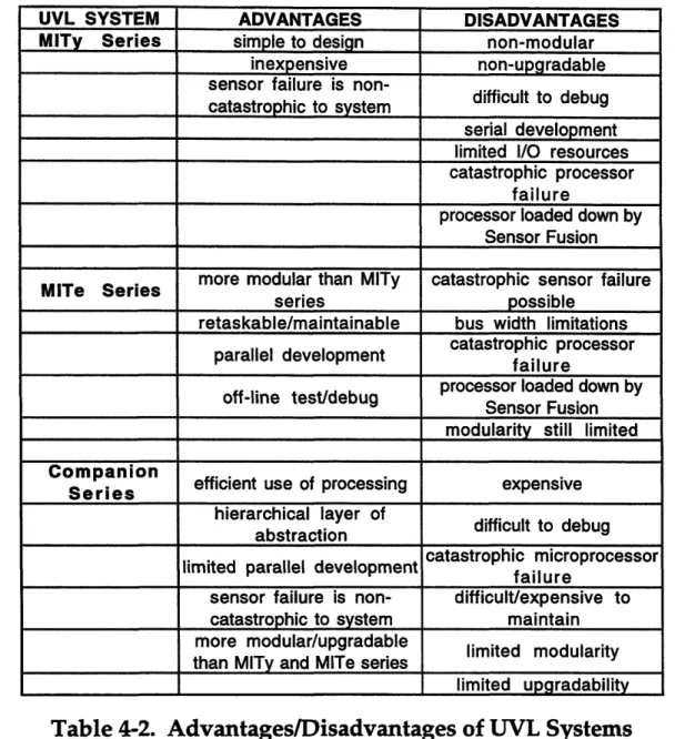
Table 4-1 gives a summary of the advantages and disadvantages of each system.
UVL SYSTEM ADVANTAGES DISADVANTAGES MITy Series simple to design non-modular
inexpensive non-upgradable sensor failure is
non-ic to stem difficult to debug
catastrophic to system
serial development limited I/O resources catastrophic processor
failure
processor loaded down by Sensor Fusion more modular than MITy catastrophic sensor failure
MITe Series
series possible
retaskable/maintainable bus width limitations catastrophic processor parallel development failure
failure
processor loaded down by off-line test/debug Sensor Fusion
modularity still limited
Companion
Serieos efficient use of processing expensive hierarchical layer of
difficult to debug
abstraction
catastrophic microprocessor
limited parallel development failure
sensor failure is non- difficult/expensive to catastrophic to system maintain more modular/upgradable limited modularity than MITy and MITe series
limited upgradability
Table 4-2. Advantages/Disadvantages of UVL Systems
As can be seen from Table 4-1, the disadvantages outweigh the advantages of each system. The greatest concern revolves around the difficulty of
upgrading the robot's sensor and actuator suite. These limitations make the robots hard to maintain and therefore hard to market to perspective buyers. The need to design a more efficient and maintainable robot led to the UVL's initial research into the area of smart sensor technology.
Chapter 5: Smart Modules
SMART MODULES
CHAPTER 5
5.1. Overview of Smart Sensors:
After analyzing the list of the advantages and disadvantages of the
UVL systems (see Section 4.4), it was concluded that a more robust and
efficient system could be designed if it possessed the following attributes:
* distributed processing to allow for better assimilation of sensor data,
* a predefined hardware interface that would allow for parallel development of transducers,
* transducers should be connected by a data bus that would allow for easier modularity and upgradability, * transducers should have plug-and-play capabilities to
increase system testability and maintainability, * the failure of any one transducer should not cause a
catastrophic system failure,
* and the overall system should be simple and inexpensive to design.
It was already known that the robot's control architecture closely resembled the control systems implemented in test and measurement applications. A central controller normally directs the actions of instruments, sensors, and actuators; polls for any results; and manages the resulting data.[6] This
knowledge led to research into how other applications, that utilized a similar control architecture as the robots, dealt with the drawbacks of traditional direct-wired centralized control. It was found that the instrumentation and control system industry had determined that the use of specialized sensor buses was the necessary solution to obtain a more efficient, low cost, high quality product.[7] The idea behind these sensor buses was to turn the
traditional control system architecture into a network where the transducers act as nodes.
Accordingly, the nodes need a certain amount of intelligence to allow interface with the sensor network. Nader Najafi of MRL/Sensors coined the term 'smart sensor'. Najafi determined that a smart sensor should: possess all analog and digital signal processing; digitize analog transducer outputs; have a bi-directional bus for communication; contain a specific network address to allow user access and identification; and be able to receive and execute commands over a digital bus.[8] John Eidson and Stan Woods, both of Hewlett-Packard, designed a research prototype of a networked smart sensor system. They defined the hardware design of a smart sensor as including:
* a communication transceiver module for connection to the physical communication medium,
* a common core module that will configure the node, convert transducer signals to digital data with standard units, and manage the flow of data into and out of the node,
* and a transducer interface module that signal conditions the transducer output.
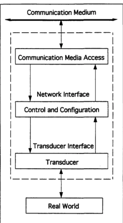
This hardware design has become the industry standard for a smart sensor.[6] As Figure 5-1 shows, the three major blocks of the smart sensor
architecture are the Communication Media Access block, the Control and Configuration block, and the Transducer block.
Chapter 5: Smart Modules
Figure 5-1. Smart Node Architecture
The Communication Media Access block is responsible for handling the low-level protocol between the node and the physical medium. For many of the sensor networks on the market, this block is designed around a
media-dependent transceiver. The Control and Configuration block acts as the data path between the application interface with the transducer and commu-nication interface with the physical media. Unlike the Commucommu-nication Media Access block, this data path, which is illustrated in Figure 5-2, is identical in all smart sensors.
Figure 5-2. Data Path
The importance of the Control and Configuration block lies in the fact that it is responsible for converting the transducer's output to a usable format. The Physical Transformation converts between the digital representation in SI units and the transducer's raw digitized data. The Application Transfor-mation converts between the SI unit representation and the application representation that appears on the network.[6] The application
trans-formation can be as sophisticated as the designer wants; however, even when performing the simplest application transformations, the smart node
eliminates much of the processing load normally placed on the central controller due to data digitization, filtering, and signal processing.
Tom Ormond, Senior Technical Editor of EDN, confirms that a smart sensor should consist of a transducer combined with signal conditioning and other circuitry to produce data signals that have been logically operated upon to increase their value of information.[8] Ormond hypothesizes that the
Sensor Actuator Nodes Nodes Sensor Nodes Actuator Nodes
Chapter 5: Smart Modules
simplest smart sensor is composed of a transducer with signal conditioning circuitry to filter and scale the output. Using this definition, the transducers implemented on the UVL prototypes can be considered smart sensors. However, as was shown by the earlier research of the UVL, an efficient and cost-effective control system can not be designed using this basic model of a smart sensor. A higher and more effective level of sensor intelligence can be achieved by adding communication capabilities. This includes the addition of A/D and D/A converters at the sensor and actuator nodes respectively, as well as the addition of transducer addressability to allow user access of individual nodes. These features allow for the use of a bi-directional digital bus to interconnect the various transducer nodes and the central controller. Consequently, the computational load on the central control processor will be lessened since the incoming data will be in a predefined digital format.
By placing a microcontroller at the sensor or actuator, a more effective and useful node can be achieved. Varying levels of intelligence can be
attained by simply altering the code running on the microcontroller. At the simplest level, the microcontroller can be programmed to carryout all the necessary computations to turn the transducer's raw data into SI units. The microcontroller can also be programmed to monitor the output of the sensor and only transmit the data to the central controller after certain criteria have been met. For example, constantly transmitting the output of a gyro node being used for navigation would be an ineffective use of the network's
bandwidth. Instead, the node can be programmed to sample the gyro's output and only transmit data to the central controller periodically. Alternately, more advanced code could be run on the node's microcontroller to transmit the gyro's data only when a significant enough change has occurred to
designate an actual course change. By programming all the nodes in this manner, the control architecture can make the best use of the bus' bandwidth.
There are a number of properties that should be met when designing a smart sensor system. As shown in Table 5-1, Eidson and Woods divide these properties into transducer-related, measurement-related, and application-related properties.[6]
Transducer-Related Measurement-Related Application-Relate Changing measurement Physical variable Timing management properties by accepting
network messages
I/O format Data management Communication Pattern Computational Managing
Calibration characteristic communication characteristic
properties
Ident ity Identity Synchronizing node
clocks
Operational ranges Location Control Models
Table 5-1. Smart Node Properties
It must be understood that for a node to possess these properties it must have a microcontroller. Most of these properties are dependent upon the code running on the microcontroller. Many of the smart sensor networking tools on the market have prewritten protocols that deal with the time
management, I/O format and network communication properties. The physical variable: distance, temperature, etc., identity, calibration, and operational ranges are all properties provided by the application program written by the user. By adhering to these design rules, a group of smart nodes can be created and connected into a control system that far exceeds the control
architecture on the various UVL prototypes.
5.2. Smart Modules
--
A Flexible Control Architecture:
As mentioned above, the reason that UVL began researching the area of smart sensors was to find a system that did not suffer from the same