HAL Id: hal-00296808
https://hal.archives-ouvertes.fr/hal-00296808
Submitted on 9 Aug 2005
HAL is a multi-disciplinary open access
archive for the deposit and dissemination of
sci-entific research documents, whether they are
pub-lished or not. The documents may come from
teaching and research institutions in France or
abroad, or from public or private research centers.
L’archive ouverte pluridisciplinaire HAL, est
destinée au dépôt et à la diffusion de documents
scientifiques de niveau recherche, publiés ou non,
émanant des établissements d’enseignement et de
recherche français ou étrangers, des laboratoires
publics ou privés.
OpenMI: the essential concepts and their implications
for legacy software
J. B. Gregersen, P. J. A. Gijsbers, S. J. P. Westen, M. Blind
To cite this version:
J. B. Gregersen, P. J. A. Gijsbers, S. J. P. Westen, M. Blind. OpenMI: the essential concepts and
their implications for legacy software. Advances in Geosciences, European Geosciences Union, 2005,
4, pp.37-44. �hal-00296808�
Advances in Geosciences, 4, 37–44, 2005 SRef-ID: 1680-7359/adgeo/2005-4-37 European Geosciences Union
© 2005 Author(s). This work is licensed under a Creative Commons License.
Advances in
Geosciences
OpenMI: the essential concepts and their implications for legacy
software
J. B. Gregersen1, P. J. A. Gijsbers2, S. J. P. Westen3, and M. Blind4
1DHI – Water & Environment, Agern All´e 5, 2970 Hørsholm, Denmark 2WL/Delft Hydraulics, P.O. Box 177, 2600 MH Delft, The Netherlands
3WSL – Wallingford Software Ltd, Howbery Park, Wallingford, OX10 8BA, UK
4RIZA Institute for Inland Water Management and Waste Water Treatment, P.O. Box 17, 8200 AA Lelystad, The Netherlands
Received: 1 August 2004 – Revised: 1 November 2004 – Accepted: 15 November 2004 – Published: 9 August 2005
Abstract. Information & Communication Technology (ICT) tools such as computational models are very helpful in de-signing river basin management plans (rbmp-s). However, in the scientific world there is consensus that a single inte-grated modelling system to support e.g. the implementation of the Water Framework Directive cannot be developed and that integrated systems need to be very much tailored to the local situation. As a consequence there is an urgent need to increase the flexibility of modelling systems, such that dedi-cated model systems can be developed from available build-ing blocks. The HarmonIT project aims at precisely that. Its objective is to develop and implement a standard inter-face for modelling components and other relevant tools: The Open Modelling Interface (OpenMI) standard. The OpenMI standard has been completed and documented. It relies en-tirely on the “pull” principle, where data are pulled by one model from the previous model in the chain. This paper gives an overview of the OpenMI standard, explains the foremost concepts and the rational behind it.
1 Introduction
The concept of integrated catchment management has arisen because managing environmental processes independently does not always produce sensible decisions when the wider view is taken. Therefore, it becomes important to be able to model not only the individual catchment processes such as ground water, river flow, irrigation, etc, but also their in-teractions. However, most existing models tend to address only single issues. The objectives of the HarmonIT project address these problems through the development of an open modelling interface (OpenMI) that will facilitate easy linking of existing and new models, promoting collaboration and use of external (OpenMI-compliant) software.
Correspondence to: J. B. Gregersen
Within the HarmonIT project about 20 legacy models will be migrated to the OpenMI platform. Since the standard should survive the project, much effort is put into the post-project organisation of maintaining the standard. As a con-sequence we believe that the number of OpenMI compliant models will keep growing beyond the timeframe of the Har-monIT project.
Most existing hydrological decision support systems use combined hydrological models as one of the main building blocks. Creation of such systems has so far been prerogative to the model suppliers. Now with OpenMI compliant models available also third parties can create such systems for their specific needs.
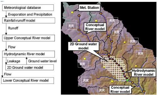
In order to demonstrate the capabilities of OpenMI a com-plex system of integrated catchment modelling is shown on Fig. 1. Meteorological data from a number of measurement stations are handled by a database system. This system will provide precipitation and evaporation data to rainfall-runoff models. The rivers are modelled by a simple conceptual river model that will obtain inflow data from the rainfall-runoff models. For a particular river reach a more detailed represen-tation of the river flow is required. This river reach is mod-elled by a physically based hydrodynamic river model. The river model will obtain inflow data for its upper boundary from the conceptual river model and will provide inflow data for the conceptual river models that connects to the down-stream boundary of the hydrodynamic river model. Interac-tion between ground water and surface water is considered important at the location of the hydrodynamic model. The underlying aquifer is modelled by a 2-D distributed ground water model. The ground water model will receive leakage from the river model. The river model will calculate this leakage based on information about the ground water level, which is obtained from the ground water model.
38 J. B. Gregersen et al.: OpenMI: the essential concepts and their implications for legacy software
Fig. 1. Example of integrated catchment modelling that can be realised by combining OpenMI compliant models.
Fig. 2. Model application pattern.
A model user that has access to OpenMI compliant models needed for this particular system can establish such a system. The procedure the user needs to follow in order to establish such systems is:
1. The user will populate each of the models with the re-quired data through the preparatory user interfaces of each individual model.
2. The user will use an OpenMI configuration editor to query each model for providing data and accepting data and subsequently establish links between the models. 3. The user will run the linked system.
4. The user will investigate the results from the calcula-tions through the preparatory user interfaces of each in-dividual model.
The steps above are especially valid for complex legacy software. We foresee that in time new models will be de-veloped with OpenMI compliant user interfaces, and that in time more and more “generic” OpenMI compliant post-processing tools will become available.
2 Existing Model Systems
Before going into detail about OpenMI some definitions of the existing model systems are given.
A model application is the entire model software system that you install on your computer. Normally a model appli-cation consists of a user interface and an engine. The engine is where the calculations take place. The user supplies infor-mation through the user interface upon which the user inter-face generates input files for the engine. The user can run the model simulation e.g. by pressing a button in the user inter-face, which will deploy the engine (see Fig. 2). The engine will read the input files, perform calculations and finally the results are written to output files. When an engine has read its input files it becomes a model. In other words a model is an engine populated with data. A model can simulate the behaviour of a specific physical entity e.g. the River Rhine. If an engine can be instantiated separately and has a well-defined interface it becomes an engine component. An en-gine component populated with data is a model component. There are many variations of the model application pattern described above, but most important from the OpenMI per-spective is the distinction between model application, engine, model, engine component, and model component.
J. B. Gregersen et al.: OpenMI: the essential concepts and their implications for legacy software 39
3 OpenMI
3.1 LinkableComponent
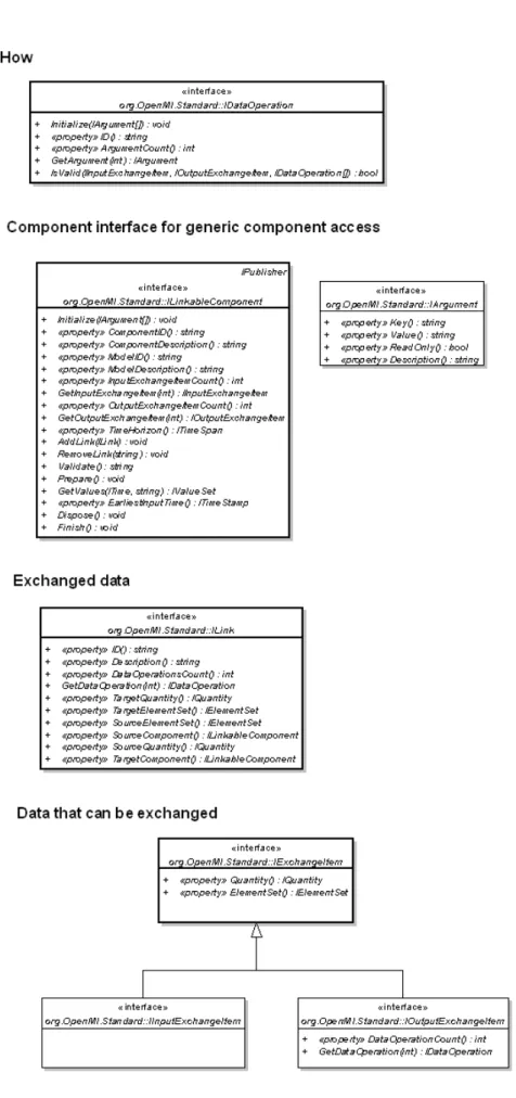
Basically, a model can be regarded as an entity that can provide data and/or accept data. Most models receive data by reading input files and provide data by writing output files. However, the approach for OpenMI is to access the model directly at run time and not to use files for data ex-change. In order to make this possible, the engine needs to be turned into an engine component and the engine component needs to implement an interface through which the data in-side the component is accessible. OpenMI defines a standard interface for engine components (ILinkableComponent, see Fig. 3) that OpenMI compliant engine components must im-plement. When an engine component implements the ILink-ableComponent interface it becomes an OpenMI Linkable-Component.
3.2 Link (what is exchanged)
One LinkableComponent can retrieve data from another LinkableComponent by invocation of the GetValues method. However, this is only possible if the two components have information about each other’s existence and have a clear definition of the kind of data that is requested. This infor-mation is contained in a class that implements the OpenMI ILink interface. Before invocation of the GetValues method a Link object must be created, populated and added to the two components by use of the AddLink method.
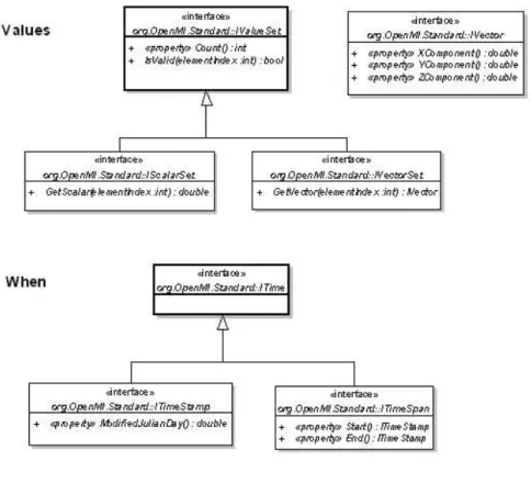
The Link object holds a reference (handle) to the two linked components. The Link object also contains informa-tion about what is requested, where the requested values ap-ply, and how the requested data should be calculated. This information is included in the OpenMI Quantity class, the OpenMI ElementSet class, and the OpenMI DataOperation class, respectively. (see the ILink interface on Fig. 3 and 4). 3.3 Quantity (what)
The Quantity object defines what should be retrieved. This could be e.g. water level or flow. The Quantity class repre-sents this information simply as a text string (the Description property). OpenMI does not provide any naming convention for quantities. The Link class has a target Quantity object and a source Quantity object. The quantity description in the source Quantity object must be recognizable by the source LinkableComponent and the quantity description in the tar-get Quantity object must be recognizable by the tartar-get Link-ableComponent. It is the responsibility of the person that configures the linked system to ensure that the combination of the two particular quantities makes sense physically. 3.4 ElementSet (where)
The ElementSet object defines where the retrieved values must apply. A ground water model may be requested for ei-ther the ground water level at a particular point or the ground
water level as an average value over a polygon. A river model may be requested for the flow at a particular calcu-lation node. These locations are defined in the ElementSet. The ElementSet is a collection of Elements, where each el-ement can be an ID-based entity like a particular node or a geometrical entity. A geometrical entity is either a point, a polyline, a polygon, or a 3-D shape. The GetValues method returns a ValueSet, which is an array of values or an array of vectors. Each value in the returned ValueSet applies to one Element in the target ElementSet.
3.5 DataOperation (how)
The DataOperation object defines how the requested values should be calculated. Examples of data operations could be time accumulated, spatially averaged, maximum values etc. There are
no OpenMI conventions for data operations. As for the quantities, the data operations are simply defined by a text string, which is recognizable by the source LinkableCompo-nent.
The Link class defines a specific connection between two LinkableComponents. For two specific LinkableCompo-nents many possible links may exist.
3.6 ExchangeItem (what can be exchanged)
When model links are created and populated, information about which quantities, locations and operations each Link-ableComponent will support is needed. This information can be obtained by querying the LinkableComponents for InputExchangeItems and the OutputExchangeItems. Each InputExchangeItem contains a Quantity and an ElementSet describing what can be accepted at which location. Each OutputExchangeItem contains a Quantity and an ElementSet describing what can be provided at which location. Out-putExchangeItems also contains information about available DataOperations. OpenMI configuration editors will typically query the ILinkableComponent interfaces in order to display potential input and output exchange items to the user for each model in a configuration. This will enable the user to select the desired connections (Links).
3.7 Time
Time in OpenMI is defined either by a TimeStamp interface or a TimeSpan interface, both interfaces inherited from the OpenMI Time interface. A time stamp is a single point in time whereas the time span is a period from a begin time to end time. Each of these times is represented by the Modified Julian Date. A modified Julian date is the Julian date minus 2400000.5. A modified Julian date represents the number of days since midnight 17 November 1858 Universal Time on the Julian calendar.
40 J. B. Gregersen et al.: OpenMI: the essential concepts and their implications for legacy software
J. B. Gregersen et al.: OpenMI: the essential concepts and their implications for legacy software 41
42 J. B. Gregersen et al.: OpenMI: the essential concepts and their implications for legacy software
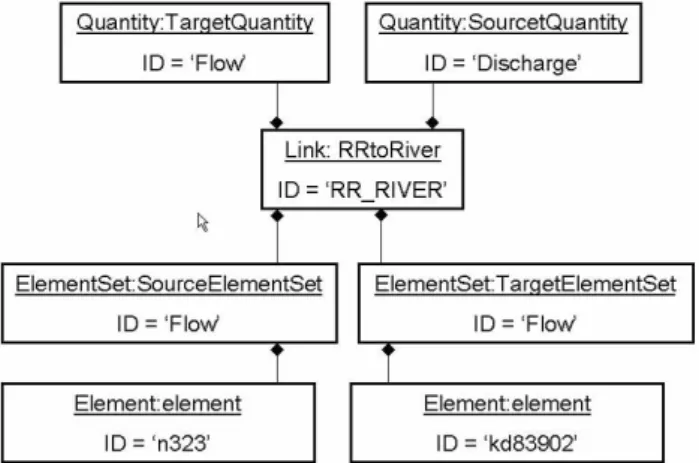
Fig. 5. The populated Link class.
3.8 GetValues
Now let us move back to the essence of OpenMI, the GetVal-ues method. When one LinkableComponent invokes the Get-Values method of another LinkableComponent, the source LinkableComponent must return the values for the specified quantity, the specified time stamp or time span, and at the specified location. If the LinkableComponent is of the time stepping kind of numerical model it will do no calculation until it receives a GetValues call. Once the GetValues method is invoked, it will calculate as long as it is necessary to obtain the needed data. Usually it will be necessary for the source component to interpolate or extrapolate its internal data in time and space before these can be returned.
The OpenMI architecture puts a lot of responsibilities on the LinkableComponents. One of the reasons for this is that we feel that any data conversion like interpolations can be done in the most optimal way by the source component. If the source component is e.g. a ground water model any inter-polations of the ground water levels are most safely done by the ground water model itself rather than some external tool. The OpenMI framework is very simple or you may say that there is no framework. All there is, is LinkableCompo-nents. Once the system of linked model components is cre-ated, the invocation of GetValues methods from one model component to another is driving the calculations. Since the ILinkableComponent interface (Fig. 3 and 4) does not have any methods that can be used to start the chain of calcula-tions, a trigger component is needed. The trigger component is a Linkable component that has an additional method for starting calculations (see example below).
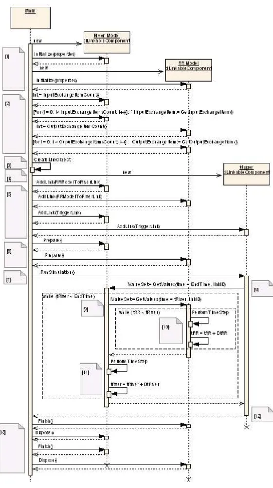
4 Example
Let us look at a very simple example: A conceptual lumped rainfall runoff (RR) model provides inflow to a river model. The populated link class is shown in Fig. 5.
The sequence diagram in Fig. 6 shows the calling sequence for a configuration with a river model linked to a
rainfall-runoff model. The diagram demonstrates how things would look if a “hard-coded” configuration was used. For normal usage of OpenMI a configuration editor would assist you in creating the configuration.
The sequence diagram has the following steps:
1. The River Model object and the RR Model object are instantiated. Then the Initialize method is invoked for both objects. Models will typically read their private input files when the Initialize methods is invoked. In-formation about name and location of the input files can be passed as arguments in the Initialize method. 2. The River model is queried for InputExchangeItems
and the RR model is queried for ems. The InputExchangeItems and OutputExchangeIt-ems objects contain information about which combina-tions of Quantities and ElementSets (locacombina-tions) can be accepted by the components as input or output, respec-tively.
3. A Link object is created and populated based on the obtained lists of InputExchangeItems and OutputEx-changeItems. In this example we are using a hard-coded configuration. However, if a configuration edi-tor was used the OutputExchangeItem and the InputEx-changeItems would be selected by the user using e.g. a selection box.
4. The trigger component is created. This component is a very simple LinkableComponent whose only purpose is to trigger the calculation chain.
5. Link objects are added to the LinkableComponents. This will enable the LinkableComponents to invoke the GetValues method in the LinkableComponent to which they are linked to.
6. The Prepare method is invoked in all LinkableCom-ponents. This will make each LinkableComponent do whatever preparations are needed before calculations can start.
7. Invoking the RunSimulation method in the trigger ob-ject starts the calculation chain.
8. The trigger object invokes the GetValues method in the River Model and the River model will calculate until it has reached the EndTime specified in the argument list. 9. Before the River Model can make a time step it must update its inflow boundary condition. In order to do this the GetValues method in the RR model is invoked. 10. The RR model will repeatedly perform time steps until
it has reached or exceeded the time for which it was re-quested for values. If the River Model and the RR model are not synchronous with respect to time stepping, the RR Model must interpolate the calculated runoff in time before the values can be returned.
J. B. Gregersen et al.: OpenMI: the essential concepts and their implications for legacy software 43
44 J. B. Gregersen et al.: OpenMI: the essential concepts and their implications for legacy software
Fig. 7. Model engine wrapping design pattern.
11. The River model has now obtained its inflow boundary value and can perform a time step. The River Model will repeatedly invoke the GetValues method in the RR model and perform time steps until it has reached or exceeded the EndTime, where after it will return control and values to the trigger object.
12. The trigger object returns control to the main program. 13. The main program will invoke the Finish and the
Dis-pose method in all LinkableComponents. Linkable-Components will typically close output files when the Finish method is invoked. The Dispose method will typically be used by the LinkableComponents to de-allocate memory.
5 OpenMI utility and tools
At first hand it may seem like a huge challenge to turn a model engine into an OpenMI compliant LinkableCompo-nent. However, it is not so difficult. OpenMI provides guide-lines for migration of models and a great number of software tools and utilities that will make migration easier [1]. These tools and utilities can be used by anyone who is migrating a model but are not required in order to comply with the OpenMI standard. The implemented utilities and tools are available as open source in a C# and Java version (OpenMI, 2005).
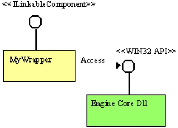
For existing model engines wrapping is the recommended technology. If a model engine is e.g. a numerical model pro-grammed in Fortran this engine can be compiled into a dy-namic link library (dll). This dll can then be accessed from a wrapper class that implements the ILinkableComponent in-terface (see Fig. 7).
Model engines that are doing time step based computa-tions have many thing in common. It was therefor possible to develop a generic wrapper that can be used for these en-gines. This wrapper provides a default implementation of the ILinkableComponent interface. The generic wrapper class will take care of all the bookkeeping associated with han-dling links, all event and exception hanhan-dling and (basically) all the interpolation in time and space. We estimate that mi-gration of models will take between a few weeks to a few months of work, depending on how well organized the origi-nal program code is.
OpenMI also provides software class libraries for build-ing configurations editors, advanced control features like it-eration and optimization controllers and many other multi-purpose tools for visualising results, assessing performance etc.
6 Conclusions
The OpenMI standard and associated tools and utilities will be an attractive means for model providers and model users to create systems for integrated catchment management. One of the major benefits is that once a model has been migrated to OpenMI it can be used in a large number of different com-binations with other OpenMI compliant models. However, this is only true if there is a significant number of compliant models available and if the OpenMI standard and associated tools are supported in the future.
The commercial partners of the HarmonIT project, DHI – Water & Environment, WL – Delft Hydraulics, and WSL – Wallingford Software Ltd are currently working on commer-cial releases of OpenMI compliant versions of some of the most widely used hydraulic and hydrological model systems. Also the non-commercial HarmonIT partners and universi-ties around the World will make OpenMI compliant models available.
An OpenMI consortium will be established and will have the task of maintaining and supporting the OpenMI standard and associated tools. The standard, utilities, guidelines and documentation will be freely available to the public.
More information about OpenMI and HarmonIT is provided on our web site http://www.OpenMI.org.
Edited by: P. Krause, S. Kralisch, and W. Fl¨ugel Reviewed by: anonymous referees
References