A Dynamic Model of the Extravehicular Mobility Unit (EMU):
Human Performance Issues During EVA
by
David B. Rahn
S.B. Aeronautics and Astronautics Massachusetts Institute of Technology, 1995
Submitted to the Department of Aeronautics and Astronautics in partial fulfillment of the requirements for the degree of
Master of Science in Aeronautics and Astronautics
at the
Massachusetts Institute of Technology
June 1997
Copyright @ 1997 Massachusetts Institute of Technology. All rights reserved.
Signature of Author...
--- lpartment oTWeronautics and Astronautics May 23, 1997
Certified by ...
,,n Professor Dava J. Newman
4
j A Thesis Supervisor A ccepted by ...Professor Jaime Peraire .. _,;-;'.sE_ ; . .Chairman, Department Graduate Committee
OF IL~-~i :1EI
JUN
1
9
19971
A Dynamic Model of the Extravehicular Mobility Unit (EMU):
Human Performance Issues During EVA
by David B. Rahn
Submitted to the Department of Aeronautics and Astronautics on May 23, 1997 in partial fulfillment of the
requirements for the Degree of Master of Science in Aeronautics and Astronautics
Abstract
A dynamic model of the extravehicular mobility unit (EMU) space suit was developed and applied to the simulation of several extravehicular activity (EVA) tasks. The space suit model was created from mass, inertia, and torque data to augment the unsuited 12-segment human model used in previous studies. A modified Preisach model was introduced to describe the hysteretic torque characteristics of joints in a pressurized space suit, and implemented numerically based on observed suit parameters. Four computational simulations were then performed to observe the effect of suit constraints on simulated astronaut performance, involving manipulation of the Spartan astrophysics payload on STS-63. It was found that the shoulder joint work required for a suited EVA crewmember to move the Spartan payload while in an inefficient posture was a full order of magnitude greater than the unsuited condition. Moving to a posture more accommodating to the suit's neutral position, the simulated astronaut completed the task with an actual decrease in shoulder work from the unsuited condition; to compensate for reduced upper-body mobility, however, the ankle joint was forced to use its long lever arm to manipulate the payload, resulting in ankle work 207% greater than in the unsuited condition. In this situation, muscle fatigue would set in more quickly than expected, a problem for the long-duration EVA missions expected on the International Space Station. The Spartan results agree with anecdotal evidence of post-EVA ankle fatigue, and demonstrate the
effectiveness of both the space suit model and the simulation technique.
Thesis Supervisor: Dava J. Newman
Acknowledgments
Funding and resources for this work were provided by NASA Grant NAGW-4336 and the MIT Man-Vehicle Lab.
I cannot begin this page without thanking Professor Dava Newman from the bottom of my heart for wonderful advice and friendship; I don't think I would have survived without your guidance and support over the last three years. You've seen my transition from a bright-eyed UROP to a more ... refined persona, watching in amazement, I'm sure. Our
conversations have done more to shape my future than you might think! It has been a pleasure working with you, and I'm sure our paths will cross in the not-so-distant future. This experience would have been something entirely less appealing without the crew of the Man-Vehicle Lab; Dawn, Chris, Jen, Keoki, Mikes T. And M., Patricia, Prashant, Matt, Adam, Scott, Albert, Anna, there are too many already and I have to be forgetting
somebody. You helped make it a home worth coming to (although windows would have been nice....). And to Dr. Chuck Oman and Professor Larry Young for heading us all in the right direction with journal club and lab events, thank you for allowing me to join your group.
Many outside sources contributed to this thesis: from Grant, with his incomparable simulation code, to Bernadette Luna and a host of people at Ames for the data, all at JSC for their work (especially to IGOAL for your enigmatic software), with great things still to come. Cal Seaman, Cab Callaway, Bruce Webbon, Jeff Hoffman, Carlos Roithmayr, and everybody at NASA who lent a suggestion or two in our direction, thank you. The hectic pace of your schedules didn't stop you from taking the time to offer help and support. I wish you all the best.
Thanks of a different sort must go to my housemates, Minh, Eugene, and Jun, who managed not to evict me during my less-than-organized residence, and brought some social outings my way to avoid computer seclusion. Long-distance thanks to Charlie, Francesca, and Sue, who helped maintain my sanity through the process. I suppose at some point I should be giving them support in return.
Finally, to my family for years of support and love; Mom and Dad, you're the greatest. And Mary, wow, what can I say. You're just too cool. They always believed that I would return to California someday. They were mostly right.
Table of Contents
ABSTRACT 2 ACKNOWLEDGMENTS 3 TABLE OF CONTENTS 4 LIST OF FIGURES 6 LIST OF ACRONYMS 7 1. INTRODUCTION 8 1.1 Motivation 81.2 Objective and Contribution 9
1.3 Summary of Thesis 10
2.BACKGROUND 11
2.1 Extravehicular Activity (EVA) 12
2.1.1 Historical Perspective 12
2.1.2 Extravehicular Activity Simulation 14
2.2 The Space Suit 17
2.2.1 Environmental and Physiological Concerns 17
2.2.2 A History of the Extravehicular Mobility Unit (EMU) 20
2.2.2.1 Early Suit Designs 20
2.2.2.2 Mercury 22
2.2.2.3 Gemini 23
2.2.2.4 Apollo 25
2.2.2.5 Shuttle 26
2.2.3 The Constant Volume Challenge 27
2.3 Flexible Fabric Modeling 29
2.3.1 Finite Element Methods 30
2.3.2 Empirical Methods 33
2.4 Musculoskeletal Modeling 35
3. METHODS 39
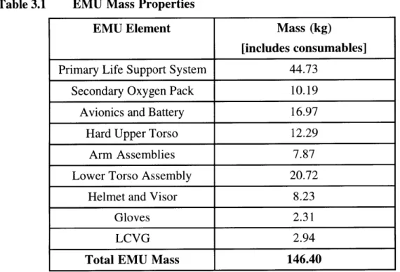
3.1 EMU Space Suit Model 40
3.1.1 Inertial Properties 40
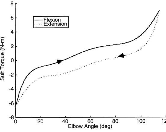
3.1.2 Suit-imposed Torques 41
3.1.3 Hysteresis Model 43
3.1.3.1 Introduction to Hysteresis 43
3.1.3.3 A Geometric Interpretation 47
3.1.3.4 The Preisach Function 52
3.1.3.5 Numerical Implementation of the Hysteresis Model 56
3.2 Human model 61
3.2.1 Skeletal Model 61
3.2.2 Muscle Models 62
3.2.2.1 Torsional Equivalent 63
3.2.2.2 Lumped Muscle Models 64
3.3 Simulation Method 65
3.3.1 SD/FAST Framework 66
3.3.2 Payload Translation Task 66
3.3.2.1 Rigid Lower Body 68
3.3.2.2 Compliant Lower Body 69
4. RESULTS 69
4.1 Hysteresis Model Test 69
4.2 Payload Translation Task 72
4.2.1 Rigid Lower Body 72
4.2.2 Compliant Lower Body 78
5. DISCUSSION 85
5.1 Hysteresis Model Test 85
5.2 Payload Translation Task -- Rigid Lower Body 86 5.3 Payload Translation Task -- Compliant Lower Body 87 6. CONCLUSIONS AND RECOMMENDATIONS FOR FUTURE WORK 91
7. REFERENCES 96
APPENDIX A: TRANSITION CURVE AND MESH CONSTRUCTION CODE 100
APPENDIX B: TEST FUNCTION FOR F(A,B) MESH 107
APPENDIX C: VISUALIZATION PROCESSING FOR MESH TEST 111
APPENDIX D: ELBOW JOINT TEST 113
APPENDIX E: SIMULATION CODE 118
List of Figures
Figure 2.1 Historical and Future NASA EVA Time [NASA, 1996]. 16
Figure 2.2 Early Pressure Suits. 21
Figure 2.3 Four-layer construction of the Mercury space suit. 22
Figure 2.4 Gemini (left) and Apollo (right) space suits. 24
Figure 2.5 Space Shuttle EMU multi-layer soft shell construction. 27
Figure 2.6 Volume change during joint flexion. 28
Figure 2.7 Nearly constant-volume space suit joint. 28
Figure 2.8 Finite element representation of a swatch of cloth. 30
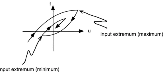
Figure 2.9 An empirically determined model of system f(x,u,t). 34
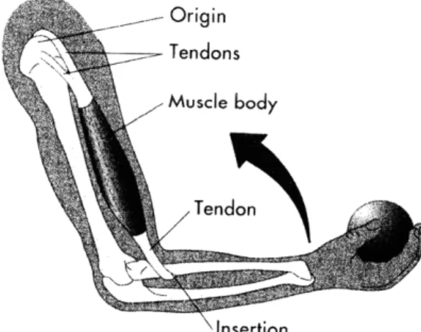
Figure 2.10 The human elbow joint is a third class lever. 35
Figure 2.11 Three-segment model of a human arm. 36
Figure 2.12 Hill-type muscle model [Winters, 1995]. 37
Figure 3.1 Hysteresis nonlinearity observed at the elbow joint of the EMU. 42
Figure 3.2 Hysteresis transducer. 43
Figure 3.3 Input-output time history for a hysteresis transducer. 44
Figure 3.4 Hysteresis transducer with local memory. 45
Figure 3.5 Hysteresis transducer with nonlocal memory. 45
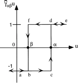
Figure 3.6 A simple hysteresis operator yap. 46
Figure 3.7 Hysteresis decomposition into simplest hysteresis operators ya. 47
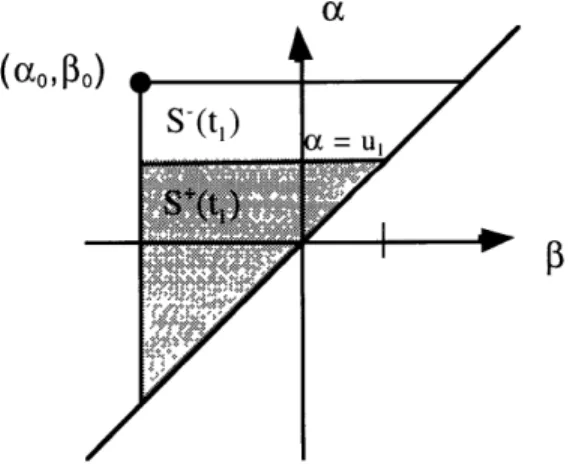
Figure 3.8. The a _> half-plane. 48
Figure 3.9 Triangle T at time t,. 48
Figure 3.10 Region S'(t2), bounded by the lines a = ul and P = u2. 49
Figure 3.11 The staircase interface I(t). 50
Figure 3.12 Angle versus torque curve for a space suit joint, with saturation limits. 51
Figure 3.13 EMU-modified half-plane a P3. 52
Figure 3.14 First-order transition curves. 53
Figure 3.15 The f-u plane (left) and a-3 plane (right) during a first-order reversal. 53
Figure 3.16 Subdivision of S'(t) into multiple trapezoids. 55
Figure 3.17 The discretized region T. 57
Figure 3.18 The angle O(a',P'). 58
Figure 3.19 The complete set of first-order transition curves for the elbow joint. 59
Figure 3.20 Cells bounded by either three or four vertices. 60
Figure 3.21 Human skeletal model. 61
Figure 3.22 Torsional equivalent muscle models. 63
Figure 3.23 Agonist-antagonist lumped-muscle model. 64
Figure 3.24 Schematic representation of a Hill muscle model. 65
Figure 3.25 Simulation flow diagram. 66
Figure 3.26 Spartan payload translation task. 67
Figure 3.27 Bias position qbias for the elbow joint. 68
Figure 4.1 Elbow joint trajectory and suit-imposed torque during model test. 70
Figure 4.2 The surface f(a,) at t = 60 seconds (elbow joint test). 71
Figure 4.3 Sequential astronaut position during payload translation task, rigid lower body. 72
Figure 4.4 Joint positions during payload translation task, rigid lower body. 73
Figure 4.5 Joint torques for payload translation task, rigid lower body. 76
Figure 4.6 Cumulative joint work for payload translation task, rigid lower body. 77
Figure 4.7 Astronaut position during payload translation task, compliant lower body. 79 Figure 4.8 Joint positions for payload translation task, compliant lower body. 80 Figure 4.9 Joint torques for payload translation task, compliant lower body. 83 Figure 4.10 Cumulative joint work for payload translation task, compliant lower body. 84
List of Acronyms
d.o.f. degree(s) of freedom
EMU Extravehicular Mobility Unit EVA Extravehicular Activity
ILC International Latex Corporation JSC Johnson Space Center
LCG Liquid Cooling Garment
LCVG Liquid Cooling and Ventilation Garment LEO Low Earth Orbit
MIT Massachusetts Institute of Technology
NASA National Aeronautics and Space Administration PGA Pressure Garment Assembly
PLSS Portable (Primary) Life Support System RMS Remote Manipulator System
STS Space Transportation System
1. INTRODUCTION
Chapter One addresses the specific motivation for developing a space suit dynamic model and the more general motivation behind the current research effort in
extravehicular activity (EVA) computer simulation. It discusses the place of a space suit model in the overall simulation framework, and then details the specific objective and contribution of this thesis.
1.1 Motivation
The extravehicular mobility unit (EMU) space suit presents a mechanically complex, highly constrained working environment that limits astronaut motion considerably. As a result, numerous studies have attempted to characterize the particular workspace to which a suited astronaut is restricted [Reinhardt, 1989]; dimensions aid extravehicular activity planners in describing feasible EVA tasks, assuring that the reach envelope required for a given task will not exceed the reach envelope available to the astronaut. Computer-aided design facilities have already incorporated similar data into EVA planning software [Price, 1994; Pardue, 1996]. Workspace definitions, however, do not take into account the appreciable dynamic effects that a
146 kg space suit with significant joint torques will have on astronaut strength and mobility during an EVA task. Data is only beginning to appear with regard to available suited strength [West, 1989; Dionne, 1991; Morgan, 1996], and thus make its way into the EVA design
process. Even if armed with this data, EVA designers will only be able to make rough estimates of strength needed vs. strength available for a given task. These static measurements of
performance do not allow for the direct comparison of tasks that have been choreographed in a particular way, or of the astronaut effort required to execute each task in terms of total work performed, distribution of work among the various muscle groups, and issues involving the gradual onset of fatigue.
Computer simulation of EVA tasks provides one solution to these questions, allowing designers to observe how space suit effects may influence overall EVA performance. A dynamic space suit model can record astronaut movement through a simulated EVA task and apply appropriate inertial and suit-generated loads to crewmember limbs during the simulation.
The resulting time histories of position, velocity, and acceleration for various body segments then allow for quantitative analysis of the work being performed. Problem areas can be identified, and choreography refined to account for predicted complications.
This method also provides a six-degree-of-freedom arena in which the simulated EVA crewmember can work, allowing for unrestrained multibody interactions in a microgravity environment. Although physical simulators such as the Johnson Space Center's neutral buoyancy facility are excellent for both astronaut training and developing EVA choreography, these and other ground-based devices have inherent limitations; it has been shown that
quantitative pre-flight analysis of EVA tasks in six degrees of freedom can help to reveal the sometimes quite subtle differences that accompany work in an EVA setting [Schaffner, 1997].
1.2 Objective and Contribution
The objective of this research effort is to accurately model and simulate astronauts during the execution of an EVA task, providing a six-degree-of-freedom environment in which to
explore new EVA tools and techniques. This thesis specifically addresses the EMU space suit, investigating possible models for the suit, developing computer code for model implementation, and presenting results based on application of the space suit model to EVA task simulation.
Accurate modeling of the EMU space suit is essential to the realistic simulation of any EVA task. The astronaut is unavoidably forced to work within the confines of the suit, and it
affects every movement he or she makes for hours on end. The EMU's heavy "backpack," the primary life support system (PLSS), generates unfamiliar inertial loads, the structure of the suit places hard limits on the available workspace, and, most importantly, the suit imposes restrictive torques on astronaut motion. These effects combine with the unfamiliarity of working in a
microgravity environment to pose significant hazards to an EVA crewmember. The objectives of this thesis are therefore to create a model of the space suit, and to explore its applicability to EVA simulation.
To meet these goals, an original dynamic model of the EMU space suit is developed, based on data obtained from NASA and Hamilton Standard (Windsor Locks, CT). The Preisach model is introduced as a mathematical technique for modeling suit joint characteristics, and
implemented in computer code on an SGI Indigo2 workstation. Finally, the model is tested during three simulations of astronaut motion during EVA.
1.3 Summary of Thesis
This introductory chapter presents the motivation and objectives of this thesis, followed by chapters discussing the background, methods, results, discussion, and final conclusions of the research. Chapter Two introduces extravehicular activity as a key enabling technology for
spaceflight, providing a brief history of past EVA missions and considering various options for the simulation and training of EVA operations. It then touches on the history of the EMU space suit, focusing on construction issues and critical technologies. A short summary of methods for flexible fabric modeling is included, followed by arguments for empirically based, data-driven models. Finally, several biomechanical models for describing the underlying human operator are presented, with an emphasis on properly choosing the level of detail appropriate for this research.
Chapter Three discusses the methods used to create a dynamic model of the EMU, representing the main contribution of this thesis. Basic inertial properties are examined, and a modified Preisach model for hysteresis is introduced to allow accurate representation of imposed space suit joint torques. The implementation of the hysteresis model is discussed in detail, and described in terms of existing space suit data. Musculoskeletal models for the astronaut are then addressed, considering several different lumped-parameter approaches. Finally, the multibody dynamic simulation methodology is described along with several simulations created to test the EMU model.
Chapter Four presents the results of a test simulation for the hysteresis model at the EMU elbow joint, and two payload translation simulations involving the Spartan astrophysics payload.
Astronaut position during each simulation is displayed in terms of individual joint angles, and sequential diagrams of crewmember position are included to facilitate interpretation of the kinematics data. Torques at each joint are calculated, and total cumulative work is computed from these torques and their corresponding joint velocities.
Chapter Five discusses the simulation results, highlighting interesting aspects of the data and comparing the results to previous research. The elbow joint test simulation is discussed first, followed by the rigid body payload translation and the compliant body payload translation tasks.
The EMU model is observed to have a dramatic effect on astronaut posture during simulated EVA tasks, and to increase the workload of a suited crewmember in unexpected ways. Finally, the work of this thesis is compared to existing research and similar investigations, highlighting possible opportunities for collaboration and technology transfer.
Chapter Six reviews the main contributions of this research, and discusses potential applications for the EMU model. It includes recommendations for experimental work that could be performed to help refine the model, and discusses opportunities for future research in the areas of space suit modeling and EVA simulation. A summary of this thesis is provided, emphasizing the gap in existing simulation technology filled by this research. Future work in EVA computer simulation based on this suit model will improve crewmember training and comfort, and will work with other simulation methods to provide an integrated environment for EVA design and analysis.
2. BACKGROUND
This chapter presents background information relevant to modeling the extravehicular mobility unit space suit. It begins by familiarizing the reader with extravehicular activity in general, providing a brief history of humans in space and then outlining ways in which computer simulation can improve EVA preparation and effectiveness. The text first highlights several milestones in EVA work throughout the space program, with emphasis on the importance of EVA as a key enabling technology for space travel. Various methods of EVA preparation and training are then discussed, indicating how computer simulation complements existing
technologies and provides added insight for EVA missions.
The second section traces space suit development over seven decades, illustrating how early mobility problems were overcome by ingenuity in suit design and increased interest from the space program. It chronicles the various improvements made on successive EVA suits, which ultimately led to the design of the EMU in service today on the Space Shuttle; the current EMU is then described in greater detail.
As a survey of possible models for the soft fabric construction of the EMU space suit, the third section presents a brief history of fabric modeling. It explores connections between the textile industry and computer graphics research, and documents ways in which these
communities have attempted to model woven material. Several finite-element approaches to textile modeling are discussed, and shown to be impractical for the scale of the EMU model and EVA simulation. Arguments are then presented for the empirically-based model chosen to represent the space suit.
The final section touches on biomechanical models for the human operator inside the space suit. The human model is an essential feature of any simulation analyzing or attempting to predict human motion, and many levels of model complexity are available. Several models for describing the musculoskeletal system are discussed, with an emphasis on properly choosing the level of detail appropriate for this research.
2.1 Extravehicular Activity (EVA)
Extravehicular activity refers to work performed in space, outside the confines of a larger vehicle. Astronauts wear protective space suits during EVA missions, and are generally attached to the larger spacecraft by means of foot restraints, handholds, and tethers. Crewmembers perform EVA tasks in a variety of situations, including planned repair or service missions to orbiting spacecraft, contingency problem-solving missions under unusual or emergency conditions, and EVA research tasks in preparation for greater challenges. Extravehicular activities are often mission-critical, and frequently involve multiple crewmembers performing delicate and complex tasks. Though daunting, these tasks are based on some prior experience in the space environment -- astronauts have been walking in space for over thirty years.
2.1.1 Historical Perspective
The first spacewalk took place in 1965, when Soviet cosmonaut Alexei Leonov emerged from his Voskhod space capsule to float free in space for over ten minutes, tethered to his
spacecraft by a 5 meter umbilical. This successful EVA demonstrated that a human being could exist somewhat comfortably in space, protected only by a pressurized suit from the cold vacuum outside. Leonov's pioneering excursion introduced a decade of rapid EVA progress for both Soviet and American space programs, improving technology and technique with every mission
America's first experience in EVA was the Gemini program, which experimented with various operational aspects of working in space, including the positioning of foot restraints, handholds, and controlling crewmember exertion and fatigue. It was not until the Apollo program, however, that an American space program utilized the full operational capability of the EVA astronaut.
Apollo crewmembers accumulated 160 total hours of extravehicular activity time exploring the lunar surface, and their ability to conduct experiments while suited illustrated the great scientific value of EVA capability. Soil and rock samples were collected on a regular basis, and short trips from the lander were executed flawlessly. The Apollo program led to swift advances in suit design, and it demonstrated the feasibility of pressure suit use on a planetary surface.
EVA continued to prove its value during the Skylab program, as early as the arrival of the first crew. A damaged hull and missing solar panel created problems from the start, but an impromptu EVA allowed the Skylab II crew to deploy a second solar panel and to bring the station back to operational status. Problems during the space program showed that emergency and other unplanned situations were well suited for EVA solutions, allowing a skilled astronaut to bring human problem-solving abilities and operational flexibility directly to the worksite.
During the late Apollo and Skylab programs, the Russians experienced some difficulty with EVA reliability, but they resumed operations in 1977 during the Salyut 6 program. Several maintenance and repair EVA missions were successfully completed, paving the way for regular EVA excursions during the Salyut 7 space station program. Russian cosmonauts carried out multiple scientific experiments during EVA, and continued to maintain the capability to perform contingency EVAs in emergency situations.
The United States began performing EVA missions under the new Space Transportation System (STS), also known as the Space Shuttle, in 1983. EVAs were performed routinely through 1985, giving American astronauts valuable experience working in space. Astronauts performed both planned and contingency EVA missions, exploring the use of special EVA tools and work techniques. Making history in February 1984, Bruce McCandless successfully
demonstrated the Manned Maneuvering Unit (MMU) as the first free-flying crew propulsion device to be used in space.
More recently, two service missions for the Hubble Space Telescope (HST) dramatically demonstrated the necessity for and effectiveness of the EVA crewmember. Following the disastrous news that the multibillion-dollar space telescope was flawed, four EVA astronauts on Hubble Space Telescope Service Mission 1 (HST SM-01) spent a record-setting five consecutive days of EVA upgrading the damaged optics. Extensive pre-flight training helped the mission to its spectacular success, which generated months of positive media exposure for NASA and the entire space program. A key benefit of EVA programs, the human drama of astronauts doing their work in space is a captivating scene with which to encourage interest in the space sciences throughout the world.
The success of critical EVA missions like these depends greatly on NASA's commitment to extensive pre-mission EVA preparation and training. Without the practice afforded by endless hours of training, EVA missions would be far more hazardous and
unpredictable than the forgone successes that modern spacewalks have seemingly become. The space environment is unforgiving, however, and ground-based training does not always provide a complete picture of what is to come; new methods such as computational simulation are currently being developed to complement and improve upon existing physical simulation methods.
2.1.2 Extravehicular Activity Simulation
Extravehicular activity takes place in an environment utterly unfamiliar to human beings. Minute forces can move massive objects with the greatest of ease, moving around is more an
issue of pointing in the right direction and controlling angular momentum than moving any one part of your body, and all activities are performed inside the giant shell of a space suit. NASA recognized some of the problems that might be encountered if astronauts were expected to adapt
instantaneously to the microgravity environment, and initiated an extensive EVA training and mission preparation program to help acclimate crewmembers to differences they might encounter.
NASA began with physical simulators, hoping to give astronauts work experience in a setting that approximates microgravity. Large water tanks were constructed as neutral buoyancy training facilities, e.g., the large facility at Johnson Space Center in Houston, and since then every
planned EVA mission has been rehearsed in the water. Immersion in water can provide a zero-gravity "feel" by canceling the force of zero-gravity with buoyancy, but it also adds the phantom forces of hydrostatic drag and water displacement inertia to counteract astronaut motion. EVA rehearsals taking place in the water can actually train astronauts to expect these false forces, conditioning their neuromuscular system to anticipate water drag and pressure nonexistent in space, and thereby hinder EVA performance. Additionally, astronauts have noted that the work environment is not exactly the same: letting a tool drop in the water tank sends it to the bottom within seconds, while the same tool in space would remain motionless in front of the astronaut.
Eliminating water's unwanted viscosity, air-bearing floors have also been used extensively to train astronauts in two-dimensional translational motion. Small jets of air hold astronauts and the objects they might interact with, such as satellites, away from the ground on a frictionless cushion of air; this simulator has proven very useful for linear translation and mass-handling tasks, helping astronauts to better judge the responses of massive yet weightless objects. Unfortunately, the three degrees of freedom (including rotation) that this simulator provides only reproduce 50% of the true environment, and attempting to include more degrees of freedom via some mechanical apparatus only serves to introduce unwanted friction.
Additionally, the friction forces present in the floor itself and the small air drag encountered with large objects can affect the realism of a simulated EVA condition.
Many of these problems are solved by using a specially modified aircraft to fly parabolic, zero-gravity trajectories; NASA's KC-135 training aircraft was designed for just that purpose. Passengers on this aircraft are provided with approximately 25 seconds of free-fall time, during which they are free to move about the weightless environment in six degrees of freedom. The unlimited range of motion creates a very realistic simulation, but the limited available space inside the fuselage of the aircraft usually constrains astronauts to intravehicular activity (moving about the interior of a spacecraft) simulations. Additionally, the limited duration of weightlessness does not provide a very good approximation of a six or seven hour EVA. To make up for this deficiency, pilots fly 40-50 repeated sequences of zero-g parabolas and 2-g pullouts, but this usually serves only to induce motion sickness in the cabin. Vomiting inside a space suit would be extremely dangerous, creating a real possibility of clogged air lines and choking; therefore, EVA tasks are usually not simulated on KC-135 aircraft.
Each of these simulation methods has a specific type of task for which it is well-suited, and the various simulators have been used in combination to provide adequate venues for research and training certain aspects of EVA missions. They are all limited, however, by the realities of a one-g field on earth. Combinations of various physical simulators will never exactly reconstruct the conditions experienced on orbit, and may introduce difficulties during spaceflight if astronauts learn to expect forces or torques that are merely artifacts of an imperfect simulator. Additionally, physical simulators are extraordinarily expensive to operate for the amount of time that complicated EVA missions require. The Hubble servicing mission, for example, spent millions of dollars on operations training in the JSC neutral buoyancy facility alone. With the severe demands of International Space Station EVA missions looming on the horizon (Figure 2.1), there is a clear need for more economical means of simulating EVA tasks that might help to fill in the gaps left by physical simulators.
Forecast 250 200 150 100 91 92 93 94 95 96 97 98 99 Calendar Year 00 01 02
Historical and Future NASA EVA Time [NASA, 1996]. Figure 2.1
Computational dynamic simulation embraces this role well, skirting the limitations of physical simulators by moving into the virtual computer world, while keeping time and expense to a minimum. Quantitative analysis of EVA operations is possible without large-scale
experimental devices, and produces results important to the EVA community [Schaffner, 1995]. Problem areas can be identified, and EVA choreography refined to account for predicted
complications. This method also provides a full six-degree-of-freedom arena in which the simulated EVA crewmember can work, allowing for unrestrained multibody interactions in a microgravity environment. Computer simulation can tease out the subtle differences between physical simulation and the actual operation, complementing existing simulation technologies and ensuring that EVA will continue to enjoy the successes for which it is famous.
These simulations would be lacking an important characteristic, however, if they failed to account for the dynamic effects of the EVA crewmember's space suit. The pressure suit has been an integral part of the aerospace world since World War II, and deserves a special place in
space history.
2.2 The Space Suit
Space is, quite simply, the most hostile environment known to human life. None of Earth's myriad life support mechanisms exist in the spaceflight environment, and new and threatening elements such as space debris only compound the problem. Astronauts must therefore replicate Earth's atmosphere in tightly sealed and protected spacecraft, bringing the
necessities of life with them into space.
From time to time it is necessary for astronauts to leave the confines of their vehicle and address problems directly at the worksite. It is impossible to leave the spacecraft without some form of environmental protection, and for this reason, a miniature spacecraft able to perform all requisite life support functions was developed: the space suit.
2.2.1 Environmental and Physiological Concerns
As early as the nineteenth century, pioneering aviators had already discovered many of the dangers presented by the unforgiving aerospace environment. High-altitude balloonists knew that any flight above three or four thousand meters required warm clothing to protect against cold
temperatures and a special oxygen supply to keep the pilots from passing out. As these early adventurers traveled to higher and higher altitudes, they quickly discovered that oxygen alone was insufficient to keep them alive, and that a positive-pressure delivery system was necessary to force oxygen into their lungs.
These balloon pilots had directly experienced the atmospheric changes that take place during the transition from sea-level to spaceflight altitudes. At sea level, the atmosphere is composed primarily of four gases at a total pressure of 101.3 kPa, but this relatively thick layer disperses rapidly with altitude (Table 2.1).
Table 2.1 Atmospheric Composition at Sea Level and 5,500 m.
Gas Concentration Partial Pressure at Partial Pressure at Sea Level (kPa) 5,500 m (kPa)
Nitrogen 78.08% 79.1 38.4
Oxygen 20.95% 21.2 10.3
Argon 0.93% 0.9 0.4
Carbon Dioxide 0.03% 0.03 0.01
The partial pressure of oxygen (ppO2), which is the net contribution of oxygen molecules to the overall pressure, has decreased to 10.3 kPa by 5,500 m; humans cannot function to make intelligent decisions at partial pressures of oxygen lower than 13 kPa. Therefore, all excursions to high altitude require a special apparatus to provide the pilot with a minimum 13 kPa ppO2.
This can be achieved by either increasing the concentration of oxygen relative to other
atmospheric gases, or by providing a higher total pressure of all gases and thus increasing the ppO2 as well. In space, there is no atmospheric pressure -- a space suit must provide a minimum
13 kPa 100% 02 environment for astronauts to function normally.
In addition to the problem of atmospheric composition, there are a number of unique aspects to the space environment that affect the ability of humans to do work. These include thermal, radiation, and micrometeoroid hazards that must be met with some layer of protection between the astronaut and the outside environment. At a typical Space Shuttle orbiting altitude of 200 km, the EVA crewmember must face a temperature of 582' C, a total pressure of less
direct measure of heat at this altitude, helpful effects such as convective cooling on Earth are not present, and heat transfer must be addressed in special ways.
Electromagnetic radiation comes to low earth orbit (LEO) in 2 forms: solar cosmic radiation (SCR) and galactic cosmic radiation (GCR). SCR comes from two types of ionizing radiation emitted by the sun, both in the form of high-energy particles (protons, electrons, and photons). First, the solar wind produces a stream of ionized particles (protons and electrons) at a density of about 5 cm-3 that blows toward Earth, frequently becoming trapped in the Van Allen belts at 300-1200 km altitude. In addition to this continual solar wind, solar flares produced by storms in the solar magnetosphere generate high radiation doses in very short periods of time.
Galactic cosmic radiation, on the other hand, consists of high-energy particles and heavy nuclei originating beyond the solar system. Low altitude orbits are largely shielded from GCR radiation by the Earth's magnetic field; interplanetary or deep space travel, however, will be open to the effects of GCR and man-made shielding must be provided.
Micrometeoroids and other forms of space debris are yet another hazard in the space environment. The average flux of micrometeoroids through low earth orbit is poorly known, but most particles have masses below 10-6g. Still, the relative velocities of these objects can cause serious damage to spacecraft and space suits. Potentially an even greater danger are the more than 40,000 bits of space debris larger than 1 cm currently floating in earth orbit, left by previous operational or damaged spacecraft. Space suit design must take into account the possibility of puncture by such an object; literally billions of smaller particles are assumed to exist in the same orbital environment.
It is clear that designing a space suit to perform flawlessly under these harsh conditions is no easy task. Still, the spirit and dreams of mankind have led us to step boldly into this new
frontier, and counter the environmental hazards as best we can. Beginning with the first pressure suit for high altitude flight, space suit design work has progressed in both scientific
understanding and engineering acumen, and the current Space Shuttle EMU pays homage to those advances with its effective design.
2.2.2 A History of the Extravehicular Mobility Unit (EMU)
The space suit performs three basic functions: maintenance and constraint of the pressurized atmosphere necessary for life support, protection from environmental hazards, and provision for enough mobility to perform useful work. The life support system must control suit pressure, regulate the atmospheric mixture of gases, monitor and adjust temperature and
humidity, and supply all power, computer, and communications facilities for the astronaut; this integrated system is enclosed in the portable life support system (PLSS) mounted on the back of the EMU. The actual suit garment provides environmental protection, using a multi-layer construction to absorb micrometeoroid strikes, reflect harmful radiation, circulate air and cooling water, and contain the pressurized atmosphere. Finally, unique features are incorporated into suit construction that allow for unusually high mobility in a garment that resembles a large balloon. The complexities of such a design have intrigued engineers for nearly 70 years, and have yet to be perfected.
2.2.2.1 Early Suit Designs
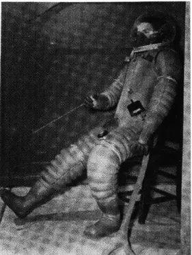
The first full pressure suits were manufactured by the B.F. Goodrich company in the late 1930s as an attempt to overcome the hazards of high-altitude aviation. Company engineer Russell Colley designed a series of pressure suits for the daredevil and adventurer Wiley Post, who was determined to achieve high-speed stratospheric flight. These primitive suits were molded in the shape of a seated pilot using liquid latex, and they held about 17 kPa when fully pressurized (Figure 2.2, left). An outer layer of cotton was then added for thermal protection, and metal rings were fitted about the knees to bunch the fabric, allowing for slight movement.
In the early 1940s, U.S. military aviation began to take an interest in pressure suit research and began to fund various efforts across the country. This new generation of suits maintained a pressure of 24 kPa, and they incorporated a new "tomato worm" design with segmented rubber bellows at the joints, allowing the wearer to move without changing the joint volume appreciably (Figure 2.2, center). Unfortunately, this was only true in the unpressurized case, and the suits invariably ballooned up to become rigid and uncomfortable when pressurized. Military aviators had no way of performing their assigned duties, e.g., sighting through and manipulating a bomb sight, while wearing such a suit, so it remained a research project with no operational status.
Figure 2.2 Early Pressure Suits.
The first full pressure suit (left), the tomato-worm design (center),
Lack of mobility remained the number one problem in pressure suit design until 1956, when the David Clark Company created the A/P22S-3 suit for the Air Force (figure 2.2, right). The suit incorporated a soft nylon netting on the outside of the pressure bladder, which
constrained the pressurized suit to a predetermined shape and effectively prevented it from ballooning out of control. The industry had been waiting for this critical breakthrough, and it represented the turning point in pressurized suit design. The resulting suit was fairly mobile, comfortable, and provided adequate thermal protection in its outer layers. B.F. Goodrich then took a similar approach, and improved upon David Clark's Air Force design for the Navy, with modifications including an automatic pressure control system, rotating joint bearings, and a robust ventilation system.
2.2.2.2 Mercury
In 1959, a newly created NASA selected the B.F. Goodrich Company over ILC and David Clark to produce the Mercury space suit. Their suit evolved during the course of the various Mercury missions, but retained a general 4-layer construction throughout (Figure 2.3). An outer layer of aluminized nylon provided flame and abrasion protection for the astronaut. Just under that, neoprene-coated nylon enclosed the actual pressure vessel to provide insurance for leakage protection. The pressure bladder was made of vulcanized, double-walled nylon, ventilated along its inner wall for air circulation and cooling. Finally, the astronaut wore long-john
underwear with interwoven patches that circulated air for comfort and temperature control.
l _Aluminized Nylon
Neoprene-coated Nylon
Vulcanized, Double-walled Nylon Long Underwear
Figure 2.3 Four-layer construction of the Mercury space suit.
Mobility was somewhat improved in the Mercury suits; Colley and the Goodrich engineers addressed the constant-volume problem in a slightly different manner than the David Clark Company. Instead of a whole-body "linknet," they sewed inelastic restraining cords along the elbow and knee joints to prevent the pressurized suit from expanding (see section 2.2.3). Combined with their rotating joint bearings, many of the initial mobility problems associated
with full-pressure suits had been solved.
2.2.2.3 Gemini
The Gemini program provided the first real test of American space suits: outer space. For the first time, a space suited astronaut would attempt to work outside the protective
environment of the spacecraft. Additionally, the suit would have to be comfortable enough for multi-day missions; the crew would wear different intravehicular activity (IVA) suits while inside the capsule and don special extravehicular suits for EVA. Although many variants were used over the course of the 2-year Gemini program, the standard Gemini space suit was the David Clark Company's G4C (Figure 2.4).
The most significant change from the Mercury suit was the implementation of David Clark's "linknet" restraint system, instead of the Goodrich restraining cords that were sewn on the outer edges of knee and elbow joints. The linknet layer was similar in design to David Clark's A/P22S-3 Air Force pressure suit: a loosely interconnected network of light but strong fibers was woven throughout the suit, forming a fishnet-like layer to restrain suit volume. The Gemini IVA suit, worn inside the spacecraft, consisted of five layers; the EVA suit added an
additional 17 layers for environmental protection during spacewalks.
Like the Mercury suit, astronauts wore long underwear as a base layer, connected to biomedical sensors attached to the body. The next two "comfort" layers of the basic Gemini
suit were oxford nylon layers of different weights that helped to distribute ventilation gas over the entire body and to separate the astronaut from the subsequent pressure bladder. The bladder itself was fabricated from neoprene-coated ripstop nylon, and the restraint layer directly above was the innovative linknet. IVA suits then added a covering layer of Nomex, called Dupont HT-1 (High Temperature), which protected the suit against snags from spacecraft instrumentation and sharp objects.
The EVA suit retained the same pressure bladder and restraint layer configuration, but replaced the IVA suit's single Nomex layer with a thick, protective covering fabricated from multiple layers. Two inner HT-1 neoprene-coated Nomex layers served as micrometeoroid protection, and they were covered by 14 layers of alternating aluminized Mylar and
superinsulating unwoven Dacron for thermal and radiation protection. Finally, the suit was covered with a third Nomex layer to give abrasion and further micrometeoroid protection.
UNDERWEAR
COMFORT LAYER
PRESSURE BLADDER
RESTRAINT LAYER
(LINK NET)
BUMPER LAYERS HT-I
ALUM IN ZED THERMAL
LAYER FELT LAYER HT-I
\OUTER LAYER HT-I
Gemini astronauts performed both stand-up (in which the astronaut merely stands in the open hatch area and never leaves the vehicle) and complete EVA missions, proving the feasibility of doing useful work in space. Complications developed during several EVAs, but provided good experience for future missions. For example, Gemini 9-A astronaut Gene Cernan experienced problems keeping his body within his EVA work area, increasing his workload while attempting to complete several tasks. Simply maintaining body position required so much energy that he overheated and suffered early fatigue, cutting the mission short. Important lessons were learned about EVA restraints and astronaut placement, contributing to future Apollo
improvements.
2.2.2.4 Apollo
The Apollo program saw several key changes in space suit design. The primary suit was manufactured by the International Latex Corporation (Dover, Delaware) under a contract from Hamilton Standard, the overall life support integrator. It included advances in joint design, using
a flexible convolute design rather than the block-and-tackle mechanism used to physically size the suit, and waist and neck flexion joints were added to provide sitting capability and greater
comfort during long-duration EVAs (Figure 2.4). All together, the Apollo Lunar EVA suit was composed of 25 separate layers. The suit also replaced umbilical life support lines with a
portable life support system (PLSS) designed for remote operation on the lunar surface. The complete suit system, including the PLSS, was designated the extravehicular mobility unit (EMU).
Problems with overheating on the Gemini missions were taken seriously during Apollo suit design. Anticipating much greater workloads during lunar EVAs than zero-gravity Gemini missions, improvements had to be made on Gemini's air-cooled suit. The long underwear worn by Gemini astronauts was replaced in the Apollo suit by a three-layer liquid cooling garment
(LCG), comprised of a lower nylon layer, a vinyl tubing layer which circulated cooling liquid, and an upper nylon spandex layer to restrain the tubing. The circulating water could transfer heat away from the astronaut by direct conduction, and virtually eliminate perspiration.
The pressure garment assembly (PGA) was similar to the Gemini design, with some modifications. ILC engineers retained the general linknet design to restrain each joint, adding a
cable/block-and-tackle assembly to further restrain the shoulders and knees. The outer EVA covering was also similar to Gemini, incorporating the alternating Mylar and Dacron layers, but it added a Kapton layer for fire and thermal radiation protection as well as Teflon outer coverings for abrasion and flame resistance.
Apollo astronauts tested the EMU thoroughly during operations on the lunar surface. It was found that some joints, especially lower-body regions, were extremely stiff during extended periods of walking on the surface; similarly, problems in the thigh area of the suit created balance instabilities, and the lunar gravity caused the astronauts to lean forward while upright. Apollo 17 astronaut Eugene Cernan reported great difficulty operating a rock drill while encumbered by a pressurized suit, and noted a rise in his heart rate. Still, surface EVAs were extraordinarily successful and produced groundbreaking scientific experiments, proving yet again the necessity for EVA capability.
2.2.2.5 Shuttle
The current operational space suit for the Space Shuttle program is the EMU manufactured by Hamilton Standard (PLSS) and ILC (fabric suit). The EMU is a direct
descendant of the Apollo suit, designed with many of the same features as the 1970 version. The space suit is constructed from two pieces: a hard upper torso (HUT) and a soft-shell pressure garment surrounding the limbs. The HUT is the main structural member for the suit, to which
all other pieces are mounted. It is connected via bearings to the soft fabric arms and the lower torso assembly (LTA), also made of fabric. The PLSS is mounted to the rear of the HUT; this is
a key dynamic aspect of the suit, for it moves the suited astronaut's center of mass to the rear of its usual location.
The astronaut still wears a liquid cooling and ventilation garment (LCVG), made from nylon and spandex with a tricot lining. Instead of Apollo's separate cooling tube layer,
ethylene-vinyl-acetate tubes are woven throughout the spandex layer. The soft-shell pressure garment is fabricated from urethane coated nylon, covered by a woven Dacron restraint layer. As with the Apollo EVA suits, outer environmental protection is provided by a thermal and micrometeoroid protection garment (TMG). The TMG liner is neoprene-coated ripstop nylon, shielded by five layers of aluminized Mylar with a Dacron backing for thermal and radiation protection .Finally, a
Teflon-coated blend of Kevlar and and tear protection (Figure 2.5).
Nomex synthetic fibers covers the suit for puncture, abrasion,
Ortho-fabric (Teflon-coated Kevlar/Nomex blend) Aluminized Mylar backed with Dacron insulation Neoprene-coated Nylon
Dacron with interwoven axial restraint lines Polyurethane-coated Nylon (pressure bladder) Nylon/spandex blend with interwoven cooling tube Nylon acetate comfort layer
Space Shuttle EMU multi-layer soft shell construction.
The multi-layer construction is somewhat bulky, and restricts motion largely to the central workspace in front of the astronaut. The space suit and life support system weigh a combined
146 kg when fully charged with consumables for EVA operation; the added mass makes it critical to move with slower, determined motions to prevent needless energy expenditure while moving the mass of the suit.
The enclosed suit is also pressurized to 29.6 kPa, substantially lower than Shuttle cabin pressure but high enough to prevent decompression sickness during the transition from cabin to
suit pressure, following a brief 1-3 hour prebreathe. Higher pressure suits would allow for a shorter or eliminated prebreathe stage before EVA operations, but soft-shell high pressure suits would encounter more substantial forces due to changing volume within the suit. Pressure and volume issues contribute substantially to the suit forces imposed on an astronaut, and are a continual challenge to EVA designers.
2.2.3 The Constant Volume Challenge
Changing the volume of an enclosed space, like the Shuttle EMU, requires work. If the EMU elbow joint is represented by a simple cylinder, then the enclosed volume is r D2L, where
4D
is the cylinder diameter and L is the length [Newman, bent, the1997]. If the cylinder is now D is the cylinder diameter and L is the length [Newman, 1997]. If the cylinder is now bent, the Figure 2.5
~LMMMYYkRAKWYC~aRIMY-' IRL~YI~Y~P16BBAL~B~
inside edge collapses while the outside edge remains extended, and the enclosed volume is reduced (Figure 2.6).
V = 44D2L
Figure 2.6 Volume change during joint flexion.
Assuming a pressure-regulated environment like the EMU, the reduction in volume under constant pressure requires work:
W = PdV P( VINITIA L - VFNAL ). (2.1)
Under these conditions, the elbow joint would require over 230 Newtons of force to move. This is a clear impossibility for astronauts who would like to do useful work in space over long periods of time. Fortunately, ingenious solutions such as the David Clark Company's "linknet" restraint system have addressed this problem with great success, and advanced
development hard-shell suits have come close to eliminating the difficulty altogether. The current Space Shuttle EMU uses axial restraint lines to hold back the excess fabric in joints, providing room for the joint to expand on one side and contract on the other, thus maintaining a nearly constant volume (Figure 2.7).
Axial Restraint Lines
V =-4-D2L V = D2L+
Nearly constant-volume space suit joint. Nearly constant-volume space suit joint. Figure 2.7
I
I
In practice, however, the suit joint does not bend so that its centerline is exactly circular; unbalanced forces cause it to shift to the outside. Also, axial restraint lines are offset slightly from the centerline to ensure balance and stability at the joint. During motion, the axial restraints will provide close to constant volume, but over- and under-shoot by small amounts, especially near the edges of the range of motion at extreme angles of flexion and extension. Therefore the astronaut must ultimately do small amounts of work moving the joint from position to position. Additionally, bunching and expanding the actual fabric construction of the joint requires some degree of work.
Finding ways to maintain constant volume in a pressurized suit while providing adequate mobility for the suited individual is a problem that has challenged engineers for decades. Still, the current soft-shell suits must ultimately give way to changing volume at certain areas of a joint's workspace, and demand that mathematical models of suit dynamics take this property into account. Modeling methods for flexible fabric shells must also be explored, and used to design a model that closely approximates EMU parameters.
2.3 Flexible Fabric Modeling
Computer modeling of woven fabrics has gained great popularity in the last ten years, generating interest in both the textile industry and the computer graphics community [Breen, 1996]. Textile engineers are working to understand the mechanical properties of woven fabrics, including stress-strain relationships, thread interaction, and bending moments in order to design new fabrics and improve clothing performance. Most work has focused on experimental testing of various fabrics [Kawabata, 1980], but scientists have recently become more interested in apparel modeling as an aid to computer-aided manufacturing. Automated manufacturing in the clothing industry has traditionally been limited by the inability of robots to manipulate flimsy, flexible garments in deterministic ways; with an accurate model of fabric dynamics, however, machines on assembly lines could be programmed to pick clothes up, analyze them for defects, and pack them for shipping.
Computer graphics research, on the other hand, has continually been questing to produce more realistic "virtual actors" for computer animation and entertainment. The search has created great interest in ways to "clothe" actors in realistic garments, and to simulate objects like drapery
and tablecloths. What started out as a set of simple geometric tools for drawing realistic fabric has rapidly expanded into a plethora of detailed physical models describing fabric behavior, and
computer science is now looking to the textile industry for detailed descriptions of material properties. Most of the realistic models presented in the literature are finite element types, and they are explored first as a possibility for EMU fabric modeling.
2.3.1 Finite Element Methods
Finite element techniques represent cloth models as discrete triangular or rectangular grids with small masses at each intersection node (Figure 2.8).
Figure 2.8 Finite element representation of a swatch of cloth.
Forces between nodes are calculated as simple or complex differential equations based on Newton's Law, for example:
d2r - F +F + Fvlo + Fpastc), (2.1)
dt2 m external pring isco. astic
where r is the position of a node in 3-space and the forces are external, position-dependent, velocity-dependent, and plastic, respectively [Sakaguchi, 1991]. To obtain solutions for position and velocity of the nodes, equation 2.1 is discretized by a finite-difference method, resulting in a
set of simultaneous ordinary differential equations. These equations are then numerically integrated over time to produce trajectories for each node.
This type of general model allows scientists to simulate practically any situation by modifying the underlying forces F to model arbitrarily complex dynamic systems. For example, a simulation of fabric falling through a medium such as air or water might incorporate a full numerical implementation of the Navier-Stokes equations to develop aerodynamic forces for
inclusion in Fexternal above. Similarly, mechanical properties of the fabric can be lumped together in position-dependent and velocity-dependent categories to create visco-elastic forces within the material. These forces can be described at an even lower level by attempting to model the
behavior of individual threads in a woven textile environment, though the cost in processing time for such an effort becomes prohibitive [Keefe, 1994].
One important property that can be included in Fext is fabric interaction with itself and with other objects. Collision detection for rigid bodies is a well-explored subject [Moore, 1988], but it becomes more complex when dealing with a flexible cloth. Several investigators have explored algorithms for performing these computations [Lafleur, 1991; Yang, 1993], and, while successful, they suffer from excessive overhead computing node-to-node distances between the fabric nodes and underlying nodes representing the human shape. Most techniques therefore utilize a form of "windowing," which only computes collision algorithms for nodes known to be in proximity to one another. This solution would not be sufficient for the EMU case, though, if the model were attempting to simulate the various layers of the EMU garment. Multiple layers interacting at a large number of sites would pose a serious computational challenge to such an implementation.
The central drawback to physically-based modeling approaches is the sheer number of computations that must be performed to adequately simulate large sections of fabric. For
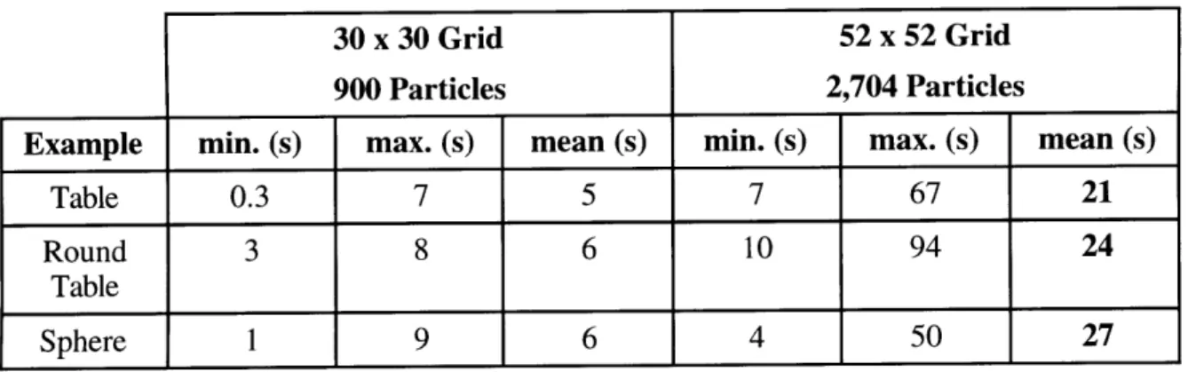
example, [Eberhardt, 1996] presents an excellent particle-based model for cloth deformation that shows great promise for application to EMU suit modeling efforts. His model is based on empirical cloth data from tension, shearing, and bending experiments, and accounts for important features such as anisotropy and hysteresis in the fabric data. Such an approach seems perfect for mimicking EMU suit performance, until the computation overhead is analyzed (Table 2.2). Even though this model is considerably faster than most finite-element methods, its processing times remain in the realm of frame-by-frame rendering, unsuitable for on-the-fly, real time
Table 2.2 Computation Time for Particle-Based Draping Simulation.
Computation times in seconds for a single timestep (40 ms) during simulation of a cloth draping over the indicated objects, on a Silicon Graphics R8000 workstation with additional
R8010 fpu [Eberhardt, 1996].
30 x 30 Grid 52 x 52 Grid
900 Particles 2,704 Particles
Example min. (s) max. (s) mean (s) min. (s) max. (s) mean (s)
Table 0.3 7 5 7 67 21
Round 3 8 6 10 94 24
Table
Sphere 1 9 6 4 50 27
A relatively small grid (52 x 52) of 2,704 particles requires almost 30 seconds to
compute a single frame of animation for the relatively simple task of draping cloth over a sphere, which is a mathematically well-described object. The human, on the other hand, is much more geometrically complex, and likely to be in contact with several sections of the EMU inner lining simultaneously. It is no wonder that many physically-based models are restricted to running on SGI Power or Cray supercomputers.
Finite element methods have been extremely successful in replicating the observed behavior of flexible objects in a limited number of situations. Unfortunately, the current
benchmark for such simulations is the "draping problem," in which a computer simulates a large section of fabric falling through a medium (air, water, oil) and coming to rest draped over an object such as a rod, sphere, or human. Though clearly beneficial to both the apparel industry and computer animation, these simulations have been optimized for specific conditions that would hinder performance in the more general EVA environment. Even if finite element calculations were practicable, an EVA suit model would still need to perform volume
calculations on the enclosed inner surfaces of the suit to recover the pressure forces generated as the suit volume changes while the astronaut moves about.
Combining these volume calculations with the already astronomical processor time required to simulate soft fabric on the scale of a full EMU space suit by finite element means, it is therefore impractical to use such an approach to model and simulate the suit during EVA
simulation. Considering the complexity and processing time required (up to 6 hours) to perform basic unsuited multibody dynamic simulations [Schaffner, 1997], discrete node-based methods
are simply too costly in terms of simulation efficiency.
The rapid growth of textile simulation and constant improvement in available processing power, however, show that finite element techniques may be an excellent way to model the EMU soft-shell construction in the future. Preliminary studies assessing the applicability of node-based approaches to the simulations of a multi-layer shell, such as the space suit, are encouraged. These studies may show that finite element methods should be strongly considered for the next generation of suit models.
2.3.2 Empirical Methods
Although finite element and other physically-based methods choose parameters (stress, strain, damping, shearing, etc.) empirically, they must ultimately break their system down into thousands of individual points or complex systems of equations, wasting valuable processor time. Fully empirical methods, on the other hand, simply find an input-output relationship between two parameters and apply the result directly. Though the resulting model is not derived from first principles and not nearly as elegant, the end result is identical as long as the data on which the model is based covers all possible areas of the operational state space.
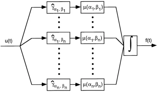
For the EMU, this requires data for each joint throughout its entire range of motion. All observed suit effects on the crewmember should be taken into account, including static loading, dynamic or velocity-related resistance, and increased angular inertia. The model then becomes a recording of observed effects in every possible condition, and simulation is just a matter of recalling the appropriate data and applying it at the proper time, as suggested in Figure 2.9.
Test Input Array
(covers all areas of the state space)
1) x =.
2) x= ... 3) x =.
Experimental
Data Collection
Observed Output DatabaseC
Simulation
)
Observed Output Database
X1 Y 1
x2 Y2
x3 " Y3
Simulated Output
-- y
An empirically determined model of system f(x,u,t).
This data-driven model is extremely fast (on the order of milliseconds), provided that the lookup database of observed outputs is organized in an efficient manner. If the output database is, in fact, complete, then the model will also be an exact model of the system f(x, u, t) and the system will be fully identified. In practice, however, it is usually impossible to obtain a full set of input-output data. This is not a problem with linear systems, where matching a few key
parameters to the data achieves complete system identification and easily extends the model throughout state space. For nonlinear systems, however, the form of the system may be entirely unknown. Therefore the model must be constructed from a few well-chosen test inputs, and interpolation used to extend the model into a continuous set of values. This paradigm is used in
Input x
![Figure 2.12 Hill-type muscle model [Winters, 1995].](https://thumb-eu.123doks.com/thumbv2/123doknet/14754193.581695/37.918.252.678.518.850/figure-hill-type-muscle-model-winters.webp)