l m
. INST.
14 JUL 79?7
DYNAMI CS OF THE IDUCTION SYSTE OF AN INTERNAL
COEBUSTION ENGINE
By
Robert H. Boden
B.A., University of Montana
1932
S.M., Massachusetts Institute of Technology
1934
Submitted in Partial Fulfillment of the
Requirements for the Degree of
DOCTOR OF PHILOSOPHY from the Massachusetts Institute _ 1936 of Technology .1/ Signature Department
of Author.
...
...
of Physics,May
26,
Signature of Professorin
Charge
of
Researcif .,..
..
...
.
S i g o n f C a t u r e h a i r m a n o f D e p a r t m e n t~~~~~~~~~~~~~~~~~~Signature
of
Chairman of Department
Committee on Graduate Students... · Fkm* " A Y
7
4
'
.-1936
--TABLE OF CONTENTS
Page
ACKNOWLETDGENT
I. INTRODUCTION ... .g..o*.oo... 1
II. TE WAVE
EQUATION,.
.. ...
*0·
... ·
*
.
1
III. THE EFFECT OF VISCOSITY... 22
IV. THE ACOUSTIC IMPEDANCE. ... ... 32
V. THE ACOUSTIC IMPEDANCE OF A PLANE VWAVE IN A TUBE. 35 VI. SPECIFIC ACOUSTIC IMPEDANCE IN A TUBE WIHII AN OPEf END ... ..*o.o ... 36
VII. TRANSMISSION ...
*
...*...
..
*
, ,*
41VIII, THE PROBLEM OF TEE INTAKE PIPE ... 48
IZ.
EXER~ENTAL
PROCEDURE.
...
..
...
..
~
.
...
64
X. CONCLUSION. .. . . ... ... .., . 72
XI
SUM.EARY...
...
.
*
..
....
.
..
...
74
XII. BIBLIOGRAPHY . ... *...,, 75
XIII.
EXPERIMENTAL
DATA-.2
0...
...
.. ....
..
76
ACKNOWLEDGMENT
This research has been carried out with the aid of
a grant from the National Advisory Committee for Aeronautics.
The author wishes to express his appreciation to Professor C. F. Taylor and Professor E. S. Taylor whose interest and efforts resulted in the grant mentioned. Professor E. S. Taylor was directly in charge of the experimental program. The author feels especially indebted to Professor P. M.
Morse for the encouragement and the time which he has
given during the course of this research. Mr. M. . McLeod of the Aeronautical Engineering department has assisted in
all experimental tests. Professor C. S. Draper first
mentioned the problem and pointed out some of its possi-bilities. Dr. R. M. Robertson helped with the calculations.
I. INTRODUCTION
The power output of an internal combustion engine
is directly proportional to the amount of air that can be forced into the cylinder per cycle. This amount is most
effectively increased by means of a mechanical supercharger. It may also be increased by the selection of a suitable
length for the intake pipe. Previous investigators have
found that the amount of air forced into the cylinder can
be increased almost twenty per cent by this method. The value of such an increase with no increase in the mechanical
complexity of the engine is easily recognized.
The previous work that has been done on the effect of the intake pipe has not been very complete, nor has it
resulted in a satisfactory picture of the events taking place
within the pipe. For this reason the author decided that an
investigation of the pressures in the intake pipe was of paramount importance. The first step in the research was to
secure a pressure-time recording instrument and mount it in the valve port of an engine. This, apparently, was the first time that any such record had been taken.
The engine selected for the research was the N.A.C.A. Universal test engine. It was selected as it had adjustments for varying the valve lift and timing and the compression ratio. The pressure-time recording instrument available was
the
M.I.T.
High Speed Engine Indicator
which was developed
by
Professors C. S. Draper and E. S. Taylor.
-1-Typical records of the pressure time ariation in
the valve port are shown in Fig. 1. The ordinate represents
the pressure in pounds per square inch and the abseissa is
the time for one revolution of the engine. The two traces
oceur on the record as the time for a complete alve eycle
is twice that for one engine revolution. As several hundred
valve eycles are ompleted in the course of making this
record, it is apparent that some sort of steady state
pressure wave phenomena is occurring in the intake pipe.
A little onsideration of the valve-piston mechanism
of the engine shows that its ation is ondueive to the
generation of pressure waves, A schematic diagram of the
engine and the ariation of the air velocity through the intake
port is shown in Fig. 2. The effect of the alve-piston eebanism
is evidently to send a pressure pulse out toward the open
end of the intake pipe, This pulse is sent oat periodically
each time that the valve is opened. Just as the valve opens
the velocity of the air in the inlet port is zero. An
instant later air has started flowing into the eylinders and
its velocity increases to a maximum and again becomes zero
when the valve closes. There is no velocity in the port
until the alve reopens again. This periodic 'driving
mechanima" will set up forced standing waves of sound in
of)
i
0
z
-j
0E
F-d
LL'LE
Hr
' i.
-- !I
I
1_ _
-
H
I
CAI T LLJ Y:0
tF-.) LLuz
Ct>-J
I.-.I :>r
-J
I> _J6
LUI C/)0
U
Lui>
...
6< UL I.L D -J I I I _-!I l - l . -- . raw x r . ., Iz = - - - -I I I I1 I I 0-- . 0--.. 4) --.III
Sound theory is eveloped on the assumption that the
space variation of the velocity and of the condensation due
to any excess pressure is small. This is not exactly trae
in the ase in question, but it is nevertheless a goo
approximation. The lengths of pipe for which supercharging
occurs are long. The pressure at the intake port may be
considerably above or below atmospheric pressure, but at the
open end of the pipe the pressure is always atmaospherio.
For this reason the rate ofS variation of the condensation
along the pipe due to any excess pressure is small.
There-fore it seemed advisable to use the simple sound theory to
study the progress of the pulse of excess pressure through
one valve cycle for several resonance oases.
At the open end of the pipe there is no excess
pressure, and a positive pressure is reflected. as a negative
pressure, while a velocity pulse is not hanged in phase.
At the valve end, when it is olose, a pressure pulse is
reflected with no hange in piase, but a positive velocity
pulse is reflected with change of phase.
The velocity at the valve end is assumed to be a
simple sinusoidal fanotion when the valve is open. The
assumption is also made that its maximum velocity will occur
when the piston velocity is a maximum. This is not exactly
correct, as will be discussed later. In this ase the
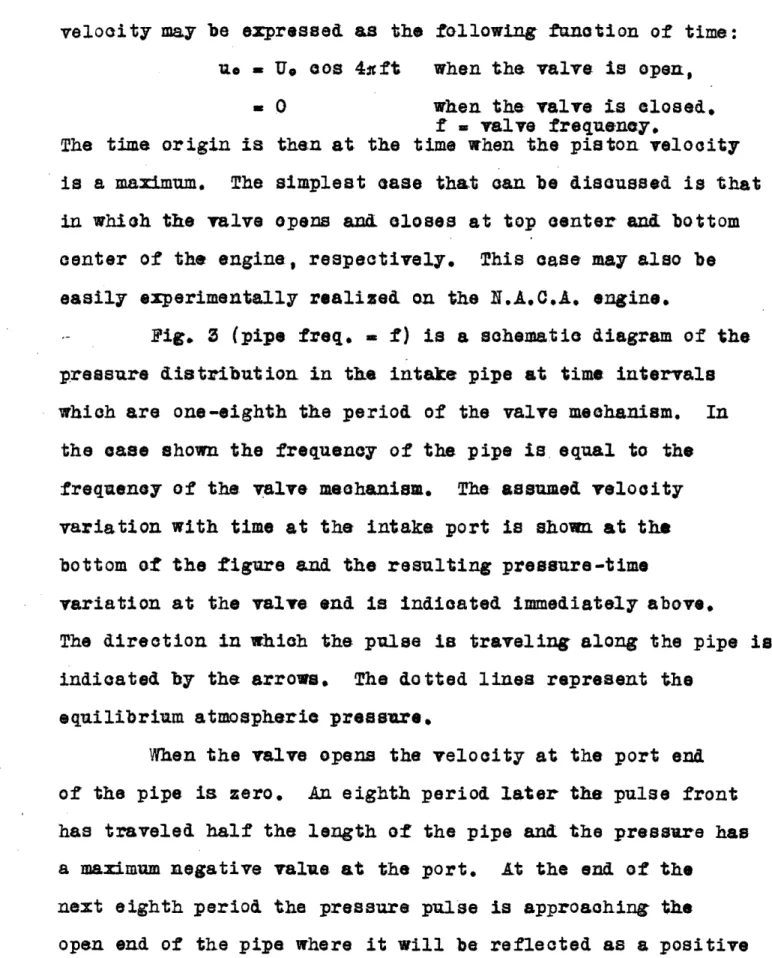
velocity may be expressed as the following fanction of time:
uo Ue cos 4ft when the valve is open,
= 0 when the valve is closed.,
f valve frequency.
The time origin is then at the time when the piston velocity
is a maximum. The simplest ease that can be iscussed is that in which the valve opens and. closes at top center and bottom
center of the engine, respectively. This ease may also be
easily experimentally realized on the N.A.C.A. engine.
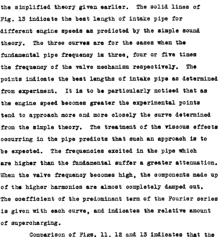
Fig. 3 (pipe freq. = f) is a schematie diagram of the pressure distribution in the intake pipe at time intervals
which are one-eighth the period of the valve mechanism. In
the ase shown the frequency of the pipe is equal to the
frequency of the valve mehanism. The assumed velocity
variation with time at the intake port is shown at the
bottom of the figure and the resulting pressure-time
variation at the valve end is indicated immediately above.
The direction in which the pulse is traveling along the pipe is
indicated by the arrows. The dotted lines represent the
equilibrium atmospheric pressure,
When the valve opens the velocity at the port end
of the pipe is zero. An eighth period later the pulse front
has traveled half the length of the pipe and the pressure has
a maximum negative value at the port. At the end of the
next eighth period the pressure pulse is approaching the
open end of the pipe where it will be reflected as a positive
-4-I w I a.
0
0
o
zcr
w uj I cn I I I a. (n w 0rI r\
-J I -) II IF-z
O a.0
(n ui It I! I-I)z
r, I'-N~ . Z LiJz
0
a
LJ 0y LUz
z
-0
- - - ---- - - D _ _ __s-0
LJ-
>
,
6
r) UL0
0) ~~~~~~~~~~~~~-0 4-0
z
I-uj I I I I I I I Ipressure. The velocity of the air in the port is zero, and
remains so until the valve opens again. At the quarter Iriod
the front half of the pressure pulse which has been refleted
from the open en& as a positive pulse andl the last half
which is still negative nullify each other so that the
resultant excess pressure is zero. The end of the next '/8
period finds the pulse completely reflected and approaching
the closed valve. There it is reflected without change of
phase, with the result that at the half period the two
halves of the pulse reinforce to build the pressure to
twice
its
original
magnitude.
In the figure the amplitude
has been reduced to half its value for the sake of symmetry.
'/8
During
the
nextperio the
pulse
is approaching
the open end
of the pipe again. This time the positive pulse is reflected
as a negative pulse, and at the three-quarter period the
reflected and the incident halves of the pulse are again found to Just nullify each other. After seven-eighths of the
cycle have passed, the pulse, now negative, is again
approaching the valve which is Just beginning to open. The
action of the piston is then to reinforce this negative
pulse during the time the valve
is
open, The
cycle
of events
in the intake pipe is then repeated. Obviously this is a
resonance ease. However, supercharging is not to be
expectedas the pressure at the time the valve closes is
Just atmospheric so the density of the charge in the
cylinder is the same or somewhat less than in the surrounding
atmosphere.
z
LUI 2: a.0
0
- -- - - ~ ~ ~ ~ ~ - r cn w UI I 01t-, 0I t I II/ZI
U.) I I 00
0 Liz
c(lXi
>
()
I
,,£ ~I Lii31 < cr>
a-I',I
I Cnu
LiiC,, -Jz
a. 0 U-i
J
>)
Lii LI-z
R'i -'I (f) Z LL Uz
z
F-(I-)d
b_0
-- -- -Iz
I Iz
LJ 0T
-o
I
0,
I I o I 0) +-a
I U.) i-cn_j 1 -.) I L a-LJ nI .L U) 00
iL Ldz
I-II cn Z LLJ 3z
(-I
U,daI
0
I f -c- - -- -- -- -- -- --. I0
z
z
>
0
LL I O > -- - ---LLm(I
I-Z
LLJz
. II -'z
C n r;'~rMeasurement of the power output of the N.A.C.A.
engine, so adjusted as to fulfill as closely as possible
the conditions assumed above, verified the above statements.
Fig. la is the pressure time record in the valve port when
the pipe frequency is approximately five times the
frequency of the valve. A slight peak in the power output
occurred. Fig. lb is the pressure time record for a pipe
frequency four times that of the valve. The power output
was greatly increased with this intake pipe. A slightly
lessened output was found for the case when the frequency of
the pipe was three times the valve frequency. The
pressure-time record is shown in Fig. a. Fig. 7b is the pressure-time record when the frequency of the pipe is twice the
frequency of the valves. In this ease the power output of
the engine was a minimum. The maximum total power output
at the speed at which these records were taken was
thirty-one per cent greater than the minimum output.
The general form of these records is the same for
each power peak at whatever speed the engine is run.
A quantitative treatment for the prediction of the
phenomena in the intake pipe and the power output requires a
more general application of the theory of sound. The general
theory rcounts for the effects of the dissipation of energy
in the intake pipe, the effect of valve timing, frictional
dissipation in the valve port and the residual pressure
existing in the cylinder when the valve opens.
-7-
LL-The effect of viscosity in pipes has been treated
by Kirohoff. Although the attenuation of the waves in the pipe
is due not only to viscosity but to the vibrations set up
in the pipe itself and dissipation from the end, Kirchoff's
treatment indicates how this dissipation should be handled.
The solution of the equation of motion of the air in a pipe
is expressed as a Fourier series of the normal modes of
vibration of the pipe. The value of the coefficients of the
terms of the series depend. upon the valve timing, piston
speed, frition in the valve, and the residual pressure in
the cylinder. The attenuation factor for various pipes has
been measured by Eckhardt of the Bureau of Standards. His
measurements indioate that the attenuation is nearly
independent of the frequency. This has been assumed in the
calculations. The attenuation fadDr finally decided upon is
ten per cent less than the factor given by Eckhardt for a pipe of approximately the same diameter and half the wall
thick-ness of the pipe used in the experiments.
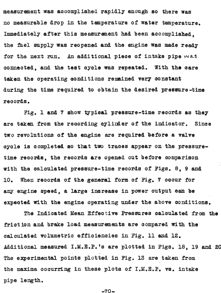
The pressure in the pipe at any instant may be derived
from the solution of the equation of motion. A comparison
of the calculated and the experimentally determined
pressures is made in Fig. 8. The pressure is in pounds per
square inch and the time is measured along the abscissa in terms of the engine crank angle. The engine speed is
1220 revolutions per minute. The pressure variation is shown
-8-Lii a. a: L F-QD LJ -J D -J
Z e
Za U< eto 0 e N N -(~~~~~i io a. -CD 0a LUI-6
I u a0 a .o O Li I -J U 2 U In AK rGi n'-over one valve cycle which requires two complete revolutions
of the engine before completion. The valve is open from the
dotted line marked "o" to the dotted line marked "C". The
frequency of the pipe is five times the frequency of the
valves in the first set of curves, four times the valve frequency
in the second and three times the valve frequency in the
third,
Fig. 9 shows the comparison of the pressure time
records for an engine speed of 1630 revolutions per minate
corresponding to those of Fig. 8.
The first set of ourves in Fig. 10 shows the
comparison of the calculated and observed pressures in the
valve port for a pipe whose frequency is approximately 3.6
that of the valve frequency. The engine speed is 1220
revolutions per minute. The second set is a comparison of
the records when the pipe frequency is twice that of the
valves and the engine speed is 1630 r.p.m. The flattening of
the experimental curve indicates that the amplitude of
the pressure waves are so great that the assumptions made in
the development of the theory of sound no longer hold.
The power output of the engine is of primary importance.
Some function is desired which will indicate Just how the
output will vary for different engine speeds and lengths of
intake pipe. The lumetrio efficiency, which is defined as
the ratio of the volume of air actually swept into the engine
per cycle, reckoned at the temperature and pressure of the
I-0
a. i--J ~Cz
z
Z0
C r-c/) LJ X U') Lii ra Q.VI z: 04 H 0C hO
0OC
H H IS I, _t
o '- 4 p I 1 pI UII&0
O i-i0
tfl r-i O0
H P o C o : H 04 ' . H 0 0 O C Er.. Ci0
0
0
0
0
0
Io CQ CD-00
:
p
w H E-4 i DaL *-U W4 00c 0-4o
P4O H 4tPE.r
Uo
I-I . rs O ~~~~~~~~~e~*' W F3Pc~~ z r4H O 0 0 00 0 H °<
*
o~~~~~~~~~~~~~~~~P
Pe~~
,
~ ~
---
~
0
i-40
to '-o I-W X o w .w~ C.) I-.' rzlH W P; A4 H 04 0OO.
O CV H CiD E-O fi COO O O0 Ie O '0
CM0
0
0
0
0
0
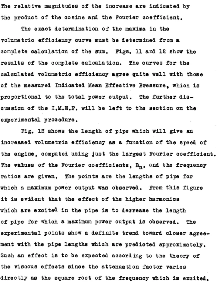
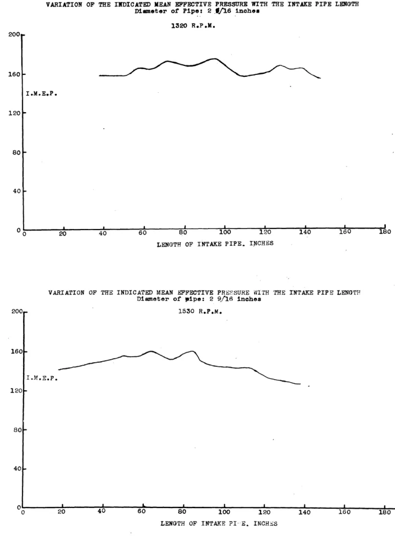
o0 O O NV O2 r-i r-IOPTIMUM INTAKE PIPE LENGTH FOR VARIOUS ENGINE SPEEDS
Pipe Diameter - 2 9/16 inches
Calculated Experimental * =P- 3' Bx 3 .255 f =a 5 f5 B5= 043 2200 140 120 100 80 LENGTH OF INTAKE PIPE INCHES 60 40 20 0 800 1000 1200 1400 1600 1800 2000 ENGINE SPEED R. P. M. Fig. 13
fWf,
the simplified theory given earlier. The solid lines of
Fig. 13 indicate
the best length
of intake
pipe
for
different engine speeds as predicted by the simple sound
theory. The three
curves
are for the ases when thefundamental pipe frequency is three, four or five times
the frequency of the valve mechanism respectively.
The
points indicate the best lengths of intake pipe as determined
from experiment. It is to he particularly noticed that as
the engine speed becomes greater the experimental points
tend to approach more and more closely the curve determined
from the simple theory.
The treatment of the viscous effects
occurring in the pipe predicts that such an approach is to
be expected. The frequencies excited in the pipe which
are higher than the fundamental suffer a greater attenuation.
Then the valve frequency becomes high, the components made up
of the higher harmonics are almost completely damped out,
The coefficient of the predominant term of the Fourier series
is given with each curve, and indioates the relative amount
of supercharging.
Comparison of Figs. 11, 12 and 13 indicates
that the
effect of the higher harmonics which are exoited
in
the
pipe
by the pressure pulse is to shorten the length of pipe at
which maximum supercharging will occur as predicted by the
simple theory.
-11-The general theory clearly indicates that the length
of pipe for which. the maximum supercharge will occur may be
varied to some extent by varying the valve timing.
Physically, this means that the velocity-time record at the
intake port will be hanged by the hange in valve timing. The very good agreement of the general form of the calculated and the observed pressure-time records an of the calculated volumetria efficiency and the observed I.&.E.P. indicates that over the range of speeds studied the theory of sound adequately escribes the phenomena
taking plaoe in the intake pipe. The length of pipe for the best supercharging may be predicted as accurately as
desired provided the attenuation factor of the intake
pipe, the velocity of sound in the pipe and the variation
of the air velocity in the intake port is known. The
air velocity in the intake port is determined by the valve timing, the residual pressure in the cylinder when the valve opens, and the piston velocity and the frictional
resistance of the intake port. The simple sound theory is
certainly sufficient for any usual design problem which might arise.
The previous investigations of the intake pipe problem
certainly show that the phenomena
occurring in the intake
(1)
pipe were not at all well understood. List alone
(1
) ~i$
-Inreas'ng the Volumetric
Efficie&ny
of Diesel
ng nes-N.A... Tec hnical Memo. No. 700
12-recognizes that the air velocity in the intake port plays
an important part in the generation of the vibrations in the intake pipe. His work does not consider the effect of the valves. The lack of understanding is most clearly shown in the methods of attack on the experimental problem. In the first place, previous investigators have not recognized that the peaks in the power output occur over a relatively short range of intake pipe length. The broadest peaks which oecur for the longer lengths of pipe are within a range of eight or ten inches of pipe length. Thus a change of length
of one foot will completely miss a power peak, and will miss more than one peak when the pipe length is short.
These investigations have stopped at lengths of intake pipe which are certainly much shorter than those for which
the greatest maxima in power output occur.
While the volumetric efficiency is the most easily
calculated quantity, it is not the most easily and accurately measured one on account of the difficulty of metering the air flowing into the engine. For this reason any measure-ments of volumetric efficiency are unreliable. The total power output or the I.M.E.P. which is directly proportional
to the power output is the best measure of the air forced
into the cylinder per stroke, provided the fuel air ratio is correct for best combustion.
Dennison(l) and List state that the best results were
gotten for smaller diameter pipes. This is true, as far
as their investigations went. However, their experiments
stopped at relatively short lengths of pipe. In the
narrower tubes the velocity of sound is reduced and the
resonant pipe length is shorter than for the larger diameter
pipe. Evidently, in their experiments they approached more
closely a resonance peak for the smaller diameter pipe. It
is ertainly to be expected that if they had carried their
investigations through for longer lengths of pipe, they
would have bund the larger diameter pipe giving the greatest effect at resonance.
In the following pages the general theory of the
forced waves will be eveloped, and the statements made
above will be justified.
-14-II. THE WAVE EQUATION
The discussion of the intake pipe problem of the internal
combustion engine requires a knowledge of the fundamental
principles of the dynamics of fluid flow. These principles
are incorporated in the equation of continuity and the
hydrodynamiaal equations of motion. A complete derivation
of these two equations is given in Lamb's Hydrodynamics,
Chapter I. The equation of continuity describes the mass
flor of fluid through a space element in the fluid. It is
expressed mathematically as:
1)
245+
Tt,
+
+ Fe
f
is the density of the fluid, and u, v, and w
are
the
components of velocity of the fluid along the x, y, and
z
axes,
respectively.
The equations of motion which
describe the forces acting on the element of fluid are:
-7~.+
V=
I
I
'
_
I the i
t
usion of the behaviour of
y
hk
a
comp ressible
+ IAk + V + ZiP=
z-p' is the pressure in the fluid and X Y, and Z are thecomponents of the external forces acting on the fluid
element.
In the discussion of the behaviour of a compressible
fluid it is customary to introduce the condensation, s,
which is defined as the fractional change in the density
-15-of the fluid. The change in the density is due to the
forces which are acting on the fluid. The equilibrium
density and the instantaneous density are then related by
the equation,
3) , p/¢1( + ).
This expression is introduced into the equation of
continuity which becomes
-f +t s)CA.
V
++
++0 + .The assumption is made that the condensation and the
products of the condensation and the pace rates of
change of the velocity components are small compared
to unity. The equation of continuity reduces to
4)
t
4.+
ax
a.,-
(y
+
+
=
o
Then the asasption is made that the velocities may be
derived from a velocity potential, . The velocities in
terms of the velocity potential are then
5) U --
;
;
W, 's
This last assumption reduces the equation of continuity to
the form:
6)
at az
+
+s+
=
-16-In their general form the equations of motion are
difficult to integrate. In the theory of sound the assumption
is made that the product of the velocities and their space
rates of hange are small and can be neglected in comparison
with the other terms of the equations. The simplified
equations of motion are
7)
-These equations are multiplied by d, dy and dz, and summed,
The result is a total derivative,
8)
dEjf-]
-d
p p;
if the external forces an be derived from a potential
function, W.
-Wi
=
Id
+
Ydy
+
Zdz.
The omponents of the force are then:
w
8i
Ei
WShen equation (8) is integrated, it becomes
9) - (0 = w -
Y
+ P' -PoThe density variation has been previously assumed to
be small and so has been onsidered as a constant in
-this integration. The zero subscripts refer to the equilibrium state of the fluid. When the main interest
is in the variation of the quantities from equilibrium, the equilibrium values may be set equal to zero.
The compression and the expansion occur rapidly enough so that very little heat transfer takes place.
The fluid is assumed to obey the adiabatic gas law.,
10)
P
=const,
& is the ratio of the specifia heats of the gas at onstant pressure and at constant volume. To a first approximation the small excess pressures may be derived from the gas law by
differentiation.
11)
£C
.!
=
The quotient, p't , may be written
P_
X
s_1
t
24
r
1-
_
a
_
*
d
P
The sum of the last terms in the bracket -is small an may be safely beglected. Equation (11) then becomes
=
/-
=
02
constant.
The condensation is ust
o
80 that the excess pressure,p, may be written as
12) p =p' = s
The equation of continuity then reduces from the form (9) to
(9a)
4cI
JP it
+This latter form of the equation of ontinuity is substituted into the equation of motion, (6), to give the general wave equation:
13) a2 yp"
a2m
V
2
When no forces are acting except those due to a
pressure gradient, this last equation reduces to the
ordinary wave equation.
14)
1WV- .29
The main interest in this discussion is the case for
plane waves. The solution of the equation for the case
of plane waves,
15)
1 t b)~~~~~~~~~~? 4
~'
L'-6
t .
is achieved by the introduction of the arbitrary
trans-formation, due to D'Alembert,
xI + a,t ; =x + &2t
a, and a& are arbitrarily selected constants. Upon making
the transformation the various partial derivatives
become:
T-
5
i
t
t
am +
2
'
a + a
.
2 a,Z.e ,qui + m i t0
The equation of motion then assumes the form
-19-°
2)'
C
s
a
a)
+
2ala
2O
a
. ..
As a and a2 are arbitrary constants, they an be selected
as the roots of the arbitrary equation
(a
2-
2)
-
0.
In this ease a = ; and a2 -, and the differential
equation that iaust be solved is
Its solution is simply
16) (p. P(xl) + (x2) - (x +
ot)
+ G(x t)which is the familiar expression for the velocity potential
of a wave propagated with the phase velocity e. F escribes
the wave traveling in the negative direction, and G the
wave in the positive direction.
The velocity has been assumed to obey the relation
The sinusoidal solution which satisfies the: equation is
17)
ike-
ik(ct - x) +Be
-k(t
+
x)
in
whioh
= CO/ =
If/
0
zA
f is the frequency of the waveand is its wavelength. The
velocity u is then
-
-
[
ik
x
-
ikx]c-iwt
Integration of the equation of motion gives the expression
for the total pressure, p'* a I
..
~ ~
/ a x
-20-p, . k Af[reikx _ Be-ikx] -iWut dx
The excess pressure, p p' -p, = is immediately obtained
on the integration of this last equation.
18) p -i o
o[AeikX +
Be
ik
'x]
ei(t
This last expression is Just the
produot
of
the
density
and the time derivative of the velocity potential.
19)
p
iPWIF P. o cLS,
The displacement from equilibrium,
y, is
20) y
AU&ikx B-ikl-iwt
The space rate of variation of the displaeement is then just
21)
i"i
*k
ikx + Be-ik
3
i!t, iW
By oomparing this equation with (19) it is immediately
seen that the ondensation is
22)
S=
-.
ax
In general this relation holds for the solution of any
equation whose solution ean be put, in the form of
equation (20).
This general theory holds for the simplified picture
of the intake pipe phenomena. The effects of visoosity and
various forms of dissipation must be considered in order to
get a qantitative view of the subject. These effeets are
dealt with in the next seeation.
-21-III. THE EFECT OF VISCOSITY
The intake pipe of an internal combustion engine is
often quite long and of quite small diameter. On this
account the pressure waves occurring in the pipe suffer
oonsiderable attenuation. The attenuation is not due entirely to the viscosity of the air alone, but energy
is also dissipated by the vibrations iueed in the walls
of the pipe and from the open end. The diameter of the
pipe is usually quite large enough so the conduction of heat has little effect on the waves. The problem of heat
conduction is thdaoughly treated by Lord Rayleigh.
The dissipation of energy due to vibrations set up in the walls of the intake pipe becomes more and more marked the thinner the tube walls and the greater the
amplitude of the pressure waves. The mathematical
treatment of these losses becomes so involved, especially
for a jointed pipe, that itvill not be treated in this
discussion.
The analytioal treatment of the effect of viscosity
was originally carried out by Kirchoff, and his results
have been hecked very closely in experimental investigations
in which suitable precautions were taken to prevent any
losses ue to the pipe itself. This treatment indicates
how the effects of mechanical losses influence the
vibrations and will be carried out in detail.
(1) Rayleigh - Theory of Sound, Vol. II.
-22-Viscosity has its greatest effects in the
neighbor-hood of the walls of the tube. An estimate of the
thick-ness of the fluid layer in which the major part of the effect
will be observed can be made by the following analysis.
A plane is assumed to have an oscillating motion relative
to the fluid. Its velocity is u, and it has an angular
frequency . An element of the plane has an area (didz).
y
L
ii~~~~~~~~~~~~~~~~~~~~~~~~~~~~~~~~
The forces acting upon an element of fluid of
thick-ness, dx, to the wall are those of inertia and viscosity.
The inertia force is simply
1)
u xdyds
If the
coeffioient
of viscosity isma., the viscous force at the wall, x = O, isOn a plane a distance dx out in the fluid, the viscous force is
£=0
-23-i I i Iso the resultant force due to viscosity is
3)
- t-E W74 d$ JThe coefficient of viscosity is assumed to be a oonstant so the equation of motion becomes
4 )
ar,A
-H2
As the iscussion is about a plane having a frequenay
of oscillation w relative to the fluid, the solution of
the equation of motion is assumed to be
-i(wt -
k'x)
5) u Ae
When this is substituted into the differential equation,
an expression involving the constants of the system and
k' results.
-ilOU
W-U
-
jTk
From
the
theory of
complex
variables it is
known
that
so that k'
redues
to the form
6) k' -
+
( + ) +b (1 + i)b =
The solution of the equation of motion is then
7) W(,/= Ae- i [w t+ b(l + i)x]
-24-This solution describes a damped velocity wave travelling
normally to the wall. The expression for a wave travelling
outwardly from the wall is
8) U (x) = Ae-bxe -i(wt - bx)
Now let b
. 2:/A
. Then at a distanceA
from the plane the velocity has reduced to e2 0 1/540 th of its value at the plane. The value ofA
can be easily alculated from the relationThe ratioo,f, is the inematie oefficient of viscosity
and is approximately equal to .13 at room temperature and
one atmosphere pressure. If the frequency of oscillation is
f ycles per second, the value of
A/
is aboutAt ten ycles per second. this wavelength is about four
millimeters and reduces to two millimeters at 40 cycles
per second. It may be safely assumed that the effect
of viscosity is negligible over a half centimeter from
the wall. This means that in a tube of over a centimeter
radiua there will be a column down its center in which plane
waves will be propagated with essentially no effects from
the side walls.
-25-The important question is the attenuation of the
wave as it travels the length of the intake pipe. This is developed from the consideration of the forces acting
upon an annular ring of radius r and length d which is
concentric with the tube as shown in the following figure.
y
On the inner surface of the ring the viscous force is
-2zt -a-
ax
The force on the outer surface ia
_2Sfi &
E-Ex
r-ax &rThe resultant retarding viscous force is then
9) 2xe /A( 5 t &xr
The external force X of the hydrodynamical equations of
motion is just the ratio of this force to the mass of
the annular ring of fluid.
-26-i
i
10)
x=-
¢
u
-
)*
.
Thus the hydrodynamical equation of motion becomes
11)
C~ =~
orv
%%
'
'
The pressure gradient is not a function of the radius
of the tube,
and
the velocity is assumed to be an harmonic
function of time.
he
solution of the equation of motion
is
-iot
12)
u
= U
oe I;
-iu
The equation of motion can then be placed in the form
13) -i lo+
+ a
(
u
-1
!r
+r.e
+ k2]
,,
k
2
t
Since the pressure gradient is not a fanction of r, and
the operator is a Bessel's operator of zero'th order, the
solution in terms of r is
14) A + QAJcr)·
The velocity must be finite at the center of the tube
and zero at r
a, the radius of the tube.
Thus
the
constant A is just
The complete solution of the equation in terms of r is then
, p [z ~f.
15) u
=
1This is Crandall' solution of the equation of motion.
The average fluid velocity, u, over the ross section of
the tabe is
16)
U
a
tk
Vk)
a&a2
"(a)
1 a_
El 2 J, (ka)-Ez
a
J[Xz
)
The average velocity depends upon the radius of the tube,
the frequency of the vibrations existing in the tube and
the kinematic coeffioient of vieooeity, , of the fluid.
In the case of a tube having a diameter of five
oenti-meters in which vibrations having a frequency of two ycles
per second exist the magnitude of (ka) for air at
atmospheric pressure and room temperature is approximately
twenty-five. In the intake pipe problem the valme of this
product will always be larger than this. By expansion of
the Bessel's functions (Jahnke and Emnde, page 301) it may
be shown that if the magnitude of their argument is greater
than ten, the ratio of the two functions is just equal
jJ:
=r
-i;
x V-i
a
a-y
-;
X>10.
The average velocity across a large iameter tube is then
17) ui
+u
(l-i)+
since v -i i and4tAk
The last term in the brackets arises from the effect of viscosity. Its influence beoomes less the larger the
diameter of the pipe and the higher the frequency of the vikrations in the pipe.
Equation (12) states that
u -iwu.
at
With this in mind it is seen immediately that (17) is the
differential equation esoribing the average fluid
is-placement ,y, over the ross-seotion of the pipe.
18)
(l+
g
+
O/.
4.ay
In the previous section the excess pressure was in a sound wave shown to be equal to 70o2A · Thus equation (18) reduces to a form in which y is the dependent variable.
19) /Ol (1
+
)at
a
a(:
m
/:
P
S
-
Y
-29-The solution of this equation is
20) y = Aei(mx - ct)
in which
21)
m
-
E(
+
1
j(
+
ia
]
/2
The quantity 1 4 is small. Then if the value of o' is defined as
22)
1 =rr;-l'
2
e(l
_
1-the value of m reduces to
23)
+[T
+
ivik
,
The
complete solution of the wave equation is
24) y
Ae
aO
·
+ Be
e -
'
The phase velocity is ' and it is seen to be less than in
the open air.
Many
investigators
have shown that the
decreases in the phase velooity varies inversely as the
radius of the tube and that the attenuation factor increases
inversely as the radius of the tube. (Rayleigh - Theory of Sound Vol. II - Section 350.)
The effect of heat conduction has been shown to add a
constant to the coefficient of l/aV'w (Rayleigh, Section 350).
-The issipation of energy from the vibrations set up
in the walls of the ointed tube is so complex that no
analytical treatment will be attempted. The assumption
will be made that over the small range of frequencies to be
studied, the attenuation coefficient is practically a
constant, and that the solution of the wave equation an be written as
25)
yAe
5~
.,
t
sa
z
-in(t +
25) y = A
an
t
+Ben
For a given set of conditions this is a perfectly general
expression describing the wave.
Eckhardt, Chrisler, Quayle and Evan ( U. S. Bureau of Standar&s Technologic Papers, Vol. 21, page 163) have
measured the attenuation in voiae tubes of various diameters.
The conditions under which their measurements were made
are very similar to those existing for the engine intake
pipe. They find that the attenuation factor is almost a
constant over a wide range of frequencies. Their results
are used in the calculations which are made later in this
discussion.
-IV. THE ACOUSTIC IMPEDANCE
In the later sections of this discussion the concept
of the acoustic impedance will be found to be most helpfal.
For this reason its development is carried out quite fully
in this section.
A general form of the wave equation is
1)
PjT~+Q
Zri
+
RYm
y
y is the fluid displacement and F is a force whieh is a
harmonic function of time. In general the coefficients P,
, and R are fanotions of the space coordinates. If F is
2)
F - Foit
the equation may be put into the form
3)
i((UP
-)
+
Q]u
since the isplacement may be expressed as y y.e ' i t .
The ratio Z1 of the force to the displacement velocity,
4)
Q +
i
(P- _
,
is a onstant at a given point in space, or if, P,Q, and R
are all constants, Z is onstant everywhere in space. The
motion which is described in equation (1) is fixed
every-where in space if the value of Z is given and the magnitude
of y or u is specified at some particular point.
In the analysis of electrical ircuits the coefficients
P, Q and R are the inductance, resistance and capacitance of
the circuit, respectively. The force is the applied voltage
-32-and u is the current. In this case the ratio Z is
defined as the electrical impedance. If the inductance,
resistance and capacitance are constants, the electrical
impedance is distributed.
As an analogue to the electrical impedanoe the
acoustic impedance is defined as the ratio of the force
acting on the fluid to the fluid velocity. The specific
acoustic impedance Z is defined as the ratio of the excess
pressure to the elocity.
5)
z-x
ui
A is the area over which the force is acting.
In general the force is not a simple single term harmonic
fnction, but more often is described by a sum of terms
having different frequencies. An example is that of a
force described by a Fourier series.
-int
6)
?
-
J X
In this ease there is a displacement velocity, un , for
9,¢h term of the series describing the foroing fanction.
Thus the ratio of the force to the velocity is not a
function of space alone. However, each harmonic term,
Fn, of the series has an associated velocity, un, and the
ratio
7) ~Un
-33-is a fnation of the space coordinates alone. Since the total velocity is the sum of all the component velocities,
8) un =f
-
·
=e
;
Tnhe=o
n=ln
The force may be written
to
9)
-
a
-intwt I-in.at
The pressure isp M
-
2 Un hz n in nm-.034
-V. THE ACOUSTIC IMPEDAENCE OF A PLANE WAVE IN A TUBE.
Each time the intake valves of an internal combustion
engine opens, a plane wave pulse is sent down the tube,
being superimposed upon any vibrations which exist in the
pipe. It is convenient to discuss the phase relations of the velocity due to this pulse and. the pressure by means of
the specific acoustic impedance.
The solution of the equation of motion which describes
a plane pulse traveling the length of the tube is
1)
y
B
-it
- s (u - ib)x
b
; ;bT
The excess pressuare of the wave is
2) p
=
-pc
2 =xpc2(a
-
ib) y
and the fluid velocity is
3) u = -imy.
The specific acoustic impedance for any given frequency is then
ixo
2
(a
-
ib)
4) Z = .
___
The damping coefficient per unit length of the tube ,a, is small and can be neglected. The impedance reduces to
in which is the velocity of sound in the open air, and
c' is the velocity of sound in the tube. The impedance
for a plane wave travelling in one direction along a tube
is real, positive or negative, depending upon whether the
wave travels on the positive or negative direction, and is
almost independent of the frequency of vibration. It is
independent
of the time
and position. Physically,
this
means that if
a
pulse is started
from the valve end of
the intake pipe the pressure and velocity of the pulse
remain
in
phase until a
boundary
is reached.
hether
they
remain
in
phase afterward, depends upon the effect of the
boundary. If the specific aoustic impedance
of the
standing waves in the pipe has the same sign as the impedance
of the pulse, the
standing
waves
will
be maintained, and
resonance will exist in the intake pipe.
The next step in the analysis is to investigate the
acoustic impedance of a pipe open at one end, and discover
whether
a resonance
condition
oan exist.
a-VI. SPECIFIC ACOUSTIC IPEDANCE IN A TUBE WITH AN OPEIT END.
The specific acoustic impedance of waves in a finite
length of tube is complicated by the reflections from the
ends~. An engine intake pipe is open to the atmosphere, so
the impedance of a tube open at one end will be derived.
A simple diagram of the tube is shown in the figure. _
x 0
x=L
The impedance will be derived for any point x along the tube.
The open end is at L.
Since pressure waves are reflected from the end of the
tube the general solution of the equation of motion mst be
utilized to derive the impedance. The general solution is:
(ex(a
-
ib)x
-r(a
-
ib)x
-ist
1) ;5 * (+e +) Be .)
At an open end the pressure is always that of the
surrounding atmosphere so there i no excess pressure. Since
the excess pressure is directly proportional to the space rate
of change of the isplaaement,
2) ( )
(a - ib)
(As
(a -
ib)L -(a
-
ib)L
2)
(qo
(B
ib)
(
-B
e
)
The equation is solved for A.
-36--;,,¢ak
-
!b).
3) A . BeThe displaoement becomes
4) y
As
"x(a
- ib)L x(a - ib)(x - ) -x(a-ib)(xL
-j-it
4tey = Ae + ·eThe braoketed. term is Just twice the hyperbolic cosine so the
displaoement reduces to
y (a - ib)Lit
5)
y
2Ae
oosh
(a
- ib)(x
-
L)e
The pressure at any point in the pipe is
6) p
-'o£S
*
Aea.-
ib)sinh
(a
- ib)*
(x - )
and the velocity is
- (a - b)L
-iwt
7) u =aicAe eosh (a - ib)(x - L)e
The ratio of the pressure to the velocity is the
speoific acoustie impedance for a given frequency.
8)
~Z
- I D -(
-
Ca
- ib)
tanh
x(a - ib)(x -
).
Since a is very small, it may be neglected in the coefficient
of the hyperbolic tangent. From the preceding section xb = w/'
so the impedance reuceas to
9)
Zn
=-
tanh (a -
b)(x -
L).
An investigation of the properties of the hyperbolic
tangent
reveals
that,
when
the product, b(x - L) is negative
an. equal to an oadd, positive half integer, it is real and
negative in sigX. In this case the impedance in the tube
is in phase with the impedance of the plane pulse, and it is
-to be expected that the succession of plane pulses produced
by the valve-piston mechanism of the engine will maintain
standing waves in the induction system.
For very small damping the impedance in the tube
approaches more and more closely the value for the
non-viscous case-.
10) z = -ia tan c (X -i).
THE EPYERBOLIC TANGENT.
The simplest method. of obtaining a particular value of
the hyperbolic tangent for the evaluation of the specific acoustic impedance in the tbe is a graphical one. The
hyperbolic tangent is expanded into its real and imaginary
parts, designated as X an& Y, respectively. These expressions
may be solved for the arguments of the hyperbolic tangent,
and the results for constant values of the argument are
plotted as funotions of X and Y which are onsidered as
ordinary Cartesian coordinates.
The hyperbolic tangent is first written
1) tanh (a-ib)(x-L) tanh x(oM-iJ) - +
iY
k-
(x
-
L);P
b(x
-
L).
The function is expanded by means of trigonometric identities.
2) tslh (cA-mi(3) - -i sin (3+ i cos (3.-id)
cos
=+
'sxa
(os
·
-38-a)lU
k 0
1---
y
in
3) 1 ...
-
--
-...
aosh 2bo+ o /3 osh 2a+ os
2x/
When is eliminated from these expressions, is
reduced to the funttion of X and Y.
4)
coth
2U:
02
_
+
This is just the equation of a irole with a radius equal
to the each 2B(with its center lying on the axis a distance from the origin equal to oth 2xE.
5)
(X -
oth
2x
0()
2+
2
= oah
22d.'
When Okis eliminated from equation (3), is expressed by the relation
6)
cot
2/ 3 -_tX__- .2y
whioh is the equation of the ircle 7) 1 + (Y - cot 2 2 - 02 2:f
This circle has a radius equal to the aose 2x, and. its center
lies on the Y axis at a distance equal from the origin to
cot
2x
p.
These circles have been plotted in Figs. 14 and 15.
The values of3 have been indicated where the associated circles cut the Y axis, The values of dare indicated on the proper ircles. The magnituie, /i, is measured from
the origin to the interseotion of the two oirles which are assooiated with the desired values of Ok and/,3. The
phase angle, ~n, is the angle between the real axis and the
measured line. This angle is ero for half integral values
of73.
fPn
is positive for values of/3between n and (n +),
-39-ACOUSTIC IMPEDANCE OF F TUBE c -Th . -(- -ICI e- 'C "C-LC IN INCHFS
r
e I1 idACOUS TIC IMPEDANCE O A TUB - T.., ,,r ( -. n ) ' " 1 ' l scaLf Io INCHEt FIG. 15 r .1 C I i1 IJi
i
-~I~. I - g rn being a positive interger varying from zero to infinity
(Ptis
negative
when has
a value between n + 1
and (n
+
1).
The maximum
values of the hyperbolic tangent are seen
to occur when the phase angle is
zero
and
8) b(x-1)
(X-I
=
--
,; n
1, 2, , 4, 5, ---.
The method of measurement is clearly shown in Fig. 15.
-40-VII. TRANSMISSION.
1. Change in phase at a onstriction.
When the intake valves are open during the suction
stroke of the engine, a plane wave pulse is sent through
the valve opening, In general the area of the valve opening
is considerably less than the area of the intake pipe. The
friction in the valve port is quite large, an& the pressure
on the intake pipe side of the valve can be expected to lag
the pressure ust within the cylinder. The following
cis-oussion shows that the lag is too small to be deteted,
although the hange in magnitude of the pressure across
the port may be appreciable.
The pressure pulse is traveling in the direction
indicated by the arrow in the acompanying figure. The
area of the cylinder cross-section is Sl; the effective
area of the valve opening is 2; and the area of the intake pipe ross-section is S3. The effective length of the valve constrition is 1.
The incident and the reflected displaeements in the cylinder are
1)
y k
. Ale
-i(tt
- klx)
and
1)
-imt
+
lx)
1
2)
Jr
=Ble
B
;
=-respectively. In the constriction the isplacements are
-i(Wt -
)
-i(Ot
+
kx)
3) A e and B2
respectively.
The pulse whiah emerges into the intake pipe and serves to
build up the tanding waves is described by the relation
~4
Ae i[wt - kl(x -
L)]
In each case the oefficients of the exponentials are complex
functions. The problem is to express the amplitude of the
pulse within the cylinder which is incident upon the valve
in terms of the amplitude of the emergent pulse an& the
dimensions of the system.
The pressure must be continuous across each Joint, and
the equation of continuity must be satisfied. The following
four relations express the satisfaction of these conditions
in terms of the complex amplitudes and the dimensions.
5)
Al- Bl
A2- B
2at x= 0
.
ikL -ikL )
2.,
20
25~at
'B
x = L.
S2 (A2eik+
B2e i k=
)S3A3
The ratios S1/S2 and S2/S3, are set equal to m and n. In terms of the amplitudes of the waves in the constriction the
amplitude of the incident wave in the cylinder is
7)k
- f
(m+l)A
+1(m1
B
an& the amplituaes of the waves in the constriotion are
expressed in terms of the amplitude of the pulse emerging
from the constriction into the intake pipe.
8)
A
2-'
Ln1eiikL'
'
2
(nij
ikLA
Equations 7 and 8 are solved for the amplitude of the wave
in the cylinder in terms of the emergent pulse.
9) A
=
(m+l)(n+l)e
_3k
ikL
+
(m-l)(n-l)eikl]
=
A3Emn+l)
coo k -i(m+n) sin kL]*The phase angle , of the coefficient of A3 is Just
10)
Q
=
tin.
-
+n
t
U-)
;
k-
.
v
The effective length of the valve constriction is but a few centimeters in most engines, and the ratio of the angular
frequency of the engine to the velocity of sound ', in the
constriction will be quite small if the valve opening is
sufficiently large that Kirchoff's equation of otion will
hold. n this ase the phase lag of the pulse in the intake
pipe is very small and can be neglected. No deteetible phase
lag was found on pressure-time records taken simultaneously
within the cylinder and in the valve port. A measurable drop in pressure across the port was, however, found.
-43-2. The Effect of a Small Volume at the End of a Pipe.
The dimensions of the cylinder of an internal
combustion engine are small compared to the dimensions of
the intake pipe for which supercharging effects are obtained.
The analysis is considerably simplified if the effect of the
cylinder volume can be neglected. This section presents te
Justification for such an assumption.
A simplified iagram of the piston-oylinder-intake pipe
system is shown in the accompanying figure. The cylinder area
is 1 and the intake pipe area is 2 . The position of the piston
when the crank is turned 90° from top center is at x = - b. The valve port is at x = 0, and. the open end of the intake pipe at
X:= a.
x=-b
x=O
x=a
,The displacement within the cylinder is
l)
Y2
-A2e i(wt
-k)
+
B
e-i(t
+
Bx)
-and that in the intake pipe is
-i(oat
-
kx)
-i(ot
+ kx)
2)
'
Ale
-i(t
-kx)
+Ble
At the open end of the pipe there is no excess pressure, and the amplitudes of the displacements in the pipe must
satisfy the relation
-44-I
I
3) (
z ,a
k(e
, B1
)
=
o.
3)
U )
-
(eika
-ika
Thus
-ika
i00t
4)
yj W 2A
coao k(x
)e it
The air follows the motion of the piston so at x = -b, the
air displacement is equal to the piston isplacement.
ib -iJkh
5) A A2 ikb + B2e
A is the amplitude of the piston displacement.
Across the joint at x = 0 the pressure must be
continuous and the equation of continuity must be satisfied.
These conditions produce the two relations
'
6)
2sli
0co8
ka
= 2k
+32)
=8
1A 0o8
,ai&
-ikI
7)
-2A
sin ka
-
A2
B
-A4 s
The amplitudes of the displacement within the cylinder
are
then
8) A2
-
A m _ a _t,2
B2
Ta
-2Jt+
54IS
;
m.
s
22582
These coefficients are substituted in equation (5) which is
then solved for the coefficient A1.
1