Digital Material Aerospace Structures
ARCHNES
MASSACHUSETTS INSTITUTEby
OF TECHNOLOGYBenjamin Jenett
DEC
0
9 2015
B. Arch, U.C. Berkeley, 2008
LIBRARIES
Submitted to the Department of Civil and Environmental Engineering
in partial fulfillment of the requirements for the degree of
MASTER OF SCIENCE IN CIVIL AND ENVIRONMENTAL ENGINEERING
AT THE
MASSACHUSETTS INSTITUTE OF TECHNOLOGY
SEPTEMBER 2015
2015 Massachusetts Institute of Technology. All rights reserved.
Author:
Signature redacted
Departn
of CivK anInvironmental Engineering
August 7, 2015
Certified by:
Signature redacted
Caitlin T. Mueller
Assistant Professor of Architecture
Thesis Supervisor
Signature redacted
Accepted by:
I
1
7
eidiNepf
Donald and Martha Harleman Professor of Civil and Environmental E gineering
Chair, Graduate Program committee
Digital Material Aerospace Structures
by
Benjamin Jenett
Submitted to the Department of Civil and Environmental Engineering on August 7, 2015 in partial fulfillment of the requirements for the degree of Master of Science in Civil and Environmental
Engineering at the Massachusetts institute of Technology
Abstract
This thesis explores the design, fabrication, and performance of digital materials in aerospace structures in three areas: (1) a morphing wing design that adjusts its form to respond to different behavioral
requirements; (2) an automated assembly method for truss column structures; and (3) an analysis of the payload and structural performance requirements of space structure elements made from digital materials. Aerospace structures are among the most difficult to design, engineer, and manufacture. Digital materials
are discrete building block parts, reversibly joined, with a discrete set of positions and orientations. Aerospace structures built from digital materials have high performance characteristics that can surpass current technology, while also offering potential for analysis simplification and assembly automation. First, this thesis presents a novel approach for the design, analysis, and manufacturing of composite aerostructures through the use of digital materials. This approach can be used to create morphing wing structures with customizable structural properties, and the simplified composite fabrication strategy results in rapid manufacturing time with future potential for automation. The presented approach combines aircraft structure with morphing technology to accomplish tuned global deformation with a single degree of freedom actuator. Guidelines are proposed to design a digital material morphing wing, a prototype is manufactured and assembled, and preliminary experimental wind tunnel testing is conducted. Seconds, automatic deployment of structures has been a focus of much academic and industrial work on infrastructure applications and robotics in general. This thesis presents a robotic truss assembler designed for space applications - the Space Robot Universal Truss System (SpRoUTS) -that reversibly assembles a truss column from a feedstock of flat-packed components, by folding the sides of each component up and locking onto the assembled structure. The thesis describes the design and implementation of the robot and shows that an assembled truss compares favorably with prior truss deployment systems.
Thirds, space structures are limited by launch shroud mass and volume constraints. Digital material space structures can be reversibly assembled on orbit by autonomous relative robots using discrete, incremental parts. This will enable the on-orbit assembly of larger space structures than currently possible. The engineering of these structures, from macro scale to discrete part scale, is presented. Comparison with traditional structural elements is shown and favorable mechanical performance as well as the ability to efficiently transport the material in a medium to heavy launch vehicle.
In summary, this thesis contributes the methodology and evaluation of novel applications of digital materials in aerospace structures.
Thesis Supervisor: Caitlin T. Mueller Title: Assistant Professor of Architecture
Acknowledgements
This thesis and my next steps at MIT would not be possible without a lot of people.
First, I would like to thank Neil for giving me the opportunity to be a part of the Center for Bits and Atoms. There is no other place like it in the world. It is a secret ninja club and I am fortunate to be there. To Kenny, thank you for helping me accomplish my goals, and for leading the way. I should also thank Congressional Republicans for shutting the government down back in 2013; otherwise we would have never met. Thanks to you, I have fallen in love with NASA.
To Caitlin, thank you for believing in me, and for guiding me through the rocky terrain of MIT.
To Matt, Will, Sam, Nadya, and Amanda, thank you for being inspiring lab mates, for putting up with my disco, and for constantly teaching me new things.
To Jaime, Ryan, Joe, John, and Tom, thank you for making CBA such a pleasure to work in. To Leon, D-Bone, and Marwan, thanks for helping me get through that first year of grad school. To the two Johns, thank you for helping me get on my feet at MIT.
To Daniel, thank you for teaching me electronics and for making me feel older and wiser.
To Matt, thank you for taking a chance on me, for covering for me while I learned engineering (still learning), and most importantly, for the Miata.
To Gaston, thank you for inspiring me to build, and for converting me to IPA.
To my Family, thank you for the constant support, for google chats, for fume bro cookouts, and for (arguably) good genes.
To Angelica, thank you for being my co-pilot through all of this. Till death do we part! (kidding) And to Lola, the best dog in the world, thank you for the puppy kisses. I dedicate this thesis to your memory.
Work in thesis was supported by the NASA Space Technology Research Fellowship (NSTRF) and by the
Table of Contents
Table of Contents ... 7
1 Introduction ... 9
1. 1. Digital M aterials ... 10
Lattice Geom etry ... I I M aterial ... I I M anufacturing ... 12
2. Digital M aterial Aero Structures ... 15
2.1 Background ... 15
M orphing W ing Structures ... 15
Twisting W ing Structures ... 16
Lattice Structures ... 17
M orphing Lattice Structures ... 18
Aerostructure M anufacturing ... 18
2.2 Digital M aterial M orphing W ing ... 19
2.2.1 M ethod ... 20 D e sig n ... 2 1 M anufacturing ... 21 2.2.2 Results ... 22 Platform Design ... 22 Platform Components ... 23 M anufacturing ... 25 Assembly ... 27 Actuation ... 28
Flight Perform ance ... 29
2.2.3 Sum m ary and Further Research ... 31
3. Digital M aterial Space Structures ... 33
3.1 Background ... 33
Space applications ... 33
Transportation Considerations ... 34
Construction approaches ... 35
3.2 Space Robot Universal Truss System (SpRoUTS) ... 40
3.2.1 M ethod ... 41
Packing Effi ciency ... 41
3 .2 .2 R esu lts ... 4 2 U n it D esign ... 4 2 Platform Design ... 43 Platform Components ... 44 M anufacturing ... 47 Structural Performance ... 48 Robotic Performance ... 51 3.2.3 Further Research ... 52
3.3 Kilometer Space Array (KSA) ... 54
3 .3 .1 M eth od ... 5 5 D esign ... 5 5 Constraints ... 55 Objective Functions ... 55 Design Variables ... 55 3 .3 .2 R esults ... 5 6 Nylon Prototype Column Design ... 56
Km Structure Column Design ... 59
Transportation ... 62
2.2.3Summ ary and Further Research ... 64
4. Conclusions ... 69
1. Introduction
The work presented here has emerged from a growing body of research based around the concept of
digital materials- modular parts, with embedded function, which are reversibly assembled through a
discrete set of positions and orientations into larger functional structures (Figure 1). These structures have been shown to have a number of benefits. When built from high modulus, or stiff, material (ie: fiber composites), in a specific configuration, they result in what is known as a cellular solid, or in this case, a
digital cellular solid (1). This structure behaves as an isotropic material, with a relative modulus that
scales with the relative density, at varying constants (1, 1.5, 2...) based on the geometric configuration. They also have unique properties based on their discrete nature. One of these is they behave in a
predictable way that allows the analysis of their assembled structures to be simplified. Rather than using computationally intensive methods such as fully meshed Finite Element Analysis (FEA), the structure can be simplified, even abstracted hierarchically, to nafve beam-bending models. This shortens simulation time and complexity, which has significant impact for large structures (2). The parts themselves can be functional; resulting in multi-functional assemblies, such as conducting and insulating electronic parts to build discretely assembled electrical networks (3). Lastly, their discrete, periodic assembly lends itself to automation, enabling large structures to be built with relative robotic assemblers (4). This is critical to compete with state of the art manufacturing, and to advance past the lab and into industry.
Due to these benefits, and many others which will be presented here, digital materials are appealing for many aerospace applications. The aerospace industry- here combining both air and space- has some of the strictest requirements of materials, structures, and manufacturing processes. Here digital materials can
demonstrate not only an ability to compete with state of the art, but also to achieve performance that is not possible with legacy technologies- for numerous reasons, which will be explicated throughout this thesis.
The applications are divided into air and space. Air applications include morphing wing structures. Space applications include reconfigurable truss structures and kilometer-scale arrays. In the following chapters, each of these three applications will be presented and evaluated with respect to numerous aspects of the practical realization of these structures: numerical analysis and simulation, manufacturing and
prototyping, and full scale implementation and automation, among others.
These applications will be presented in the context of the lineage of similar structures before it, as well as the state of the art of competing approaches. The arguments in favor of digital materials will be presented quantitatively and qualitatively, with large and small scale considerations as a realistic technology for future infusion into the aerospace industry. Challenges in doing so will also be presented. Long-term goals and immediate next steps will be presented.
Figure 1: Digital Material Structures (L to R): Extra Small, Small, Medium. Large, Extra Large
1.1.
Digital Materials
Digital Materials are a discrete set of parts, reversibly joined, with a discrete set of relative positions and orientations. This results in novel properties: 1) High performance material parts, linked into specific geometry, can attain mechanical properties that were previously unreachable. 2) Precision comes from the structure itself. Elastic averaging makes these structures more precise than the assembly machines. 3) Functionality is assembled at a constant cost of complexity. Within this framework, one can optimize designs for goals such as strength, weight, or cost. 4) Discrete properties lead to hierarchical
decomposition in modeling and analysis. Important considerations for Digital Material lattice structures are lattice geometry, material, and manufacturing process.
Lattice Geometry
The global behavior of the periodic lattice is influenced by the lattice geometry, which is governed by
stability and connectivity. Stability can most easily be understood in 2D, as shown below (Figure 2). One
configuration is a mechanism under loading, and the other is a stable structure. In order for the mechanism to withstand load, the joints must transfer moment, and the struts bend. This results in
bending-dominated behavior. The other transfers forces axially, and thus has stretch-dominated behavior.
This can be expressed via Maxwell's stability criterion, which for a frame with b struts andj joints, is in
2D and 3D, respectively: M = b -2j +3; and M = b - 3j + 6. If M<O, the frame is a mechanism. If M>O, it
is over-constrained. If M=O, the frame is statically and kinematically determinate. Stretch dominated structures are exceptionally stiff and strong for a given mass, bending dominated structures are compliant, and although not strong, can absorb large amounts of energy (5).
(a) (b)
(c) (d) (e)
Figure 2: (L) a) Unstable 2D Mechanism, b) Stable 2D Structure, c-d) Stretch Dominated 3D Structures, e) Bending Dominated
3D Structuire (R) Colored pairs of co-axial elements result in 4 DOF constrained for 8 struts.
With 3D periodic lattices, another critical property is connectivity (Z) -understood roughly as the number of struts at a node. As explained in (6), the necessary and sufficient condition for full rigidity of 3D frameworks is that the connectivity Z = 12. If a 3D framework has Z = c< 12, then the framework has
(6-c/2) independent mechanisms, and can be partially or fully bending dominated. This can also be
understood by attempting to constrain the 6 degrees of freedom (DOF) at each node with a strut. Two
co-axial struts can only constrain 1 DOF, and thus are counted as 1 Z (Figure 2).
Material
The constituent material from which the lattice is made is used as the "starting point" for determining various mechanical properties of the lattice (ie: stiffness). Then, based on the lattice configuration, a linear relationship can be determined between E and p, such that the final stiffness can be determined. In manipulating these parameters, and thus global behavior, one can essentially design new meta-materials. This is an approach described as a way to occupy previously unattainable areas in material science- such as ultralight regimes space (7). Figure 3 is a chart showing this new area. If a stretch
dominated lattice configuration is employed, from the constituent material, one can follow a line with slope E/p, as the lattice connectivity and thus mechanical behavior ensures a proportional law E/E, oc
p/p,, where the s denotes the respective bulk value of the solid constituent material property. If the lattice is bending dominated, it follows a line with slope E1/2/p. This is less favorable, and is governed
by a proportional law EIE, OC ( p/Ps)2 as connectivity is moved away from stretch-dominated and
towards bending-dominated, it may follow a line with a slope between these two values (Figure 3).
1000
Technical Ceramics CFRP epoxy matrix (isotropic)
-- 0 100 -0 / c> 10 composites E/E
a
(p/p,)CeramicsMtl
E/E WNMetals 77 E/Es C (-/-,-0.1 iE/E, (p/p2 Natural Materials
0.01
--- Foams astomers
100 1000 10000
Density (Kg/M
3)Figure 3: Material Property Scaling based of Lattice Geometry Manufacturing
The proliferation of additive manufacturing (AM) has enabled the production of complex geometries, such as lattice structures. Challenges remain with the anisotropic behavior of some AM methods, such as the popular Fused Deposition Modeling (FDM), whose layer by layer method does not result in isotropic material properties (8). Other methods, such as stereolithography, have more isotropic results, and can lend themselves to the manufacturing of lattice structures. Zheng et al. (9) used projection
micro-stereolithography (additive manufacturing) to create bending and stretch dominated lattice structures with polymers, metals, and ceramics. The largest scale of these specimens was millimeter, and scaled down
three orders of magnitude, while achieving desired linear relationship of EIE, cC p/Ps for stretch
dominated and E/E, C ( p/Ps)2 for bending dominated structures.
Others have made larger scale assemblies of lattice-core sandwich panels using a variety of methods: strip slotting, corrugation, investment casting, sheet perforation and folding, sheet slitting and expanding, winding tubes around a patterned jig, and inserting hollow tubes into laser drilled holes in face sheets (10)
(11). These result in favorable properties, and the applications are focused on primarily sandwich panels.
Another way is discrete lattice assembly (12). In this method, planar elements are linked by shear clips in
3D to form reversibly assembled composite lattices. This assembly is done by hand, but it can scale
infinitely, and can be disassembled and reconfigured into other geometries. This is a distinct advantage, but ultimately will require automation to overcome the throughput limitations of manual assembly. This is the approach taken for Digital Materials.
2. Digital Material Aero Structures
The work presented in this chapter was completed in collaboration with the following people: Kenneth Cheung, Sean Swei, Nhan Nguyen, Daniel Celluci, Nick Cramer, Robert Nakamura (NASA Ames Research Center); Mike Fremaux, Mark Croom, Mia Siochi, Wes Oneal, Clinton Duncan, Lee Pollard, Earl Harris, Sue Grafton, Gary Wainwright (NASA Langley Research Center). Neil Gershenfeld, Sam Calisch, Dick Perdichizzi (MIT/CBA); and was sponsored by the NASA Aeronautics Research Institute.
2.1 Background
Due to the varying objectives of flight regimes and aerodynamic maneuvering and control, discretely controlled flaps are utilized to mitigate sub-optimal wing geometry. This results in additional mass due to actuation, increased cost and complexity due to manufacturing of high performance joints and interfaces, and lower aerodynamic efficiency (lift-to-drag ratio - L/D) due to sharp corners and gaps created by these
discrete control surfaces. Ideally, the wing would be able to adapt its geometry, continuously, to achieve the desired performance- such as reducing drag and increasing stall angle, as well as reducing vibration
and controlling flutter- and to enable new mission objectives. This is the concept behind morphing.
Morphing Wing Structures
Some of the earliest aircrafts morphed: the Wright Flyer I used wing warping to maintain balance while in flight (13). Twenty years later, the Parker Variable Camber wing was designed to change shape (14). However, goals of higher airspeed and increased performance led designers away from flexible structures with undesirable aeroelastic instabilities and load requirements shortfall. With the advent of composite
materials, lightweight and stiff yet flexible designs are now possible with the structural performance to meet flight performance criteria, and focus returned to using aerostructure flexibility for control and performance (Figure 4). Notable projects include the Mission Adaptive Wing (15), the Smart Wing (16), the Mission Adaptive Compliant Wing (17), the Variable Camber Compliant Wing (VCCW), and Active Compliant Trailing Edge ACTE (18). Other approaches look to nature, where birds, insects, and other flying creatures provide design inspiration for projects such as the Nano Hummingbird (19), the Flytech Dragonfly (20), and the Festo Smartbird (21).
Figure 4: Morphing Wings (L to R)- Mission Adaptive Wing (15). Smart fing (16), ACTE (18).
Twisting Wing Structures
Wings have 3 main morphing modes: Out-of-plane transformation, Airfoil profile adjustment, and planform alternation. Within out-of-plane transformation, there can be chord-side bending, span-wise bending, and wing twist. Twist morphing has several benefits over other forms of morphing. It can significantly impact the geometry and behavior of a lifting surface without needing large platform modifications, which differs from variable span or sweep designs requiring complex and heavy
mechanisms. Twisting can provide multiple benefits to aircraft, including stabilization against gust and maneuvering loads, potentially replacing conventional control surfaces, and increasing the lift coefficient.
Wing twisting specifically to improve flight performance and control authority of the aircraft is one of the first forms of morphing (Figure 5). The Wright Brothers used wing twist of a flexible wing for roll control (13). Modern twisting wing structures include the Active Flexible Wing (AFW) concept (22).
Following this was the Active Aeroelastic Wing (AAW) research program (13), and the Variable Stiffness Spar (VSS) Concept (23). Within the domain of twist-based morphing wings, several methods have been developed for desired twisting behavior, through actuation of the internal structure, external structure, or wing tip. Several examples include: external morphing via piezoelectric torque plates (24) or introducing warping deformation of the wing skin (25), internal structure actuation with adaptive shear
beams (26) warp controlled twist using variable torsion and twisting wing section achieved by antagonistic SMA actuation (27). A recurring challenge faced by these morphing aerostructures is the
competing objectives of lightness, stiffness, and shape authority.
_ _W 6DO9fww An
Figure 5: Twisting Wings (L to R) Wright Flyer 1 (13). AFW (22) AA W (13). VSS (23)
Lattice Structures
Lattice structures have historically been used in aerospace structures to achieve combined stiffness and lightness, and come in many forms, such as space frames (28), truss cores (11), and structural frame (29)
(Figure 6); and are appealing for use in aerostructures for several reasons- they are lightweight, space
filling, modular, and tunable, making them candidates for morphing. Geodectic Frames use a continuous diagonal grid of aluminum struts as a 3D truss system- resolving aerodynamic and internal pressure from the external skin into tension and compression (30) . However, due to manufacturing constraints at the time, modifications to aircraft- and therefore geodetic frame - design were problematic (31). Anisogrid structures incorporate composites into lattice form for shells, and demonstrate reliability through structural load path redundancy and anisotropic self-stabilization. Their manufacturing is complicated-requiring custom tooling, semi-automated tow winding, pressurized curing, and destructive experimental testing - due to errors at rib intersections (29). Lattice truss core sandwich structures utilize the weight savings and mechanical properties of a lattice between thin stiff inner and outer skin panels. Metallic lattices are made by investment casting or deformation forming following by bonding/joining). Composite versions are made by machining/cutting, followed by assembly and bonding (10).
IFF
Morphing Lattice Structures
Several projects have investigated morphing lattices (Figure 7), such as a series of honeycomb cells containing inflatable airtight pouches, which modulate the effective stiffness of the honeycomb to allow the trailing edge of the wing to morph (32), a chiral lattice structure, which partially fills an airfoil and uses its auxetic chirality to convert small local actuation into large overall shape morphing and wing tip twisting (33), and an array of compliant cellular trusses with tendons used as active elements to enable continuous stable deformations over large areas of wing shape (34). Other examples of morphing lattices exist with applications to aerospace, such as a periodic octahedral truss column modules with either lead
screws or piezo actuators actuated members (35), a tetrahedral truss plate is backed with an active back-plane, truss elements are replaced with linear actuators, which cause a shape change of the solid yet flexible front face (36), and tetrahedral trusses linked by a specialized rotational node which ensures rotational freedom while linear actuators within the truss affect morphing (37).
(a)
Figure 7: Morphing Lattice Structures (L to R)- Chiral Wing Tip (33), Tendon Active Cells (34), Linear Actuator Truss (37).
Aerostructure Manufacturing
Although many of these approaches demonstrate wing morphing, none address larger issues such as how can next generation aerostructures can satisfy the seemingly orthogonal objectives of flexibility and stiffness, strength and lightness, and achieve these mechanical properties with manufacturing speed while still being a) buildable b) affordable, and c) scalable. The fault may not lie with the design, but with the means to realize the design- the materials and manufacturing processes.
This is indicative of a larger challenge faced in the development of high performance aerostructures: while composites offer desirable properties and can enable new designs, their cost and manufacturing complexity often impede successful prototyping and application. As a whole, the commercial aerospace industry has been moving towards aircraft designs that have fewer but larger monolithic fiber composite parts. This reduces the amount of composite joinery involved, which is both expensive and difficult. However, the logistics for manufacturing these large components (for example, the Boeing 787 Dreamliner is 50% composite by weight, including an all composite fuselage, wings and tail) results in
huge and complex systems tooling and equipment, such as mandrels, gantry systems, tape laying robotic arms, autoclave ovens, and part transportation. This cost delta has been a major hurdle in the widespread use of composite in aerostructures, in spite of their superior performance qualities. (38) (39) (40)
An alternative method to the design, analysis, and manufacturing of aerostructures will now be described, based on the use of digital materials.
2.2 Digital Material Morphing Wing
Figure 8: Early prototype of Digital Material Morphing wing per/brining wing twist
In previous work, by assembling sparse, periodic lattice structures with composite digital materials, high performance digital cellular solids were designed with multiple objectives, including high stiffness, low mass, and energy absorption (12). Recent efforts have focused on assembly automation to compete with
the time-critical manufacturing chain of aerospace structures, resulting in a relative robotic assembler- a small robot that autonomously builds digital material structures and locomotes relative to and within the confines of the digital material structures it builds. It is reasonable to expand digital materials to large, complex aerostructures, which will be realizable via automated assembly.
It is clear that traditional materials, manufacturing processes, and therefore designs and analyses for aerostructures present significant challenges for morphing wing technology development. These
shortcomings- long production time and high cost and complexity for materials and processes- impact the scalability and feasibility of other morphing wing strategies, presenting challenges when technologies are attempting to move beyond the lab prototype stage. Digital materials have the ability to rapidly develop customizable morphing wing structures (Figure 8) with a scalable technology that can address numerous shortcomings of the aerospace composite industry. This thesis will show that digital materials provide an efficient and robust methodology for designing, analyzing, and manufacturing morphing aerostructures.
2.2.1 Method
The approach developed here is based on the formation of three dimensional periodic lattice structures. When designed properly, hybrid structures can be created with combinatorial properties derived from the constituent parts, which are in this case, the periodic geometry and the base material. Previous work has shown that vertex connected octahedra made with oriented carbon fiber loops result in a cellular lattice structure with the highest reported modulus (12). Joints are usually avoided in composite structures because they introduce points of failure, but here they serve as links to transfer forces between the loops. The assembled structure behaves as an elastic solid, and because of the massive internal redundancy it fails incrementally, not catastrophically. For aerospace, these digital composite structures allow the benefits of composite construction to be pushed into a previously inaccessible regime of ultralight space-filling structural volumes. And the expensive supply chains to produce and handle parts the size of an airframe can be replaced with automated final assembly of the fiber loops. Following this method, digital material aerostructures can be designed.
3
Front View 3 1290mm / 50.83in3
3 Top ViewDesign
The overall design for the morphing wing structure is based on the NACA 12 profile. This profile is extruded to form an airfoil volume, which is then filled with lattice elements (Figure 9). Distinct regions are selectively filled with different lattice geometries based on the desired global behavior-
stretch-dominated in the spar/torque tube area, and bending-stretch-dominated in the trailing edge area (Figure 10). Global behavior can be scaled to local behavior through manipulating parameters such as node
connectivity, cell size, and strut thickness.
Figure 10: Wing lattice geometry comparison (Blue= Bending Dominated, Red= Siretch Dominated)
Manufacturing
Subtractive manufacturing from sheets of CFRP laminate composite is a well-documented methodology, including, but not limited to, the following: Milling, Electronic Discharge Machining, Abrasive Waterjet, and Laser. An overview of strengths and weaknesses of each process is shown here, adapted from (41):
Process Strength Weakness
Milling Good surface finish Short tool life, sheet delamination Electric Discharge Machining Complex geometry High Tooling cost, low throughput Laser cutting Narrow kerf, high throughput Thermal Damage (Heat Affected Zone)
Waterjet cutting No thermal damage, no Rounded cut edge, equipment size/noise delamination with drill press _
Table 1: Manufacturing processes for producing fiber composite digital material parts
Due to high throughput requirements, lasercutting was investigated (Figure 11). Several laser cutting technologies were used, including C02, doped fiber laser, MOPA (Master Oscillator Power Amplifier),
Figure 11: CFRP Laser Cutting (L to R): C02. doped fiber laser, MOPA. pulsed YAG and q-switched YAG lasers
This is an area where heat from the laser has melted the matrix around the fiber, thus compromising the composite in this area. Due to the tight dimensional requirements (features on the order of .005", see below), laser cutting could not accurately produce the needed parts. Abrasive waterjet cutting is known to cause delamination in composite sheets (42), specifically, crack tips are formed by the impact shock wave of the waterjet at "piercing" or initial penetration, and delamination results from water being forced into the crack tips. As noted, one way to avoid this is by "pre-drilling", but this is seen as time-consuming. It was found that the throughput was sufficient to proceed with abrasive waterjet cutting of parts, with
pre-drilled holes made by a CNC pneumatic drill head attachment (Figure 12). Below is a single wing cutsheet layout, which was able to be cut in approximately 2 hours.
Figure 12: (L) One Wing Waterjet cutting pattern (24 x 12) (R) Sample cut with pre-drilled starting hole and end tab
2.2.2 Results
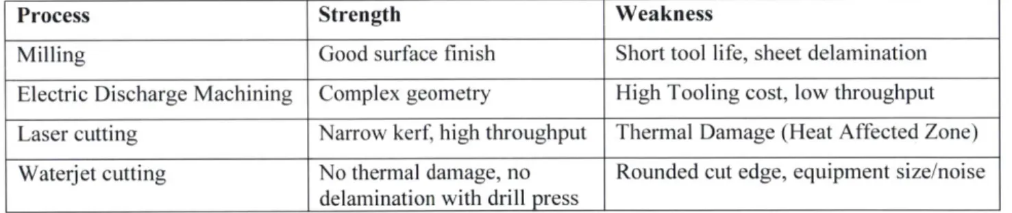
Platform Design
The wing platform (Figure 13) consists of two half wing spans (a), each attached to a central housing fuselage (b), which contains instrumentation mounting (c) and the actuation system. Beginning at the rear, a servo motor (d) is mounted to the bottom of the fuselage. A flexural delrin arm (e) is attached to the servo, which in turn is bolted to a shaft collar (f) which grips a carbon fiber tube (g). This tube exits the fuselage and passes through the wing's spar area. It terminates into a carbon fiber cap plate (h), which is bolted to another shaft collar gripping the tube. This allows rotation from the servo to twist the wing tip. The fuselage is capped with a 3D printed nosecone (i), and the lattice wings are skinned with panelized Kapton strips (j), attached to the structure via steel retaining pins (k). A central carbon rod minimizes
Panelized .005" Thk. Kapton Skin ()
-7 Steel Retaining Pins attach to Ribs (k) .125'Thk. Alum. Fuselage (b)
3/r Dia. Carbon Fiber Rod (1)
- - 1/2'Thk Alumr. Load Cell Mount (c)
ABS Nosecone (i)
1/2'Dia. Shaft Collar (f)
Dynamixel AX-12A Servo Actuator (d) 1/4'Thk. HDPE Flexure Arm (e)
1/1 6"Thk. Waterjet Cut Carbon Fiber Lattice (a) Carbon Fiber Cap Plate (h)
1/2'Dia. Carbon Fiber Tube (g)
Figure 13: Digital MAiterial Anorphing Wing P/at fbrn and Components
Platform Components
The final platform consists of the following (Figure 14):
Ribs: two rib types follow the NACA profile, but vary internally in the bending-dominated areas. Spars: uniformly spaced and split across the horizontal plane for assembly from top and bottom. Stringer: the stringer consists of two types- cells and diaphragms, which correspond to bending
dominated areas and stretch dominated areas, respectively. Stringer cells have uniform width and varying height, based on their location in the profile.
3
-- I,-'
12,Wzzzzzzz
k
~fl
AFigure 14: (L) Part type dimens ions, (R) Part groups. clockwise froin top L: all parts, ribs, stingers. spar cells spar diaphragm
Skin: The skin is made from 0.005" thick Kapton (Polyimide Film), which is cut into strips with
hole patterns on a C02 laser cutter. The skin's main purpose is to transfer the aero loads to the frame. This requires continuity and resistance to deformation. However, due to the morphing strategy, the skin must also change shape along with the wing, while avoiding wrinkling, separation from the frame, or other changes that may negatively affect the wing performance. The solution is to discretize the surface into strips, parallel with the ribs, set halfway out of phase, so that the center of each strip lands on a rib
(Figure 15). In order to maintain a continuous surface height, the strips follow an alternating up/down
pattern, with one set of strips below the other. The strips are attached to the ribs with 1/8" dia. Steel retaining pins. These pins have two legs which pass through hole patterns in the strips to grip around specific locations on the rib below. Additionally, because the tail of the rib converges into a point, a retaining feature was designed into the rib. This has a detent which mates to holes in the strip, and the small free end of the strip is then caught under a hook feature.
Figure 15: (L to R) Rib tail feature it ith hook and detent: Single strip of skin on a rib: Skin with reflective steel pins visible.
Fuselage: The fuselage anchors the wings with internal mounting structure and houses hardware
and instrumentation interfaces. The external housing is 0.125" thk. 6061 Aluminum plate, lasercut with
C02. laser and assembled via mechanical fasteners. The internal structure and instrumentation interface
Nosecone: The nosecone was 3D printed on a Stratasys Dimension 1200es FDM (Fused
Deposition Modeling) Printer. It has a uniform thickness of 3mm, an internal rib structure, and integrated mechanical attachment points to fuselage (Figure 16).
Figure 16: (L to R) Fuselage internal structure: Fuselage external structure: 3D Printed ABS Nose Cone
Boundary Conditions: the two boundary conditions are at the base and the tip of the wing (Figure
17). At the base, the wing has to rigidly attach to the fuselage to transfer forces for sensing by the instrumentation. This is accomplished by mating features on the fuselage, into which the ribs terminate. This, in addition to a zip tie at every interface, provides sufficient connection to transfer all 6 degrees of freedom. The second boundary condition at the wing tip is similar but also requires rigid connection between the torque tube and the lattice structure. This is accomplished through a series of rigidly connected parts. The torque tube is connected to the end plate by two bolts which pass through the end plate into two tapped holes in a shaft collar that is attached to the tube. The end plate is then connected to the lattice structure by a similar condition to the base- mating holes and zip ties. This allows direct transfer of torque from the tube to the lattice, resulting in the tip twisting and wing morphing.
Figure 17: (L) Fuselage-lattice mating holes with zip tie holes,- (R) end cap, shaft collar, torque tube, and zip ties at wing tip.
Manufacturing
Parts were cut on the OMAX 55100 Precision Jet Machining Center equipped with Z-Axis Pneumatic Drill Head, using OMAX Layout and OMAX Make software for CAD/CAM preparation.
The machine has the following capabilities: 60 in/min [4,572 mm/min]; 0.03" Kerf, +0.003" tolerance with 0.002"repeatability; 5,000 RPM air motor, 1/16" drill bit.
In order to ensure proper fit of the integral snap design, numerous tests were performed to determine the variation of the kerf. Significant variation arose between the cutting of several sheets (several hours of cutting), and that in order to assure kerf variation was within the tolerance of the snap fit connection, new waterjet nozzles would be used for every cut. They are considered consumables (cost-wise) in the
process, and the quality assurance validated any increase in manufacturing time. As shown below, some of the smallest features (0.003 5") are just within the tolerance of the machine (Figure 18).
US oUIO 0. 0.95'
AWJ Kerf D= OjD3 +/ O05'
.0035
AWM cut Path .
Figure 18: (L) Waterjet cut geometrv parameters: (R) Actual cut part withi waterjet kerf
The material used was a custom-made quasi isotropic layup with the following properties:
Parameter Value
Layup Orientation 0, 45, 90, 135, 180, 225, 270,
315, 3600
Sheet thickness 0.600" +/- 0.005"
Density (p) 1500 kg/m3
Young's Modulus (E) 114 Gpa
Table 2: Mechanical properties of qiasi isotropic carbon f/her composite material: Source: www. acpsales.com
Post-processing of the parts consisted of removal from the sheet (minor tabs were left to prevent part loss). This was done with a steel chisel and hammer, and required minor filing to be ready to assembly.
Assembly
The primary assembly mechanism is an integral snap fit connection. The secondary assembly mechanism is tensioned plastic cable tie (Figure 19). The assembly sequence was: 1) Place Rib on stringer diaphragm (snap fit and zip tie), 2) Fill in rib with appropriate stringer cells (snap fit and zip tie), 3)Repeat until all ribs in place, 4) Place top and bottom spar (zip tie), 5) Attach to fuselage (zip tie), 6) Skin
Figure 19: (L to R,) Pliers engage snapfit connections: Detail view o/Snapfit: Connection types (Blue= snap. Red zip-tie)
The following summarized the total build time for the wing prototype:
Process Time
Lattice Assembly 2hrs/side
Skin 1 hr/side
Fuselage Assembly + Wing Mounting 1 hr Actuator Mounting + Tunnel Prep 1 hr
Total 8 man hours
Actuation
Actuation is achieved via a flexural arm, driven by a servo motor (Figure 21). A favorable torque ratio is achieved through the geometry of the arm in relation to the actuation source and the end effector (torque tube), as shown in the diagram below (Figure 20).
T-
=
L1*
F; F = T2 2 * F; T2 T1* L 1 L2 = 2.50 in; L1 = 0.50 inIT2
= 5 * T1 F -F -+Figure 20: Alechanical advantage of wing twist arm geomeryl
Figure 21: MinAMax wing tivist (- 100)
With a max torque of 29 kg/cm @ 6.OV, this would result in around 150 kg/cm possible torque applied to
the wing tip. Comparatively, driving the wing twist directly with zero mechanical advantage would require a servo that weighs 8 times as much and is 3 times as large. Controls were achieved through a Mini Maestro 12, a small yet efficient microcontroller with a native USB interface and internal scripting control. Due to its small size, it is mounted to the underside of the fuselage, in between the flexural arms.
Flight Performance
The digital material morphing wing has successfully undergone wind tunnel testing in the Langley Research Center 12-foot low speed wind tunnel (Figure 22). The ground-based aerodynamic testing was aimed at assessing the benefits of the aeroelastic morphing concept in an experimental approach. Goals included demonstrating operational feasibility, exploring structural stability while delivering aero performance, and augmenting computational predictions. Further goals included assessing basic airframe open-loop stability, controllability of shape under loads, control power (aerodynamic), database
generation for simulation and analytical studies, and demonstration of drag reduction potential. These tests would allow study of the fluid-structure interaction of the morphing wing to explore the concept and
mature the feasibility, define how the shape changes affect the aerodynamics, and determine the control authority requirements to counter structural compliance.
Figure 22: Overviewi ofvariables for norphing wing wind tunnel testing
A solid wing version was created with the same geometry and discrete control flaps typical of commercial
airplane wings to produce baseline data for comparison to morphing performance (Figure 23).
The testing setup fixed the wing and instrumentation fuselage to an armature with an internal
6-component strain gage balance (Figure 24). The parameters were dynamic pressure qbar (wind speed;
14-52 mph), angle of attack a (-8 to 90'), sideslip angle , (+/- 90'), and wing twist angle 0 (+/- 100).
Figure 24: (L) 6-component strain gage mounting touselage: (R) Wing setup in wind tunnel
The morphing wing easily withstood aero loading across a typical UAV flight envelope, including: dynamic pressures up to 7 psf (10 Pa), speeds up to 77 fps (23 m/s), through post-stall angles of attack
(>16*), and moderate sideslip angles (generally only +/- 4 , limited to 16').
The morphing wing at neutral twist showed similar aero properties as the rigid variant in performance and static stability and roll-damping. It allows for improved control options to enhance efficiency as
compared to conventional design. Controls-active tests demonstrated viability of morphing structure active twist response dynamics against realistic loads and states. The morphing wing has the ability to modulate forces while maintaining trim more so than the rigid wing. The morphing wing provides increased lift with reduced drag compared to the conventional flap in the pre-stall regime.
Two unexpected phenomena discovered through testing were flutter suppression and high frequency morphing (Figure 25). At a high AoA and qbar, there was significant flutter on both wing tip trailing edges. In an attempt to suppress this, the wing tip was twisted gradually, until the airfoil shape became optimal for the conditions and was able to reattach the viscous flow. This indicates that wing twist can be used to dynamically attached flow in sub-optimal conditions, which translates to optimization of flight performance in varying conditions. In the next experiment, the sting mount was set to "free roll", and at a constant AoA and qbar, a high frequency closed-loop cycle of +/- max wing twist was performed. The result was a high frequency morph that caused a controlled roll about the roll axis. This indicates that
Figure 23: (L) Flutter suppression testing: (R) High r-equency roll testing For more extensive numerical and experimental results, please refer to (43).
2.2.3 Summary and Further Research
In summary, this chapter has introduced a novel approach for the design, analysis, and manufacturing of composite aerostructures through the use of digital materials. This has been shown to reduce time and complexity compared to traditional composite structures. A digital material morphing wing was
presented, and it was shown to perform as well as a rigid wing, with additional performance capabilities that can improve flight efficiency and control. The main contribution of the chapter is the description of digital materials and discrete lattice structures, the manufacturing methods to produce these parts, and the performance capabilities of structures built with digital materials.
The work presented here will proceed for several years at NASA in the form of entire digital material aircraft that can morph in flight. Additionally, pressure sensing skin is currently being designed to give continuous feedback and allow for dynamic responsive morphing based on external conditions and desired flight applications.
3. Digital Material Space Structures
3.1 Background
Space structures- such as large surfaces to provide power, large antennas and mirrors for astrophysics missions, and space platforms to provide area for general utilization- have three main concerns for use on orbit: application-based structural performance, launch vehicle packaging, and on-orbit deployment. This chapter addresses these concerns in the application of digital materials to space structures.
Space applications
Aside from specialized mission specific components, generally space structures can be divided based on their mass-normalized structural requirements (44). For example, a precision reflector strut needs high accuracy, a space station strut needs high stiffness, and an aerobrake strut needs high strength.
Figure 24: (L to R,' Platform. Beam, Aperture Space Structure
Trusses can be used to build a wide variety of structural shapes as shown below. Platforms and beams can be used as a skeletal framework to which other components or modules can be attached, forming a large
integrated spacecraft. Trusses can be built very accurately and covered with mirrored panels to form large very precise antennas or reflective surfaces (Figure 26).
There are many examples of these structures, either proposed, or currently in space:
Plaforms: habitats, pressure vessels, enclosures, hangars, and keels (45) (46) (47)
Beams: masts, booms, and baselines (48) (49) (50).
Apertures: precision segmented reflectors (51) (52) , star shades (53), solar power generation (54)
(55), and antennas (50) all fall within this category. Transportation Considerations
The space shuttle program was originally designed to bring 24,000 kg of cargo to Lower Earth Orbit per week. This (partially) re-usable spacecraft encouraged NASA researchers to propose large space
structures, which would be enabled by this ability to cheaply transport large payloads into space.
Numerous proposals involved sending large amounts of raw materials into space for in-space fabrication and in-space assembly (explained below). The space shuttle's operational costs were much greater than expected. In 1972, then-NASA administrator James Fletcher told Congress that the shuttle would operate at a cost of $10.5 million per flight, but it ended up costing 20 times this (56). Due to these high costs,
NASA could not develop other systems, and was forced to use it to complete the International Space
Station (ISS). Since 1981 there have only been 135 shuttle launches.
The default solution, then, was to fabricate on earth, launch into space, and assemble large pre-built structures on orbit. This is how the ISS was built. There are two main consequences to this strategy:
1. Structures are mass and/or volume limited by current launch shroud capabilities. For example,
current largest launch shroud is Ariane 5, with payload to LEO of 35,000lb and to GTO of 15,0001b and volume of 7.7m x 4.5m x 4.5m) (57). The average payload density delivered to low Earth orbit (LEO) by most medium to heavy launch vehicles is about 65kg/m3. Hypothetical structures should maintain this
launch density; otherwise they will either be sub-optimal due to volume or mass (Figure 27).
2. Structures undergo massive vibration and shock loads while launching into orbit, with
acceleration upwards of 9 g's. This means structures must be designed to withstand these loads, which are much larger than the loads structures experience in the microgravity of space (58).
Due to these challenges, it is valuable to reconsider alternate methods for assembly space structures. These are presented in the following section.
0I 2I 1000 100 10 0.1 0.1 1 10 100
Deployed Areal Density, Kg/n2
1000
Figure 25: Comparison oftmass and packaged volunes ofdeployables with respect to optimal launch shroud density
Construction approaches
There are three main approaches to the implementation of space structures: deployables, in-space assembly, and in-space fabrication.
Deployables
Typical deployable structures are solar panels, antennas, radars and masts of satellites (objects much larger than the launch shroud), but most other structures sent into space deploy in some way, including thermal radiators, satellite hardware (supports, joints, mounts), crew quarters, and transportation tunnels, due to the need to be volumetrically efficient. This work will address the first category of deployables.
Deployable space structures operate by tightly packing into a launch shroud, launching, and then
expanding or unfurling into its final, larger configuration once in orbit. This is an approach that has been used since the advent of space technology. The unfurling mechanisms include articulating booms, umbrella-like antennas, unfolding star shades, and coilable masts (Figure 28). Scale is limited by launch
shroud capacity, but scale also corresponds to performance. To achieve higher packing efficiency,
complex deployment schemes arise, which add more mass and volume for unfurling actuation, and lead to
35 Launch 20 Density 7 ' 65 (Kg/rn3) 7 7 7,200 .. ~. ,7 7 \,. 7 7 77 7 777~77 7 7 7 7 7 7 7 7 7 7 7 7 7 / 7. / 7 7 / 7
increased risk of error and mechanism failure (59). Space systems experience their highest failure rate during deployment, but typically behave properly once deployed (60).
Deploying
~
45Sm 62M
Figure 26: DeploVahles (L to R): Un/urlng Membrane (53), Coilable Solar Sail Mast (61). and Folding Segmented Mirrors (62)
Deployable truss structures have often been used to address the unique structural requirements of the space environment (63) (64). The combination of severe launch loading, volume and total mass constraints, and low (as-deployed in-service) loading requirements necessitates the use of structural systems that display packing efficiencies on the order of 100:1, (65) (66) .Proposed solutions to this set of constraints focus on the design of a monolithic device that can be packed in a pre-assembled
configuration and, either by the controlled release of internally stored energy or via external mechanisms expands into the operational configuration. Mikulas (67) characterized the theoretical performance of three types of deployable trusses: tubular, longeron-based trusses, and isogrid walls. Experimentally, many have explored these different truss types with a diverse array of deployment mechanisms, including coilables (61), inflatable rigidizables (both longeron (68) and isogrid (64)), extremely high expansion foldables (65), and skewed-compression systems (49) (48) (69). For historical overviews of deployable space structures, refer to (70) (71) (72).
Deployables are almost always volume-limited. To illustrate this, the Hubble Space Telescope (HST) occupied 4% of the launch mass and 2% of the volume capacity of its launch vehicle. The JWST will occupy 15% of the launch mass and 50% of the volume capacity of its launch vehicle. Being (more) mass limited is a desirable property that is difficult to attain with traditional deployable structures (73)
Decades of refinement have reduced error rates, but anomalies are not uncommon, and are just as costly. High profile instances include the Galileo High-Gain Antenna, whose umbrella-like antenna failed to unfurl (74); the Mars Express Spacecraft, whose partially unfurled jointed boom required corrective
spacecraft maneuvers (75), and the Inflatable Antenna Experiment, whose unfurling caused unexpected dynamics, overwhelming the attitude control systems (76). The planned JSWT must deploy a 25 m2 aperture and a tennis court-sized sunshield, and must fit within a 4.5m diameter launch shroud (62).
The JWST has a 6.5m diameter reflecting dish. The challenge of deploying a 25m diameter dish is nearly insurmountable due to deployable mechanism packing inefficiency. It simply could not fit within a launch shroud (73). A strategy for building structures bigger than the largest deployable that can fit within a launch shroud is to launch parts or material into space and build the structure on orbit.
In space assembly
In Space Assembly (ISA) proposes the construction of space structures by sending a kit of parts into orbit, and then assembling these parts with either Extra Vehicular Activity (EVA) -human based assembly, Extra Vehicular Robotics (EVR) -robotic based assembly, or a combination of both (Figure 29).
Figure 27: In Space Assenbly (L to R): ACCESS (77), Tele-Robotic Trius Assembly (78). Autonomous Robot Inspection (79)
Since the advent of the space shuttle program, NASA engineers have been speculating on the in-space assembly of large space structures. They sought to build space stations (47) and space construction
facilities (44) from modular construction kits. However, the realities of both EVA and EVR, combined with the inefficiency of the space shuttle, forced them to scale back their designs. Regardless, testing continued in the form of Experimental Assembly of Structures in EVA (EASE) and Assembly Concept for Construction of Erectable Space Structures (ACCESS). EASE relied EVA to guide semi-automated assembly of struts into large truss booms. ACCESS required robotic armatures to move and locate "human end effectors" to assemble smaller truss structures (77). Mobile versions would allow a platform to move along the completed structure, with robotic arms and astronauts, to assemble new structure (80).
EVA-only assembly has been quantified (81), and for small scale applications can be faster than EVR
(82). EVA has to avoid fatigue and danger to astronauts. EVR has to carefully path plan motions, to avoid
collisions. Assembly rates for both processes are limited by ease of operation of hardware. (73)
EVR has been explored extensively due to the promise of significant improvements in automation, throughput, and parallelization. The construction techniques, and complexities involved, become crucial. Significant work has been done on struts and nodes with locking joint hardware, which allow robotic
assembly of large truss structures (78). Other approaches replace locking joints with jigging and welding
(28). Telerobotic (human controlled) robotic arms are used on the ISS (83). More autonomous robotic
assembly systems propose robots that build, inspect, and repair large truss structures remotely (79).
In space fabrication
In Space Fabrication (ISF) differs from In Space Assembly in the following way: rather than a kit of parts being sent into space, comparatively more "raw" materials are sent up. The material form can vary, from rolls of thermoplastic tape to pellets of fiber reinforced plastic- but the main argument is that the packing efficiency of these materials is better than more finished products and that the in-situ fabrication process
allows for greater control and flexibility than assembly of predetermined parts (Figure 30). The aim is to overcome volume limitations of launch, and be able to optimize payload for launch shroud density.
Figure 28: In Space Fabrication (L to R): SCA FEDS [55]. Geodetic Beam Builder [56j. Spidertab [57]
Several "Beam builder" machines were designed to extrude composite longerons and assemble them with cross members by ultrasonic welding to form large truss structures (84), and others would extrude
geodetic beams (85). These machines weighed thousands of kilograms, consumed large amounts of energy, and nearly filled the space shuttle launch shroud.
Current approaches propose beam extrusion combined with additive manufacturing end-effectors mounted on globally positioned robots with multi DOF arms (86) (87). Thermally intensive processes (e.g., pultrusion, thermoplastic melting), require significant shielding from temperature differentials between cosmic background temperatures (~-455 F). Due to the continuous nature of robotic construction, metrology and error correction require additional sensing and tracking systems.
In space fabrication approaches are likely to be more mass limited than volume limited.
Incremental Robotic Assembly
An important body of work this research draws from is that of incremental robotic assembly of structures. The goal of robotic assembly of large structures from modular components has seen a variety of proposed solutions (Figure 31). These include robots arms with many degrees of freedom relative to the built
structure (79) (88), assembly with UAVs (89), robots which crawl along the built structure to place elements (90), (91), and construction platforms (92).
Figure 29: Incremental Robot Assemhly (L to R): Base Plane (92), Traversing (91) Brick LaYing (93)
The use of unattached robot arms involves multiple degree-of-freedom (DOF) manipulators to place elements in their correct positions. When this method is applied to in-space assembly, these robots are usually called "satellite arms" (94). With this method, the separation of the assembler from the structure requires a global external positioning system in order to align the elements, adding to the complexity and limiting the scale of the final design to that of the positioning system (86).
Prior work that uses the built structure as a reference to place the next set of elements include robots that traverse bi-directionally geared truss members connected at nodes (91) and bricklaying robots that manipulate and place volumetric elements with integral latching interfaces (93). The work of Galloway
(92) uses an established base plane to assemble each layer of the system, with a final elevator mechanism
that clears the building area and enables another layer to be constructed below the previous. By connecting these floors in a two-dimensional array, large volumes can be constructed layer by layer.
Most of the strategies proposed focus on designs that employ mechanical struts locking into node parts. These studies have made good progress, especially given the apparently intrinsic need for complex interlocking structures and robots that can manipulate these elements. Galloway (92), Staritz (79) , and Senda (88), show multiple-DOF arms integrated into a moving super structure to enable the range and precision required to place all of the elements.
The systems proposed by Galloway (92) and Nigl (91) include procedures to perform modifications to the final structure. In the former case, a flexure-based clamp attaches struts to nodes, and in the latter
3.2 Space Robot Universal Truss System (SpRoUTS)
The work presented in this section was completed in collaboration with Kenneth Cheung and Daniel Celluci (NASA Ames Research Center); and sponsored by NASA Space Technology Research Fellowship.
In response to the challenges presented by the realization of space structures, the application of digital materials to in-space assembly was investigated. The objectives were the following:
-reversibly assembled structure
-flat pack parts for transportation efficiency
-minimum degree of freedom (DOF) relative robotic assembler
In order to satisfy these constraints, a part was designed with integral snap fits that can be stored flat and then folded into a larger, stable volume by a simple folding robot. Initial results are shown (Figure 32).
01: Flat Pack Geometry and Morphology n number of sides
Flat Pack Panea
Fold into Bottom of Previousiy Aswmbed Panel
Snap FitAssemsblya n= 4 I'N\ , -4L -osr Fotrn 'wt -Jn6
LI
(Conservative) Ftatpack Aspect Aatto
Figure 30: (L) Overview of folding part geometries and integral snap fit connections: (R) Comparison ofpart size to assembler
size, and part storage size to assembled truss size.
64L
AsseedeetctunputI
r
4L