First International Conference on Bio-based Building Materials June 22nd - 24th 2015 Clermont-Ferrand, France
SUSTAINABLE BUILDING WITH LOCAL MATERIAL: A CASE STUDY
V.-H. Tran 1, 2 , J.-C. Morel 1, *, Q.-B. Bui 3, S. Hans 1 , M. Oggero 21
ENTPE, 3 rue Maurice Audin, 69120 Vaulx en Velin, France.
2 Filiaterre, 3 Place A.Medecin, 06100 Nice, France.
3 Université de Savoie, LOCIE – CNRS UMR5271, 73376 Le Bourget du Lac, France.
*
Corresponding author: [email protected]
Abstract
Nowadays, using local materials in construction such as in-situ soils is attractive because on one hand, these materials have low embodied energy and on the other hand, houses constructed with soil material present an interesting living comfort thanks to their interesting hygro-thermal behavior. This is why several researches have been recently carried out to study soil materials. However, one difficulty of the constructions using local materials is that they must satisfy several exigencies of the modern regulations which are established for conventional materials (e.g. concrete): mechanical, thermal performances, durability and earthquake resistance. This paper presents a project (three buildings) using local materials (in-situ soil and wood) in Nice city (France). Firstly, specifications of the project are presented: architecture, material characteristics (by laboratory tests). Secondly, a LCA study is presented which compares a villa of this site and another virtual villa constructed by a conventional method. The results illustrate the sustainability of this project. Finally, the earthquake performance is studied which consists of two approaches: a numerical modelling and the in-situ dynamic measurements which enable to validate the numerical model. The results show that these constructions can satisfy seismic demands following Eurocode 8.
Keywords:soil material, sustainable development, mechanical characteristics.
1 INTRODUCTION
Local materials are directly available on site. They are used by humanity from centuries as earth (rammed earth, adobe, cob,…), stone (dry stone masonry and rubble stone masonry), and wood. The construction techniques using local materials are still widely used today in developing countries, thanks to their lower construction costs in comparing to conventional constructions (such as reinforced concrete or metal structures). The reason is that conventional materials are not always available in these countries and must be imported, that significantly increases the cost. In addition, the labor cost is not expensive, so the use of local materials has a positive social aspect by providing work to local workers
However, in developed countries, most of these materials were dropped consistently over the past six decades for two main reasons. First, the labor cost in these countries is very important, which is not favorable for the constructions requiring important labor. Then, the current design regulations are established mainly for industrial conventional materials. There are few standards for
non-industrial materials due to the lack of scientific knowledge on them.
Nevertheless, the past few years have witnessed a renaissance of local materials in developed countries, mainly due to the urgent demands of sustainable development. Non-industrial local materials gradually found their place on construction sites because they are taken and manufactured directly on site, which provides low embodied energy [Morel 2001].This provides not only a reduction of energy consumption, but also a reduction of CO2 emissions that is the main cause of
the global warming. In addition, most of non-industrial local materials are re-usable (stones and earth) or renewable (wood) which is sustainable in reduction of environmental impacts.
2 THE CASE STUDY
2.1 Puddingstones and their presence in Alpes-Maritimes (France)
The puddingstones are widely present in the Alpes-Maritimes region (Southern France), so there is a promising perspective for a sector of "puddingstone constructions" in this region. The size distribution of the puddingstone soil is presented in Tab. 1.
Tab.1: size distribution of puddingstone
< 0.002 mm 0.002 -0.063 mm 0.063 - 2 mm > 2 mm
0.5% 2.5% 30% 67%
2.2 Project “Domaine des Galets”
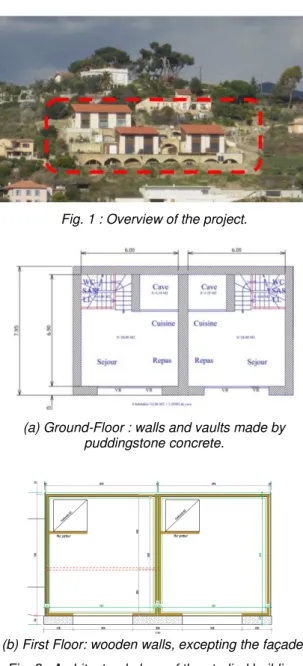
The object of this study is a construction program (“Domaine des Galets”) realized by the Filiaterre company and using the puddingstone soil. Fig. 1
shows an overview of the project. The main elements include three buildings numbered buildings A, B, C whose the first two are identical. They were built in 2013 in Nice City by using the puddingstone concrete. In addition, many secondary elements were also built by using this material, such as: the arches supporting the terraces, garages and retention basin. All these elements are vaulted shape. This paper focus on the building B which represents the project. The architectural plans of the building are given in the Fig. 2. It includes a
Ground-Floor (GF) and the first floor containing a mezzanine. While all the elements of the GF are made of puddingstone concrete, the elements of the first floor are made of wood, with the exception of three facades (Fig. 2b).
Fig. 1 : Overview of the project.
(a) Ground-Floor : walls and vaults made by puddingstone concrete.
(b) First Floor: wooden walls, excepting the façade. Fig. 2 : Architectural plans of the studied building.
A cross section of the vaults of the studied building is shown in Fig. 3. There are two arches of 6 m
opening. These arches are supported by three walls: two external (left, right) and one interior. The two external walls are two batters with a thickness varying from 0.5 m at the top to 0.65 m at the down. The inner wall has a constant thickness of 0.6 m. The opening of the arches is also the transverse space of the building.
Fig. 3 : Detail of the arch made by puddingstone concrete
3 MATERIAL CHARACTERISTICS
3.1 Formulation of the puddingstone concrete The presence of clay in the puddingstone soil is low (<0.5%, Tab. 1), a binder should be added to produce the building material. The added binders can be cement, lime or clay. The manufacturing is similar to that of conventional concrete to reduce the production time. An optimization study was performed in [Tran 2014] to investigate different possible compositions for the puddingstone concrete: type and rate of added binders; amount of water; modification of the grain size distribution. Mechanical tests were carried out in laboratory for each composition; the results were compared to exigencies of the current regulations. Finally, the chosen composition for the project “Domaine des Galets” was a cement amount of 10% (by weight) and water/cement ratio of 1, which gave the maximum compressive strength. The used cement was CEM II 32,5R.
3.2 Compressive strength
Tests on the standard specimens
In a first step, standard cylindrical specimens (16cm-diameter x 32cm-height) were manufactured to investigate the mechanical properties of the material. To ensure the hypothesis of a homogeneous specimen, gravels bigger than 50 mm have been eliminated by using a 50mm-sieve. Before compression tests, the specimens were surfaced on the upper side by cutting with a specific saw. Then, uniaxial compression tests were carried out to determine the Young's modulus and the compressive strength of the material.
To determine the Young's modulus, a loading-unloading cycle was performed. Three extensometers were used to measure strains in the central part of the specimen (Fig. 4), [Bui 2014].
Then, the specimen was loaded until the failure to determine the compressive strength. The mean values of compressive strength and Young's
modulus were 8.2 ± 0.15 MPa and 13600 ± 300 MPa respectively.
Fig. 4: Compression test on a (16D x 32H) specimen
Tests on representative volume element (RVE)
Due to the presence of an important amount of big gravels in the puddingstone soil (up to 80 mm), more important size of the specimen is necessary. This could show influences of the specimen size on the mechanical characteristics.
Manufacturing of VRE specimens:
Two VRE specimens were manufactured: first, a cylindrical column of 30 diameter and 110 cm-height was made. Then, this column was cut in two specimens with a chainsaw (Fig. 5). So these
specimens had a slenderness ratio of 1.83. The specimen height was limited to 55 cm due to the maximum height of the press.
Fig. 5 : Cutting the puddingstone concrete column Compression tests
Uniaxial compression tests were carried out on VRE specimens by using Schenck press with a force sensor of 2500 kN (Fig.). Three LVDTs were used
to measure strains in the central part of the specimen. The bottom steel plate is movable to facilitate the installation of the specimens the specimens were heavy and could not bring in hand. The compression tests were controlled in displacement with a speed of 0.01 mm/s.
Results obtained :
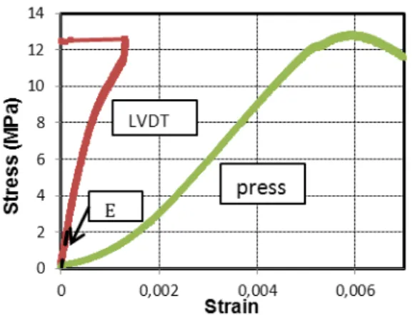
Fig. 7 shows results obtained by the uniaxial
compression test on a VRE specimen. It includes two stress-strain curves, obtained with the strains measured by the LVDT and by the displacement sensor of the press. The Young's modulus was measured on the first portion (up to the stress of 2 MPa).
Fig.6: Compression test on a (30D x 55H) specimen
Fig. 7 : Stress-strain curves of a VRE specimen in puddingstone concrete.
The mean values of the compressive strength and the Young's modulus of the VRE specimens were of 12 ± 0.57 MPa and 15600 ± 400 MPa, respectively. This shows that in the case of puddingstone concrete, VRE specimens have a compressive strength 1.5 times greater than that of the 16 cm - diameter specimens. Indeed, big gravels play a favorable role, significantly increases the compressive strength of the material. Consequently, mechanical characteristics determined from “small” specimens should be corrected by a coefficient. The puddingstone concrete at 10% of cement by weight corresponds to 170 kg cement by m3. For
ordinary concretes, the cement content is 300 - 400 kg/m3. This explains why the puddingstone
concrete’s compressive strength is lower than that of ordinary concretes. However, for residential low rise buildings (1-3 stories), the puddingstone concrete’s strength is acceptable.
3.3 Tensile strength
The splitting tests were performed on cylindrical specimens of puddingstone concrete to determine the tensile strength (Fig. 8). The mean tensile
strength obtained by splitting tests was of 1.2 ± 0.1MPa.
Fig. 8: Splitting test on cylindrical specimen.
In this case the puddingstone concrete, the study of [Tran, 2014] showed that from the compressive strength of the material, its tensile strength can be estimated according to the expression (1):
ft = 0,6 + 0,06fc (1) where: ft and fc are respectively the tensile and compressive strengths of the material.
No testing has been performed on VRE specimen to determine its tensile strength. Therefore, following equation (1), the tensile strength of the VER can be estimated of 1.32MPa.
4 LIFE CYCLE ANALYSIS (LCA) 4.1 Occupation phase
Dynamic thermal simulations were performed for the studied building. Their details will not be presented here. Thanks to the bioclimatic architecture (thick walls in puddingstone at 1st story to have a good thermal inertia; wooden structure at 2nd story to
have a good isolating; wide glazing door in southern façade to have an important solar input), the primary energy consummation of the building during the occupation phase is of 40 kWh/m2/an, which corresponds to a low consumption category. 4.2 Embodied energy
In the past, the embodied energy (energy necessary for the transformation, transport; from the extraction of primary material to the finished product) of the buildings was usually neglected, because it was low by comparing to the energy consumption during the occupation phase. However, with the rising in thermal performance of the modern buildings (low energy consumption or positive energy), the embodied part becomes considerable in the life cycle of a building.
A LCA investigation was carried out in [Bouldoires 2014]. Two buildings were studied: the first was the building B of the present project and the second is a “virtual” building which had the same architectural plans, but constructed by conventional materials which are currently used in France for individual houses: cement bricks for the walls, reinforced
concrete for floor. The thickness of the walls in cement bricks was the current thickness for this type of construction (25cm), however, the thickness of insulation layers of the “conventional” building was calculated in order that the same walls in the two buildings give the same thermal resistance. This leads that two buildings have the same energy consumption for the occupation phase.
The life cycle was assumed to be 50 years.
The results showed that, although the actual building (building B) consumed a more important quantity of materials (40%), due to the important thickness of the walls, it had energy consumption less than 60% of the virtual conventional building. The CO2 emission of the actual building was also
less than 60% of the actual conventional building. The study showed also the embodied energy of the actual building was at 10% of the total energy consumed during the building’s life cycle. This means the embodied energy is not negligible for the recent constructions.
5 ASSESSING THE SEISMIC
PERFORMANCE
In this section, the seismic performance of the building is evaluated. First, the dynamic characteristics of the building were identified by the noise in situ measurements. This enables to understand the dynamic behavior of this type of construction and then to validate a numerical model. Secondly a numerical model of the building, using the finite element method was developed and validated by comparing with experimental results. Based on the numerical model, a simulation of the seismic action was carried out according to the European standard EC8. This helps to study the response of the building in case of earthquake and then to evaluate the seismic performance of this type of construction.
5.1 Modeling the building using the finite element method (FEM)
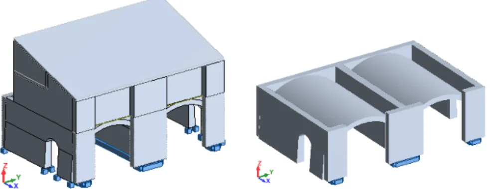
In this section, the modeling of the building using the finite element method is presented. In order to study the behavior of the structure under seismic loading and then to estimate its vulnerability, the FEM software "Robot Structural Analysis" was used. The geometry of the building of the model is shown in the Fig. 9. The walls are considered to be
embedded in the soil at the foundation surface. Two materials defined in this model are the puddingstone concrete and wood. The elements in puddingstone concrete include the vaults and walls of the 1st story and the facades of the 2nd story (Fig. 9). Other elements of the 2nd story are in wood. The
characteristics used for these two materials are summarized in the Tab. 2.
Fig. 9: Modeling the building B. Left: the entire structure; Right: walls and vaults in puddingstone concrete of the 1st story
Tab. 2 : Characteristics of the materials used
Characteristics Puddingstone concrete Wood Specific weight (kN/m3) 22 5,5
Young's modulus (MPa) 15600 9000 Poisson's ratio 0,2 0,03 Following the modal analysis obtained by the model, the first natural frequencies of the structure are: f1 =
28.08 Hz and f2 = 36.13 Hz.
At the first natural frequency (f1 = 28.08 Hz), the
modal mass in the y-direction (My = 76.1%) is
dominant compared to modal masses in other directions (Mx = 0% and Mz = 0%). So the first
natural frequency corresponds to the first vibrating mode in the y-direction. Also, the second natural frequency corresponds to the first vibrating mode in the x-direction (Mx = 76.46%; My = 0% and Mz =
0.2%).
5.2 Validating the numerical model by in-situ vibrational measurements
When the building was in the end of the construction, in-situ vibrational measurements were carried out. The triaxial accelerometers were used (Fig. 10) to measure the acceleration of the building under the “ambient noise” (caused by the micro-earthquakes, ocean waves, …). More details about in-situ vibrational measurements can be seen in [Bui 2011] or [Hans 2005] for example.
Fig. 10 : Vibrational measurements by triaxial accelerometers.
From the results obtained in the time domain, after a signal processing, the results in the frequency domain were obtained. The difference between the two first natural frequencies identified by experiments and that of the numerical model was
less than 5%, which showed that the numerical model was acceptable.
5.3 Assessing the earthquake performance
Simulation of seismic loading:
Based on the model adopted for the building, a simulation of the seismic loading was carried out to study the behavior and vulnerability of the structure in the case of earthquakes. The seismic loading was simulated according to demands of Eurocode 8. The following parameters were used to define the earthquake solicitations:
- The ground of the construction project is in class A according to the classification of the EC8.
- According to the France’s seismicity map, Nice city, where the project is located, is a medium seismicity zone (seismicity 4, the higheest seismicity zone of France Metropolitan). The reference ground acceleration of the class A for this seismicity zone is: agr = 1.6 m/s2.
- For residential buildings that are classified as category of importance II, the coefficient of importance is of 1 (γ1 = 1). Then, the calculating
acceleration for a soil of class A is:
2 1
.
1, 6
g gr
a
=
γ
a
=
ms
−(2) - The model was performed using the elastic response spectrum of type 2 (Eurocode 8) and the complete quadratic combination method was adopted to combine the modes of vibration.
Combination of actions:
According to Eurocode 0 (European standard EN 1990 acting on the basis of calculating the structure), to evaluate the seismic performance of the structure, the participation of seismic actions should be investigated by the combinations indicated in expressions (3) - (6).
Comb-1 = G "+" EEdx "+" 0,3EEdy "+" 0,3EEdz (3)
Comb-2 = G "+"0,3EEdx "+"EEdy "+" 0,3EEdz (4)
Comb-3 = G "+" 0,75Q"+" EEdx "+" 0,3EEdy "+"
0,3EEdz (5)
Comb-4 = G "+" 0,75Q "+" 0,3EEdx "+" EEdy "+"
0,3EEdz (6)
where : G and Q are the dead loads and operating
loads; EEdx, EEdy et EEdz are respectively the effects of the action due to the application of seismic actions conducting along the axes x, y and z; "+" means the combination of loads.
Limit criterion for the evaluation of seismic performance
Seismic performance evaluation method of the structure based on the admissible stress is to verify that the maximum stresses in the structure are less than the admissible strength of the material. The stress field of the entire structure is determined by the numerical model using the FEM, where the behavior of the puddingstone concrete is assumed to follow the isotropic linear elasticity. Therefore, it is necessary to limit the response of the puddingstone concrete elements in the elastic range. The compressive strength and tensile strength were obtained by laboratory testing. In this case of the puddingstone concrete, the elastic limit in compression and tension are assumed to be 60% of the strengths (which correspond also to the coefficient of ordinary concretes in Service Limit State). This elastic threshold is taken according to which is systematically used in the case of conventional concrete. We get:
0, 6
e cf
cσ
=
(7)0, 6
e tf
tσ
=
(8) where : e cσ
and e tσ
are the elastic limits compression and tension of the puddingstone concrete;f
c andf
t are the compressive and tensile strengths of the puddingstoneThe elastic limit criterion is assumed to be given by the following conditions:
max max e c c e t t
σ
σ
σ
σ
≤
≤
(9) where: max cσ
and max tσ
are the maximum compressive and tensile tress in the structure. Therefore, the justification of the stability of the structure consists of checking the condition given by the expression (9).Evaluation of the seismic performance
Main stress corresponding to each load combination had to be done in the whole structure. The justification of the stability of the structure is briefly presented in this section to offer a simplified procedure for the case of a puddingstone concrete building. For all cases of load combinations, the maximum compressive stress is of 0.34 MPa, and the maximum tensile stress is 0.37 MPa.
max max
0, 34
0, 37
c tMPa
MPa
σ
σ
=
=
(10)Applying the expressions (7) and (8), we also get:
7, 2
0,8
e c e tMPa
MPa
σ
σ
=
=
(11)The maximum compressive stress is less than the allowable compressive stress, corresponding to a safety factor of 21. Also, the maximum tensile stress is less than the allowable tensile stress, with a safety factor of 2. So the conditions given by (9) are justified. Therefore, the stability of the structure is ensured in case of earthquake.
6 CONCLUSIONS AND PERSPECTIVES The difficulty of constructions using local materials is that they must satisfy several exigencies of the modern regulations which are established for conventional materials. This paper showed how a recent project using local soil to make a soil concrete which can meet the modern exigencies. The earthquake performance was also tudied which consisted of a numerical modelling and in-situ experiments to validate the model. The results showed that the studied building could satisfy seismic demands following Eurocode 8.
The results for LCA showed also that thanks to using a local material, the embodied energy of the studied project was lower than that of a virtual conventional building. This led to a reduction of 60% of energy consumption and CO2 emission for a life
cycle. The embodied energy of the studied building was 10% of the total energy consumption in its life cycle, which was not negligible.
7 ACKNOWLDGEMENT
This research is funded by the project PRIMATERRE - ANR-12-VBDU-0001-01 Villes et Bâtiments Durables.
8 REFERENCES
[Bouldoires 2014] Bouldoires C., Janin C. Etude de l’impact environnemental de constructions en matériaux locaux. Project Report (in French), May
2014, Polytech Annecy-Chambéry, France.
[Bui 2011] Bui Q.B., Morel J.C., Hans S., Do A.P. First exploratory study on dynamic characteristics of rammed earth buildings, Engineering Structures, p. 3690-3695, 2011
[Bui 2014] Bui Q B, Morel J C, Hans S, Walker P. “Effect of moisture content on the mechanical characteristics of rammed earth”, Construction and Building Materials, 2014.
[Eurocode 0] Basis of structural design, EN 1990:2002 (2004).
[Eurocode 2]. Design of concrete structures – part 1-1: general rules and rules for buildings”, NF EN 1992-1-1, P 18-711-1, October 2005.
[Eurocode 8] EN 1998-1:2004. Eurocode 8: Design of structures for earthquake resistance, European Commitee for Standardization (2009).
[Hans 2005] Hans, S., Boutin, C., Ibraim, C., & Roussillon, E.. In situ experiments and seismic analysis of existing buildings Part I: Experimental investigations, Part II: Seismic integrity threshold. Engineering and Structural Dynamics. Vol 34, 1515-1546 (2005).
[Morel 2001] Morel, J. C., Mesbah, A., Oggero, M., & Walker, P.. Building houses with local materials:means to drastically reduce the environmental impact of construction. Building and Environment vol 36, 1119–1126 (2001).
Tran, V. H.. Mechanical optimizations for constructions using local materials. Lyon, France: PhD thesis (in French), ENTPE Lyon (2014).