Received: 18 November 2003 Revised: 14 April 2004 Accepted: 23 April 2004 Published online: 31 July 2004 © Springer-Verlag 2004
Abstract The characteristics of syn-chrotron X-ray sources—quite dif-ferent from those of conventional sources—are exploited by several new imaging techniques. These tech-niques expand the capabilities of conventional radiology and find in-teresting application in special cases. We briefly review the basic princi-ple, applications and limitations of the most important of them: mono-chromatic mammography, two-wavelength digital subtraction angi-ography, phase-contrast/edge-en-hancement imaging, diffraction-en-hanced imaging and microtomogra-phy.
Keywords Synchrotron · Storage ring · Undulator · Wiggler bending magnet · Phase-contrast ·
Diffraction-enhanced imaging · Tomography · Digital subtraction Reto Meuli
Yeukuang Hwu Jung Ho Je
Giorgio Margaritondo
Synchrotron radiation in radiology:
radiology techniques based
on synchrotron sources
Introduction
Part I of our review [1] explained that the properties of synchrotron X-rays are quite different from those of standard sources based on the Röntgen mechanism. We saw in particular [2, 3] that synchrotron sources provide highly collimated and powerful (bright) beams with lin-ear polarization (circular polarization for special de-vices). Specifically, undulators and wigglers provide beams collimated both in the horizontal and in the verti-cal directions because of the small source size and angu-lar spread along all directions. Bending magnet sources instead produce fan-like beams with a very small angular
spread in the vertical direction; the horizontal spread de-pends in this case on the angular range collected by the beamline.
These advanced characteristics—and in particular the emission geometry—make it difficult to compare direct-ly a synchrotron source with standard radiology sources, conventionally characterized by the X-ray tube voltage and by the tube current. As a rough comparison, a bend-ing magnet synchrotron source is at least 5–6 orders of magnitude brighter than a conventional source; an ad-vanced “wiggler” synchrotron source can beat the bright-ness of a conventional emitter by 12 orders of magnitude or more.
R. Meuli (
✉
)Service de Radiodiagnostic et Radiologie Interventionnelle,
CHUV, 1011 Lausanne, Switzerland e-mail: [email protected] Tel.: +41-21-3144559 Fax: +41-213144554 Y. Hwu Institute of Physics, Academia Sinica,
Nankang, Taipei, 11529, Taiwan, ROC J. H. Je
Department of Materials Sciences, Pohang University of Science and Technology,
Pohang, South Korea G. Margaritondo
Faculté des Sciences de Base,
Ecole Polytechnique Fédérale de Lausanne (EPFL),
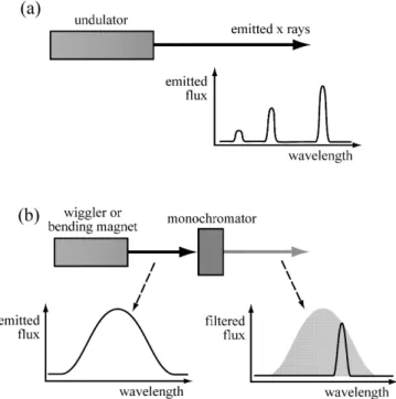
The wavelength of synchrotron X-rays can be adjust-ed over a large spectral range. More specifically (Fig. 1), an undulator emits only specific wavelengths (or, rather, very specific bands of wavelengths) that can be modified by changing the working parameters of the undulator. A bending magnet or a wiggler emits a very broad band of wavelengths from which the desired value can be filtered with a device called a monochromator.
The emission of synchrotron sources is highly coher-ent, producing detectable diffraction and interference phenomena that can be used for imaging. Finally, the emission has a time structure consisting of short pulses separated by longer dark intervals that is used in time-re-solved techniques [2, 3].
All such characteristics can be exploited to image ob-jects in non-conventional ways. The corresponding tech-niques offer advantages and disadvantages with respect to standard radiology. They cannot replace standard radi-ology, but can offer complementary performances and can be quite useful for specialized applications. Further-more, their scope extends beyond medical radiology of live human patients, reaching other radiological tech-niques and applications of great interest to medical and non-medical research and to other fields. Accordingly, our discussion is not strictly limited to diagnostic radiol-ogy.
The technical implementation of these novel imaging approaches is often complex. On the contrary, their con-ceptual basis is quite simple and can be explained in ele-mentary terms: this is the scope of part II of our review. We will discuss, in particular, the following techniques: one-wavelength mammography [4–7, and references cited in 7], two-wavelength digital subtraction angiography [8–12], phase-contrast/edge-enhancement imaging [13–22], dif-fraction-enhanced imaging (DEI) [23, 24] and phase-con-trast microtomography [25–27]. The objective of our pre-sentation is to provide for non-specialized readers a simple picture of each technique: we neither intend to present a detailed report on the results of each technique nor a com-plete list of references. Table 1 presents a summary of the characteristics and applicability of the techniques we dis-cuss.
Techniques based on wavelength selection:
mammography and angiography
The possibility to take radiological images with only one wavelength (monochromatized X-rays: see Fig. 1) in many cases has had an immediate positive impact: the diffused background of the image is reduced with respect to unmonochromatized X-rays. Keeping the X-ray dose constant, this increases the image contrast and quality.
A good example of this positive aspect is provided by mammography. The sources that are typically used for dedicated mammography systems are molybdenum anode X-ray tubes. Their wavelength spectrum con-sists of two strong peaks (“lines”) at approximately 0.63 A° and 0.71 A° (corresponding to photon energies of approximately 19.4 keV and 17.6 keV). These wave-lengths do fall in the optimal spectral region for mam-mography [0.59–0.73 A° (17–21 keV); the actual optimum wavelength and photon energy changes with the breast thickness and density]. However, the two peaks are su-perimposed upon a spectral continuum due to bremsstrah-lung. This continuum extends to wavelengths below the optimal range for mammography, producing a diffused background that deteriorates the image contrast.
A synchrotron source makes it possible to take mam-mographic images with one single wavelength peak, thereby drastically reducing the diffused background [4–7, and references cited in 7]. Furthermore, the wave-length can be tuned to match the optimal wavewave-length for each breast thickness and density.
Synchrotron mammography tests are typically per-formed with a bending magnet source. We mentioned that this source produces a fan-like beam with a narrow vertical angular spread and a broader horizontal spread. The images are taken by vertically scanning the line illu-minated by the beam. The vertical collimation of the beam makes it possible to insert slits behind the breast, thereby further reducing the background.
Fig. 1 Synchrotron sources can provide X-rays of well-defined wavelength (or, rather, narrow bands centered at the desired length). a An undulator emits only very narrow bands of wave-lengths. Individual bands can be selected and the center can be changed by changing the undulator parameters; b a bending mag-net or a wiggler emits instead a broad band from which the de-sired wavelength can be filtered with a monochromator
The notion that synchrotron radiation can drastically reduce the diffused scattering background in mammo-grahy was first tested at the Frascati National Laboratory [4, 5] and then in other facilities [6, 7 and references cit-ed in 7]. These tests were quite positive: the image quali-ty could be preserved while substantially reducing the required dose of X-rays. Conservatively, the scattered-ra-diation reduction is at least by a factor of 100 (and much larger in the phase-contrast geometry explained later), contributing to an overall dose reduction for comparable image quality of 20–60%.
Wavelength tunability is also the essential ingredient of another emerging technique: dichromography [8–12]. This approach is used for coronary angiography during intravenous injection of contrast material.
Synchrotron dichromography (Fig. 2) is a variant of digital subtraction angiography. Rather than being taken
at different times before and after iodine injection, the two images are taken simultaneously at two different wavelengths after iodine injection—for example, by illu-minating the object with two different X-ray beams and detecting them with two different detectors (see later, Fig. 3a). This removes the motion effects of the heart-beat. The wavelengths fall right below and right above the main X-ray absorption edge of iodine (K-edge, at a wavelength of 0.37 A°)—see Fig. 2. The edge corre-sponds to a sharp increase in the iodine-related absorp-tion; thus, the digital subtraction does enhance the io-dine-related features with respect to the other features.
Practically speaking, the sensitivity to iodine can in-crease by two orders of magnitude, drastically reducing the required iodine concentration. The contrast agent can be inserted with a relatively safe intravenous injection procedure. The dilution by a factor ≈50 during the transit Table 1 Summary overview of synchrotron-based radiological techniques
Synchrotron Two-wavelength Phase contrast Diffraction-enhanced Synchrotron
mammography angiography imaging imaging microtomography
(dichromography)
Main imaging Absorption Absorption Phase contrast, Diffraction Absorption,
mechanism(s) (phase contrast, refraction phase contrast,
refraction) refraction
Wavelengths Single Two Single or Single or Single or
broadband broadband broadband
Imaged body Breast tissues Coronaries and Any tissue Any tissue Any tissue
part vother blood essels
Current Phantoms, Live patients Anatomical and Anatomical and Anatomical and
applications anatomical biological biological biological
specimens specimens specimens specimens
Potential Live patients Routine examinations Live patients Live patients Possibly live
applications of live patients patients
Advantages over High contrast Peripheral venous Very high contrast Very high contrast Very high contrast conventional for low dose injection of for lower dose, for lower dose, for low dose, high radiology contrast agent high lateral and high lateral resolution, lateral resolution
time resolution separation of absorption and non-absorption features
Problems Not yet a certified Complicated Non-conventional Non-conventional For phase-contrast: technique for implementation image features, image features, require non-conventional medical use require special special interpretation image features,
interpretation techniques require special
techniques interpretation
techniques Time per 1–10 s Tens of milliseconds <1 ms Down to milliseconds Several seconds
image (for complete
image set) Spatial 30µm Hundreds of microns Better than 1µm Better than 1µm Better than 1µm
resolution (tens of microns
for possible images in vivo)
Three-dimensional No No No No Yes
to the coronary region is in fact compensated by the in-crease in sensitivity to iodine.
Several synchrotron facilities are actively engaged in experimental angiography programs based on dichromography [8–12]. The approach of centers like HASYLAB in Hamburg and Brookhaven [8, 9]— schematically illustrated in Fig. 3a—is based on “line scanning.” A horizontal line of unmonochromatized syn-chrotron radiation goes through a specially designed monochromator that produces two fan-shaped beams with the two desired wavelengths. The optical system is designed so that the two beams cross at the position of the patient’s heart and are separately detected afterwards. Two-dimensional images are obtained by scanning, i.e., by moving the patient vertically across the beam. Images
are acquired during diastole with a sufficient speed of the patient enabling a complete scanning of the heart in less than 250 ms.
The dichromography system of the European Syn-chrotron Radiation Facility (ESRF) in Grenoble [11] is an excellent practical example of this approach. The pa-tient chair moves with a speed of 250 mm/s and the frame rate is 1.4 ms, corresponding to a resolution of 350µm. The typical X-ray dose is 30 mGy per image. In case of failure, emergency systems can shut down the X-ray beams in 10 ms to avoid an excessive dose.
Figure 3b shows one example of the many tests al-ready performed on live patients with this approach. Note that the line-scan technique is automatically insen-sitive to the scattered flux, eliminating the need for an anti-scatter grid. The line detector was in this case a 13-cm-wide ionization chamber filled with KrCO2.
Two-dimensional systems for dichromography were developed in Japan that do not require the scanning pro-cedure. The strategy used at the TRISTAN source [12] is based on a non-conventional elliptical wiggler that pro-duces two slightly diverging beams. As the two beams pass through a specially designed monochromator, they are spread to horizontal and vertical sizes of several cen-Fig. 2 a Digital subtraction angiography: images taken with and
without the contrast agent (iodine) are subtracted from each other, enhancing the iodine-containing features. In the heart the proce-dure is affected by the motion since the two images are taken at different times. b Dichromography: images of the object with the contrast agent are taken simultaneously with two wavelengths above and below the main X-ray absorption edge of the contrast agent. The digital subtraction enhances once again the iodine-con-taining features and is not affected by the motion of the heart
Fig. 3 a Scheme of a system for digital subtraction angiography performed with the dichromography approach (see [8, 9]). b Intra-venous synchrotron angiogram of Intra-venous coronary artery bypass grafts to right coronary artery (CABG-RCA) and marginal branch (CABG-M1) in left anterior oblique projection taken with the NIKOS system at HASYLAB. (Courtesy W.R. Dix—see [8])
timeters, suitable for a two-dimensional angiographic image. The monochromator provides spectral filtering so that the two final beams have the two desired wave-lengths. In addition, scientists in Japan have extensively used monochromatic synchrotron radiation for angiogra-phy without digital subtraction [12].
Extensive tests were performed on synchrotron dichro-mography of human patients, notably at HASYLAB in Hamburg [8]. The future impact of this technique is diffi-cult to assess in light of the general complication in using synchrotrons for radiological analysis, discussed in Part I and in the final chapter. There may also exist the possi-bility to replace iodine with other contrast agents such as gadolinium, whose edge occurs at a wavelength of 0.31 A° , shorter than the iodine edge of 0.37 A°: tests on this approach are underway.
Techniques based on collimation and coherence:
refractive-index imaging
We saw [1] that the emission of a synchrotron source is spread over a very narrow range of angles in the vertical direction; the angular collimation is equally strong in the horizontal direction for wigglers and undulators. Further-more, the source size is very small. A source with strong angular collimation and small size is said to be “spatially coherent.”
Coherent sources of visible light such as the lasers produce diffraction and interference phenomena. The same is true for coherent X-rays. Diffraction and inter-ference can lead to image contrast with non-conventional and rather effective mechanisms [7 and references cited in 7, 13–22], often called (somewhat inaccurately) “phase contrast.”
The coherence-based contrast mechanisms are related to the “refractive index”—the parameter characterizing the phenomena of refraction, interference and diffrac-tion. Such phenomena are negligible in standard radiolo-gy, whose contrast is due to the different X-ray absorp-tion by different parts of the object.
Absorption is in fact an important mechanism in the interaction between the X-rays and the object. However, other mechanisms are also active. Scattering phenomena produce a diffused background that decreases the image quality. Refraction, interference and diffraction can also occur, but their impact on standard radiology is rather limited.
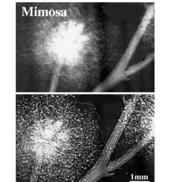
Figure 4, for example, shows the direct comparison of two radiographs of the same objects taken with different experimental conditions that reduce or enhance these non-conventional mechanisms. The bottom image is quite striking, although the X-ray dose was lower than for the top image. Note that the “quality” of the bottom image is due to the enhanced visibility of the edges be-tween different regions.
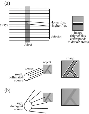
The leading contrast mechanism in Fig. 5 is related to refraction and is schematically illustrated in Fig. 5. Con-sider the case of Fig. 5a in which the X-ray beam passes trough the tapered edge separating two different regions of the object. For the sake of simplification, assume that the two regions have similar X-ray absorption but (slightly) different X-ray refraction. As shown in Fig. 5a, the corresponding beam deviation by the edge region produces a bright-dark fringe pair on the detector—and enhances the visibility of the edge. This is precisely what is observed in the bottom image of Fig. 4. The mecha-nism is somewhat similar to the interaction of visible light with the edge of a glass that makes it more visible than the glass itself.
Figure 5b indicates that a small source size, one of the characteristics of a coherent source, is required to see the refraction-related edge enhancement. If the source is too large, penumbra-like effects wash out the edge enhance-ment. A conventional X-ray source could in principle be converted into a small-size source by using a screen with a pinhole. The side effect, however, is to waste most of the source emission. A synchrotron source is instead nat-urally small (at least in the vertical direction).
The actual geometric conditions for refraction-based edge enhancement are not very stringent [22]: virtually all synchrotron sources built after the mid-1980s are suf-ficiently small. Furthermore, a “monochromatic” (single-wavelength) beam is not required [22]. This eliminates Fig. 4 Direct comparison of two radiographs of the same mimosa flower taken with the absorption contrast of standard radiology (top) and with “phase contrast” (bottom). Image obtained by Ar-felli et al. at the ELETTRA lanboratory in Trieste (see [7, 14, 15])
of water (soft tissues) for 30 keV photon energy deviates from that of vacuum only by one part in 10 billion.
In spite of this, however, refraction can be more ef-fective than absorption in producing image contrast. This is due to two factors. First, X-ray refraction effects and their differences between different materials, although small, are comparatively more pronounced than absorp-tion effects. Second, refracabsorp-tion contrast is a geometrical-ly localized effect: even small X-ray deviations are very effective in producing fringes and in increasing the edge visibility—as seen in the bottom image of Fig. 4. There-fore, edge-enhanced radiography could advantageously complement standard radiographs when low-absorption contrast creates problems.
Examples of images with refraction-induced index
edge enhancement
The practical use of edge-enhancement contrast requires meeting certain experimental conditions [21, 22]. The detectors must have sufficient lateral resolution to reveal the pair of narrow dark-bright fringes. Figure 5a suggests that the fringe width on the detector increases with the object-detector distance. If this distance is too small, the detector resolution (a few microns) is not sufficient to re-veal the fringes, and the edge enhancement is washed out. Absorption contrast dominates in this case: this is in fact how the edge enhancement was suppressed in the top image of Fig. 4.
Figure 5a also indicates that when the detector-object distance becomes too big, the refraction-based fringe pattern spreads and may no longer produce edge en-hancement. In this case, edge enhancement can still oc-cur because of the “diffraction” mechanism discussed later [21].
When all the required experimental conditions are met, refraction-induced edge enhancement can produce rather spectacular results. With an unmonochromatized (“white”) beam, the signal becomes very high and high-quality; detailed images can be obtained on a microscop-ic scale (Fig. 6a). The lateral resolution reaches submi-cron levels suitable for imaging individual cells and is being further improved.
White beams also make it possible to take real-time images with a time resolution that reaches the millisec-ond level and is also rapidly improving. This recently led to the first successful tests of edge-enhanced radiology on live specimens [13, 28]. Figure 6b shows a typical ex-ample of such results: microscopic structures of a live millimeter-size fish.
Time and lateral resolution play a very important role in non-medical applications of radiology [13]. Microradi-ology movies, for example, can solve long-standing issues in material sciences phenomena by direct real-time obser-vation. Figure 7 provides an excellent example: the direct the need for monochromator filtering and the consequent
loss of X-ray flux.
Before presenting some example of edge-enhanced radiographs, we would like to compare refraction-based contrast to the standard absorption contrast of conven-tional radiology. Absorption by soft biological materials is quite low for the relevant wavelengths: this is what en-ables radiology to “see” inside objects. For example, ab-sorption attenuates an X-ray beam with 30 keV photon energy to one-half of the original intensity within ≈19 mm in soft tissues (≈4.3 mm in bones). Small ab-sorption corresponds to small abab-sorption differences between soft tissues. In some cases, the differences are so small that they create image quality problems, for ex-ample, in mammography.
Refraction is also very small for X-rays and so are the differences between materials. The refraction-induced beam deviations are determined by the difference be-tween the refractive index of the material and unity (the refraction index of vacuum). This difference is very small for all materials. For example, the refractive index Fig. 5 a Schematic explanation of the mechanism of edge en-hancement due to refraction in the X-ray image of the tapered edge between two regions of the object. b A small and collimated source certainly gives the edge enhancement; for a large and di-vergent source, the enhancement may be washed out by penumbra effects
detection of an almost incredible phenomenon in the elec-trodeposition of thin metal coatings [29]. As clearly seen in the radiology movie frames, the electrodeposition pro-cess creates hydrogen bubbles at the substrate-coating in-terface. The metal coating grows on the fast-developing bubbles; as these evaporate, spherical voids are left that fi-nally explain a common kind of coating defects.
Diffraction phenomena in edge enhancement
Our treatment of edge enhancement was so far limited to simple refraction phenomena [22]. Reality is a bit more complicated. First of all, the edges between different ob-ject regions do not typically have simple profiles like that of Fig. 5a. This is a source of complications, but also, potentially, of additional information.
Our analysis was also oversimplified from the point of view of fundamental optics. A complete modeling would Fig. 6 Examples of images with refraction-induced edge enhance-ment [13]. a Microscopic features of an ant leg are sharply visible in this edge-enhanced white-beam image. b One of the first tests on live organisms: bone microstructure of a live millimeter-size fish
Fig. 7 Real-time edge-enhanced microradiology applied to mate-rial science. The two frames captured from a radiology movie [28] reveal a very surprising phenomenon during a metal coating pro-cedure: the metal grows on gas bubbles forming on the substrate during the deposition process
guments [22]. Imagine (Fig. 8a) an opaque object with sharp, non-tapered edges illuminated by a point source of visible light with reasonably well-defined wavelength. It is well known that this illumination produces diffrac-tion fringes at the edge; this is the classical phenomenon known as “Fresnel edge diffraction.”
Consider now (Fig. 8b) the equivalent phenomenon for X-rays: a coherent synchrotron X-ray beam illumi-nating a sharp edge between two object regions. There is, in this case, no “opaque” object since both regions of the system are partly transparent to X-rays. Nevertheless, edge diffraction fringes are produced by the coherent beam—see Fig. 8c. Such diffraction fringes do produce edge enhancement as refraction did for tapered edges.
Note that our discussion of Fig. 8b hypothesized a “sharp edge.” Specifically, an infinitely sharp edge can produce diffraction as in Fig. 8b, but it cannot produce edge enhancement by refraction. In a more realistic pic-ture, the object edges are not infinitely sharp, and both refraction and diffraction effects can coexist. We saw that refraction effects tend to decrease at large detector-object distances: this property can be used to enhance diffraction effects relative to refraction effects or vice versa [21].
Practically speaking, refraction effects dominate the vast majority of edge-enhanced radiographs. In the rela-tively few cases when they are visible, diffraction effects can have both a positive and a negative impact on the image analysis. On one hand, they complicate the images since each edge corresponds to a series of fringes rather than just to a pair of dark-bright fringes. On the other hand, the edge diffraction fringes potentially carry much more information than the refraction fringes. The diffrac-tion fringes are theoretically equivalent to a hologram and could lead to holographic reconstruction. It is doubt-ful, however, that this approach could be of interest for medical radiology, whereas it could find applications in other branches of radiology.
Diffraction-enhanced imaging
We have so far separately treated the contrast related to the refractive index and the conventional absorption con-trast. This is not realistic: in practical cases, both mecha-nisms are active and the overall contrast is due to their interplay. An accurate analysis of the images of Figs. 4, 6, 7, 8 reveals indeed that refraction (and/or diffraction) contrast are also accompanied by absorption contrast.
The interplay of absorption and refraction may some-times complicate the image analysis. Theoretical optics, however, offers a very elegant method to separate the two mechanisms: the “diffraction-enhanced imaging,” or DEI [23].
As schematically shown in Fig. 9a, a “Bragg filter” is placed after the specimen and before the detector. The require a detailed treatment of the X-ray propagation
,in-cluding phenomena such as interference and diffraction. Without theoretical complications, we can still under-stand the most important consequences with simple ar-Fig. 8 Edge enhancement by Fresnel edge diffraction. a An opaque object illuminated by visible light of well-defined wave-length emitted by a point-source produces diffraction fringes. b A similar phenomenon occurs when coherent X-rays illuminate a sharp edge between two different regions of an object. c Diffrac-tion fringes are indeed clearly visible in this radiograph of two crossed optical fibers (horizontal and vertical), specifically the fringes are present both for the outer edges between the horizontal fiber and vacuum and for the edges between the inner and outer parts of this fiber. On the contrary, no fringes can be seen for the vertical fiber. The reason is that the synchrotron X-rays beam— emitted by a bending magnet—was coherent only in the vertical direction perpendicular to the horizontal fiber edges. This in turn is due to the fact that for a bending magnet source, size and angu-lar spread are small only in the vertical direction
Bragg filter is a crystal that drastically reduces the inten-sity of X-rays traveling in all directions except its “Bragg reflection.” This sharp direction filtering already improves the radiographs by suppressing the diffused background.
The DEI technique, however, exploits the direction of filtering in far a more sophisticated way. Two images are sequentially taken with the Bragg filter direction slightly tilted at two symmetric angles with respect to the beam direction. A mathematical procedure is then applied to combine the pixels of the two images. This procedure yields two new images, one only due to absorption con-trast and the other only to refractive-index concon-trast [23, 24]—see Fig. 9b.
Other clever ways have been developed to enhance the effects of the different contrast mechanisms [2]—and more undoubtedly will be invented in the future. Such approaches have not yet reached the medical radiology community, except for a few specialists. This is regret-table, since a closer collaboration between synchrotron radiation experts and medical-radiology experts could fine-tune the development of new techniques, as hap-pened in the case of DEI.
Tomography techniques
An increasingly important role in synchrotron radiology is played by tomography reconstruction [25–27]. Similar to standard medical tomography, this approach consists of taking images for many different object orientations and then using powerful computer-based mathematical
meth-ods to reconstruct object slices or other views. The use of synchrotron radiation makes it possible to extend com-puter-assisted tomography to the micron and submicron scale, with substantial impact on radiological research.
This impact is enhanced by the use of refraction-based contrast. The enhancement because of refraction improves the edge visibility and makes it possible to re-duce the X-ray dose: this is important for the multiple image taking required for tomography. The correspond-ing technique is called “phase contrast microtomogra-phy” [25–27].
The tomographic reconstruction is still affected by some difficulties related to the phase-based contrast mechanism. These problems notwithstanding, synchro-tron phase contrast microtomography has already pro-duced very spectacular results, and medical applications can be foreseen for special diagnostic problems.
Outlook
Part I of our review [1] already discussed in realistic terms the advantages and disadvantages of using syn-chrotron sources for medical applications and the corre-sponding outlook. We discussed, in particular, issues concerning the infrastructure, the construction and oper-ating costs and the logistics and the inconvenience of us-ing a centralized facility. We thus limit our discussion here to the novel radiology techniques and to the corre-sponding instrumentation.
Synchrotron-based radiology is very far from the end of its development: the potential has been only marginal-ly exploited so far [2]. Specialized beamlines fulmarginal-ly dedi-cated to radiology tests accelerate this development.
Particular attention is devoted to the X-ray detectors. Standard films or ionization chambers are suitable for detecting synchrotron-emitted X-rays. However, most of the techniques discussed above are enhanced by the use of digital detectors such as CCD detectors with high lat-eral resolution, fast readout and suitable computer-based reading systems. For microradiography, specialized ap-proaches have been developed [13] based on photoelec-tron emission microscopes (PEEMs).
We have seen that wavelength tunability is one of the strongest features of synchrotron sources. Other develop-ing approaches besides those discussed above attempt to make a more extensive use of this feature [30]. We saw that images taken at different wavelengths can reveal the localization of a given chemical element such as iodine. This is possible, in principle, for any element with an X-ray absorption edge in the accessible region of wave-lengths. In practice, however, this procedure was confined so far to strong X-ray absorbers like iodine or gadolinium.
Synchrotron X-rays and “phase contrast” could over-come this limitation and make it possible to observe the spatial distribution of other elements. This is based on a Fig. 9 a Scheme of the diffraction-enhanced imaging (DEI)
ap-proach [23]. b Example of DEI result: (left) standard radiograph of a mouse heart; (center and right) processed DEI image corre-sponding to absorption and refractive-index contrast (see [24], pic-ture courtesy of the British Journal of Radiology)
fundamental optical property: an X-ray absorption edge must correspond to a rapid change of the refractive index with the wavelength [2]. Thus, refraction-enhanced imag-es taken at different wavelengths close to an absorption edge could yield information on the spatial distribution of the corresponding chemical element. Practical tests of this hypothesis are underway with preliminary success [30].
In more general terms, the biggest challenge for syn-chrotron-based radiology is medical validation after ex-tensive tests on human patients. This validation must demonstrate that new techniques are substantially better than standard radiology in their specific domains of ap-plication. The advantages must be strong enough to justi-fy overcoming the technical difficulties of using a syn-chrotron facility.
So far, extensive medical validation tests have only been performed for synchrotron coronary angiography. The results have been impressive and the advantages of synchrotron-based angiography clearly demonstrated. However, the key issue is not yet resolved: the experts are not unanimous about the adoption of synchrotron an-giography as a routine analysis.
Medical validation tests are being developed for other techniques such as “phase contrast” synchrotron mam-mography. Actual tests on human patients are expected to
begin at the Elettra synchrotron in Trieste within the next 12–18 months, the main remaining obstacle being the le-gal requirements. The results will clarify the basic ques-tion: will synchrotron radiology remain a “niche” activity or will it join the mainstream of medical radiology?
A mainstream role would, of course, become easier if the technical difficulties could be simplified—in particu-lar, by developing compact sources suitable for a hospi-tal environment. As mentioned in part I, the Compton-backscattering sources [31] are most promising. Al-though generally inferior to storage rings, they would be suitable for virtually all synchrotron radiology tech-niques—and would be much smaller, cheaper and sim-pler to operate. This, together with the demonstration of their superiority in specific cases, might be the key fac-tor for the future role of synchrotron radiology.
Acknowledgments We are very grateful to Giuliana Tromba for several comments and practical information on phase contrast, mammography and DEI. Our work in synchrotron radiology is performed at the PLS facility in Korea, at SRRC-Taiwan, at the Argonne APS and at Elettra in Trieste. Our research programs in this domain are supported by the National Science Council of Taiwan, by the SKORE-A Program, by KOSEF, by the Fonds Na-tional Suisse de la Recherche Scientifique, by the Ecole Polytech-nique Fedérale de Lausanne and by the NICOP Program (N00014-99-1-0814) of the US Office of Naval Research.
References
1. Margaritondo G, Meuli R (2003) Syn-chrotron radiation in radiology. Novel X-ray sources. Eur Radiol 13:2533-2541
2. Margaritondo G (2003) Elements of synchrotron radiation for chemistry, biology and medical research. Oxford University Press, New York
3. Margaritondo G (1988) Introduction to synchrotron radiation. Oxford University Press, New York
4. Burattini E, Gambaccini M, Marziani M, Rimondi O, Indovina PL, Pocek M, Simonetti G, Benassi M, Tirelli C, Passariello R (1992) X-ray mammogra-phy with synchrotron radiation. Rev Sci Instrum 63:638–640 5. Burattini E, Cossu E, Di Maggio C,
Gambaccini M, Indovina PL, Marziani M, Pocek M, Simeoni S, Simonetti G (1995) Mammography with synchro-tron radiation. Radiology 195:239–244 6. Johnston RE, Washburn D, Pisano E,
Thomlinson WC, Chapman D, Gmur NF, Zhong Z, Sayers D (1995) Mammography phantom studies with synchrotron radiation. Radiology 197:221
7. Arfelli F, Bonvicini V, Bravin A, Cantatore G, Castelli E, Dalla Palma L, Di Michiel M, Fabrizioli M, Longo R, Menk RH, Olivo A, Pani S, Pontoni D, Poropat P, Prest M, Rashevsky A, Ratti M, Rigon L, Tromba G, Vacchi A, Vallazza E (2000) Mammography with synchrotron radiation: phase detection techniques. Radiology 215:286–293 8. Dix WR, Kupper W, Dill T, Hamm
CW, Job H, Lohmann M, Reime B, Ventura R (2003) Comparison of intra-venous coronary angiography using synchrotron radiation with selective coronary angiography. J Synchrotron Radiat 10:219–227
9. Thomlinson W, Gmür N, Chapman D, Garrett R, Lazarz N, Moulin H, Thompson AC, Zeman HD, Brown GS, Morrison J, Reiser P, Padmanabahn V, Ong L, Green S, Giacomini J, Gordon H, Rubenstein E (1992) First operation of the medical-research facility at the NSLS for coronary angiography. Rev Sci Instrum 63:625–628
10. Kolesnikov KA, Kulipanov GN, Kuzin MV, Mezentsev NA, Nesterov SI, Pindyurin VF, Dragun GN, Rozenberg OA, Zelentsov EL (1995) Preliminary-results of an animals lymphatic-system study at the angiography station of the Vepp-3 storage-ring. Nucl Instrum Methods A 359:364–369
11. Elleaume H, Fiedler S, Esteve F, Bertrand B, Charvet AM, Berkvens P, Berruyer G, Brochard T, Le Duc G, Nemoz C, Renier M, Suortti P, Thomlinson W, Le Bas JF (2000) First human transvenous coronary angiogra-phy at the European Synchrotron Radiation Facility. Phys Med Biol 45:L39–L43
12. Takeda T, Itai Y, Hyodo K, Ando M, Akatsuka T, Uyama C (1998) Medical applications with synchrotron radiation in Japan. J Synchrotron Radiat 5:326–332
13. Hwu Y, Tsai Wen-Li, Groso A, Margaritondo G, Je Jung Ho (2002) Coherence-enhanced synchrotron radi-ology: simple theory and practical ap-plication. J Phys D35:R105–R120 14. Arfelli F, Assante M, Bonvicini V, Bravin A, Cantatore G, Castelli E, Dalla Palma L, Di Michiel M, Longo R, Olivo A, Pani S, Pontoni D, Poropat P, Prest P, Rashevsky A, Tromba G, Vacchi A, Vallazza E, Zanconati F (1998) Low-dose phase contrast X-ray medical imaging. Phys Med Biol 43:2845–2852
15. Olivo A, Castelli E, Arfelli F, Bravin A, Pani S, Tromba G (1998) Phase contrast and diffraction enhanced im-aging with synchrotron radiation: a feasibility study for mammographic applications. Radiology 209:608–608 16. Snigirev A, Snigireva I, Kohn V,
Kuznetsov S, Schelokov I (1995) On the possibilities of X-ray phase contrast microimaging by coherent high-energy synchrotron radiation. Rev Sci Instrum 66:5486–5492
17. Pogany A, Gao D, Wilkins SW (1997) X-ray phase-contrast radiography. Rev Sci Instrum 68:2774–2782 18. Wilkins SW, Gureyev TE, Gao D,
Pogany A, Stevenson AW (1996) Phase-contrast imaging using polychromatic hard X-rays. Nature 384:335–338
19. Takeda T, Momose A, Wu J, Yu Q, Zeniya T, Thet-Thet-Lwin, Yoneyama A, Itai Y (2002) Vessel imaging by interferometric phase-contrast X-ray technique. Circulation 105:1708–1712
20. Cloetens P, Pateyron-Salomé M, Buffière JY, Peix G, Baruchel J, Peyrin F, Schlenker M (1997) Observation of microstructure and damage in materials by phase sensitive radiography and tomography. J Appl Phys
81:5878–5886
21. Margaritondo G, Tromba G (1999) Coherence-based edge diffraction sharpening of X-ray images: a simple model. J Appl Phys 85:3406–3408 22. Hwu Y, Hsieh HH, Lu MJ, Tsai WL,
Lin HM, Goh WC, Lai B, Je JH, Kim CK, Noh DY, Youn HS, Tromba G, Margaritondo G (1999) Coherence-enhanced synchrotron radiology: refraction vs. diffraction mechanisms. J Appl Phys 86:4613–4618
23. Chapman D, Thomlinson W, Johnston RE, Washburn D, Pisano E, Gmur N, Zhong Z, Menk R, Arfelli F, Sayers D (1997) Diffraction-enhanced X-ray im-aging. Phys Med Biol 42:2015–2025 24. Lewis RA, Hall CJ, Hufton AP, Evans
S, Menk RH, Arfelli F, Rigon L, Tromba G, Dance DR, Ellis IO, Evans A, Jacobs E, Pinder SE, Rogers KD (2003) X-ray refraction effects: application to the imaging of biological tissues. Br J Radiol 76:301–308 25. Spanne P, Raven C, Snigireva I,
Snigirev A (1999) In-line holography and phase-contrast microtomography with high energy X-rays. Phys Med Biol 44:741–749
26. Momose A, Takeda T, Itai Y, Hirano K (1996) Phase-contrast X-ray computed tomography for observing biological soft tissues. Nat Med 2:473–475 27. Stampanoni M, Borchert G, Abela R,
Ruegsegger P (2002) Bragg magnifier: a detector for submicrometer X-ray computer tomography. J Appl Phys 92:7630–7635
28. Lee K-H, Hwu Y, Je JH, Tsai W-L, Choi E-W, Kim Y-C, Kim H-J, Seong J-K, Yi S-W (2002) Synchrotron radia-tion imaging of internal structures in live animals. Yonsei Med J 43:25–30 29. Tsai WL, Hsu PC, Hwu Y, Chen CH, Chang LW, Je JH, Lin HM, Groso A, Margaritondo G (2002) Building on bubbles in metal electrodeposition. Nature 417:139–139
30. Groso A, Margaritondo G, Hwu Y, Tsai W-L, Je JH, Lai B (2002) Dispersive coherence-enhanced radiology: experi-mental test and modeling. Appl Phys Lett 81:3888–3892
31. Carroll FE (2002) Tunable monochro-matic X-rays: a new paradigm in medi-cine. Am J Roentgenol 179:583–590
![Fig. 3 a Scheme of a system for digital subtraction angiography performed with the dichromography approach (see [8, 9])](https://thumb-eu.123doks.com/thumbv2/123doknet/14850061.629306/4.892.440.821.102.504/fig-scheme-digital-subtraction-angiography-performed-dichromography-approach.webp)
![Fig. 7 Real-time edge-enhanced microradiology applied to mate- mate-rial science. The two frames captured from a radiology movie [28]](https://thumb-eu.123doks.com/thumbv2/123doknet/14850061.629306/7.892.77.402.86.1029/real-enhanced-microradiology-applied-science-frames-captured-radiology.webp)