HAL Id: hal-03009287
https://hal.archives-ouvertes.fr/hal-03009287
Submitted on 17 Nov 2020
HAL is a multi-disciplinary open access
archive for the deposit and dissemination of
sci-entific research documents, whether they are
pub-lished or not. The documents may come from
teaching and research institutions in France or
abroad, or from public or private research centers.
L’archive ouverte pluridisciplinaire HAL, est
destinée au dépôt et à la diffusion de documents
scientifiques de niveau recherche, publiés ou non,
émanant des établissements d’enseignement et de
recherche français ou étrangers, des laboratoires
publics ou privés.
Polarimetric remote sensing of atmospheric aerosols:
Instruments, methodologies, results, and perspectives
O. Dubovik, Zhengqiang Li, Michael Mishchenko, Didier Tanré, Yana Karol,
Bojan Bojkov, Brian Cairns, David Diner, W. Reed Espinosa, Philippe
Goloub, et al.
To cite this version:
O. Dubovik, Zhengqiang Li, Michael Mishchenko, Didier Tanré, Yana Karol, et al..
Polarimet-ric remote sensing of atmosphePolarimet-ric aerosols: Instruments, methodologies, results, and perspectives.
Journal of Quantitative Spectroscopy and Radiative Transfer, Elsevier, 2019, 224, pp.474 - 511.
�10.1016/j.jqsrt.2018.11.024�. �hal-03009287�
Journal of Quantitative Spectroscopy & Radiative Transfer 224 (2019) 474–511
ContentslistsavailableatScienceDirect
Journal
of
Quantitative
Spectroscopy
&
Radiative
Transfer
journalhomepage:www.elsevier.com/locate/jqsrt
Review
Polarimetric
remote
sensing
of
atmospheric
aerosols:
Instruments,
methodologies,
results,
and
perspectives
Oleg Dubovik
a,∗, Zhengqiang Li
b,∗, Michael I. Mishchenko
c, Didier Tanré
a, Yana Karol
d,
Bojan Bojkov
e, Brian Cairns
c, David J. Diner
f, W. Reed Espinosa
g,h, Philippe Goloub
a,
Xingfa Gu
b, Otto Hasekamp
i, Jin Hong
j, Weizhen Hou
b, Kirk D. Knobelspiesse
h,
Jochen Landgraf
i, Li Li
b, Pavel Litvinov
d, Yi Liu
k, Anton Lopatin
d, Thierry Marbach
e,
Hal Maring
l, Vanderlei Martins
g, Yasjka Meijer
m, Gennadi Milinevsky
n, Sonoyo Mukai
o,
Frederic Parol
a, Yanli Qiao
j, Lorraine Remer
g, Jeroen Rietjens
i, Itaru Sano
p, Piet Stammes
q,
Snorre Stamnes
r, Xiaobing Sun
j, Pierre Tabary
s, Larry D. Travis
c, Fabien Waquet
a, Feng Xu
f,
Changxiang Yan
t, Dekui Yin
ua Laboratoire d’Optique Atmosphérique, CNRS/Université Lille, Villeneuve d’Ascq, France
b State Environmental Protection Key Laboratory of Satellite Remote Sensing, Institute of Remote Sensing and Digital Earth, Chinese Academy of Sciences, Beijing, China
c NASA Goddard Institute for Space Studies, New York, NY, USA d GRASP-SAS, Villeneuve d’Ascq, France
e European Organisation for the Exploitation of Meteorological Satellites (EUMETSAT), Darmstadt, Germany f Jet Propulsion Laboratory, California Institute of Technology, Pasadena, CA, USA
g University of Maryland, Baltimore County, Baltimore, USA h NASA Goddard Space Flight Center, Greenbelt, MD, USA
i SRON Netherlands Institute for Space Research, Utrecht, The Netherlands
j Anhui Institute of Optics and Fine Mechanics, Chinese Academy of Sciences, Hefei, China k Institute of Atmospheric Physics, Chinese Academy of Sciences, Beijing, China
l Earth Science Division, Science Mission Directorate, NASA Headquarters, Washington, DC, USA m European Space Agency (ESA), Keplerlaan 1, 2201 AZ Noordwijk, The Netherlands n Taras Shevchenko National University of Kyiv, Kyiv, Ukraine
o Kyoto College of Graduate Studies for Informatics, Kyoto, Japan p Faculty of Science and Engineering, Kindai University, Osaka, Japan q Royal Netherlands Meteorological Institute, De Bilt, The Netherlands r NASA Langley Research Center, Hampton, VA, USA
s CNES–Direction de l’Innovation des Applications et de la Science (DIA), Toulouse, France
t Changchun Institute of Optics, Fine Mechanics and Physics, Chinese Academy of Sciences, Changchun, China u Shanghai Institute of Technical Physics, Chinese Academy of Sciences, Shanghai, China
a
r
t
i
c
l
e
i
n
f
o
Article history:
Received 15 November 2018 Accepted 18 November 2018 Available online 4 December 2018
Keywords: Aerosols Remote sensing Polarimetry Radiative transfer Retrieval algorithms
a
b
s
t
r
a
c
t
Polarimetryisone ofthemostpromisingtypesofremotesensingforimprovedcharacterizationof at-mospheric aerosol.Indeed,aerosolparticlesconstitute ahighly variable atmosphericcomponent char-acterizedbyalargenumberofparametersdescribingparticlesizes,morphologies(includingshapeand internal structure),absorption and scatteringproperties,amounts, horizontal and verticaldistribution, etc.Reliablemonitoringofalltheseparametersisverychallenging,andthereforetheaerosoleffectson climateandenvironmentareconsideredtobeamongthemostuncertainfactorsinclimateand environ-mentalresearch.Inthisregard,observationsthatprovideboththeangulardistributionofthescattered atmosphericradiation aswell asits polarizationstateatmultiplewavelengths covering theUV–SWIR spectralrangecarrysubstantialimplicitinformationontheatmosphericcomposition.Therefore,high ex-pectations inimprovingaerosolcharacterizationare associatedwithdetailedpassivephotopolarimetric observations.
∗ Corresponding authors.
E-mail addresses: oleg.dubovik@univ-lille.fr (O. Dubovik),lizq@radi.ac.cn (Z. Li). https://doi.org/10.1016/j.jqsrt.2018.11.024
O. Dubovik, Z. Li and M.I. Mishchenko et al. / Journal of Quantitative Spectroscopy & Radiative Transfer 224 (2019) 474–511 475
Thecriticalneedtousespace-bornepolarimetryfor globalaccuratemonitoringofdetailedaerosol propertieswasfirstarticulatedinthelate1980sandearly1990s.Bynow,severalorbitalinstrumentshave alreadyprovidedpolarizationobservationsfromspace,andanumberofadvancedmissionsarescheduled forlaunchinthecomingyearsbyinternationalandnationalspaceagencies.Thefirstandmostextensive recordofpolarimetricimagerywasprovidedbyPOLDER-I,POLDER-II,andPOLDER/PARASOLmulti-angle multi-spectralpolarizationsensors.PolarimetricobservationswiththePOLDER-likedesign intendedfor collectingextensivemulti-angularmulti-spectralmeasurementswillbeprovidedbyseveralinstruments, suchastheMAI/TG-2,CAPI/TanSat,andDPC/GF-5sensorsrecentlylaunchedbytheChineseSpaceAgency. Instruments suchas the3MI/MetOp-SG, MAIA, SpexOne and HARP2onPACE, POSP,SMAC, PCF, DPC– Lidar,ScanPolandMSIP/Aerosol-UA,MAP/CopernicusCO2Monitoring,etc.areplannedtobelaunchedby differentspaceagenciesinthecomingdecade.Theconceptsofthesefutureinstruments,theirtechnical designs,andtheaccompanyingalgorithmdevelopmenthavebeentestedintensivelyandanalyzedusing diverseairborneprototypes.Certainpolarimetriccapabilitieshavealsobeenimplementedinsuchsatellite sensorsasGOME-2/MetOpandSGLI/GCOM-C.
Anumberofaerosolretrieval productshavebeen developedbasedontheavailablemeasurements and successfully used fordifferent scientific applications.However, the completenessand accuracy of aerosoldataoperationallyderivedfrompolarimetrydonotyetappeartohavereachedtheaccuracylevels impliedbytheoreticalsensitivitystudiesthatanalyzedthepotentialinformationcontentofsatellite po-larimetry.Asaresult,thedatasetprovidedbyMODISisstillmostfrequentlyusedbythescientific com-munity,yetthissensor hasneitherpolarimetric normulti-angularcapabilities.Admittedlypolarimetric multi-angularobservationsarehighlycomplexandhaveextrasensitivitiestoaerosolparticlemorphology, verticalvariabilityofaerosolproperties,polarizationofsurfacereflectance,etc.Assuch,theynecessitate state-of-the-artforwardmodelingbasedonfirst-principlesphysicswhichremainsrare,andconventional retrievalapproachesbasedonlook-uptablesturnouttobeunsuitable tofullyexploit theinformation implicitinthemeasurements.Severalnew-generationretrievalapproacheshaverecentlybeenproposed toaddressthesechallenges. Thesemethodsuseimprovedforwardmodelingofatmospheric(polarized) radiancesandimplementasearchinthecontinuousspaceofsolutionsusingrigorousstatistically opti-mizedinversions.Suchtechniquesprovidemoreaccurateretrievalsofthemainaerosolparameterssuch asaerosolopticalthicknessandyieldadditionalparameterssuchasaerosolabsorption.However,the op-erationalimplementationofadvancedretrieval approaches generallyrequires asignificantextraeffort, andtheforward-modelingpartofsuchretrievalsstillneedstobesubstantiallyimproved.
Ground-basedpassivepolarimetricmeasurementshavealsobeenevolvingoverthepastdecade. Al-thoughpolarimetryhelpsimproveaerosolcharacterization,especiallyofthefineaerosolmode,the op-eratorsofmajorobservationalnetworkssuchasAERONETremainreluctanttoincludepolarimetric mea-surements aspart of routine retrievalsowing totheir highcomplexity and notable increasein effort requiredtoacquireandinterpretpolarizationdata.
Inadditiontoremote-sensingobservations,polarimetriccharacteristicsofaerosolscatteringhavebeen measuredinsituaswellasinthelaboratoryusingpolarnephelometers.Suchmeasurementsconstitute directobservationsofsinglescatteringwithnocontributionsfrommultiplescatteringeffectsand there-foreprovideuniquedataforthevalidationofaerosolopticalmodelsandretrievalconcepts.
Thisarticleoverviewstheabove-mentionedpolarimetricobservations,theirhistoryandexpected de-velopments,and the stateof resultingaerosolproducts. It alsodiscusses the main achievements and challengesintheexploitationofpolarimetryfortheimprovedcharacterizationofatmosphericaerosols.
© 2018TheAuthors.PublishedbyElsevierLtd. ThisisanopenaccessarticleundertheCCBYlicense.(http://creativecommons.org/licenses/by/4.0/)
1. Introduction
Overthepastfivedecades,remotesensinghasbeenextensively exploitedforderivingtheglobaldistributionofradiativeproperties oftheEarth’satmosphereandsurface.Yetthepotentialof improv-ing thevolume andaccuracyofretrievedinformation and expec-tations of further evolution of remote-sensingtechniques remain high[1,2].Inparticular,futureprogressinthecomprehensive char-acterization of atmospheric aerosolproperties isoften associated withtheadvancementofmulti-angularmulti-spectralpolarimetry
[3].
Aerosolparticlesrangefromafewtenthstoseveraltensof mi-crometers insize. Particlesofsuch dimensionsare usually invisi-bletothehumaneye,howevertheyefficientlyinteractwithsolar radiationandaffectstronglyitsdistributionthroughoutthe atmo-sphere aswell asinfluence thetotal atmospheric energybudget, atmospheric visibility, andclimate dynamics.They also have im-portant impacts on the environment, air quality and safety, and otheraspectsofhumanlife.
Yet accounting for the effects of aerosol particles is very
dif-constituents.Forexample,ithaswidelybeenrecognized that the lingeringuncertaintyintheknowledgeofaerosolpropertiesdrives the global climate change estimation uncertainly (e.g., IPCC1 re-ports[4,5]).Indeed,aerosolis amixtureof smallparticlesof dif-ferentsizes,shapes, morphologies,andcompositions.Thephysical andchemical, aswell astheresultingopticalandradiative, prop-erties of such mixtures can be quite complex and must be de-scribedbyalargenumberofparameters.Inaddition,aerosol prop-erties exhibit a very strong temporal and spatial variability. For example,the loadingand composition ofaerosol particles overa 10× 10kmscenecanchangedramaticallywithinjusthalfanhour, that is, much faster and much stronger than most atmospheric gases. Therefore,fora reliable characterizationof aerosol, alarge numberofaerosolparametersneedtoberetrievedsimultaneously atratherfinetemporalandspatialscales.
Multi-angular multi-spectral polarimeters are widely consid-eredasinstrumentsthat can providemost oftherequisite infor-mation about global and regional properties of aerosols. Indeed,
476 O. Dubovik, Z. Li and M.I. Mishchenko et al. / Journal of Quantitative Spectroscopy & Radiative Transfer 224 (2019) 474–511
simultaneousspectral,angular, andpolarimetric measurements of atmospheric radiation should maximize the sensitivity of obser-vationstodetailedaerosolproperties.Numeroustheoretical stud-ieshaveconcludedthat polarimetry isanapproach thatcan pro-vide accurate characterizationofaerosols withthe detailand ac-curacysufficientformanyimportantapplications.Specifically,the studiesbyMishchenkoandTravis [6,7],Mishchenkoetal.[8],and HasekampandLandgraf[9,10] wereamongthefirsttosuggestthat aerosol amount, type, and other detailed properties such as the abilityto absorb solarradiation can be derived frompolarimetry withanaccuracysufficientfortherequisitereductionofthe uncer-taintyinaerosolclimateforcing[11].Anumberofother indepen-dentanalyses havesupportedtheconclusionaboutthestrong po-tentialofpolarimetricobservationsforreliablemonitoringof vari-ousaerosolparameters(e.g.,Refs.[12,13],etc.).
The criticalneedto usespace-bornepolarimetryforglobal ac-curate monitoring of detailedaerosol properties wasfirst articu-lated in the late 1980s and early 1990s [14,15] based on previ-oustremendoussuccessesofplanetarypolarimetry(see,e.g.,Refs.
[16–20]). As a consequence, the EOSP was includedin the NASA EOSpayload.Unfortunately,thisinstrumentwaslaterdescoped be-causeofbudgetconstraintsandexpectationsthatradiometerslike MODISandMISRwouldprovidetherequisiteaerosolinformation. Routine orbital polarimetric observations of the terrestrial at-mospherestartedin1996 withthelaunch ofthePOLDER instru-ment[21] ontheADEOS-1platform.Thisobservationalrecordwas continued by two subsequent POLDER instruments launched on theADEOS-2andPARASOLsatelliteplatforms(e.g.,seeRef.[22]).A dedicatedaerosolpolarimeter,theNASAAPS[23],waslostduring unsuccessfullaunchin2011.Quiterecently,severalsatellite instru-ments with polarimetric capabilities have been deployed by na-tionalspaceagencies.Anumberoffuturesatellitepolarimetric in-strumentsandmissions are plannedandscheduled forlaunch in thecomingdecade.
Many airborne versions oforbital polarimeters havebeen de-velopedanddeployedduringfieldcampaignstotestandimprove theconcept ofpolarimetricremote sensing. Polarimetric observa-tionsofaerosolpropertieshavealsobeenimplementedby ground-basedradiometernetworks.Inaddition,severalinsituand labora-torypolar-nephelometer systemshavebeendesignedforaccurate measurementsofspectral,angular,andpolarimetriccharacteristics oflightsinglyscatteredbyaerosolparticles.
Nevertheless, the overall volume of polarimetric observations oftheatmosphere remains smallcompared tothat of photomet-ric observations. Furthermore, the currently available polarimet-ric observationsare mostly considered asuseful datasets for un-derstandingthepotential of polarimetry andfordesigning future missions ratherthan asan indispensable source ofaerosol infor-mation forspecific climatological and environmentalapplications
[13]. Thissituationisundoubtedly theresultof thegeneral com-plexity ofpolarimetric observations and theory. Firstly, obtaining consistent,highlyaccurate,simultaneousmulti-angular polarimet-ric observations ina sufficiently wide spectral rangeis a techni-callydifficulttaskrequiringsubstantialeffortsfordesigning, build-ing,andimplementingadequate detectionsystems.Secondly,and probablymorefundamentally, the interpretationof multi-angular multi-spectral polarimetric data is quite challenging. Polarimetry ishighly sensitive to a large numberof atmosphericparameters, andaccountingadequatelyforallthesesensitivitiesintheretrieval algorithm is very demanding, especially in satellite applications where large volumes of data need to be processed in near-real timeorwithaminimaldelay.Notsurprisingly,applicationsof con-ventionalalgorithmtypesthatperformedwell withintensity-only satellitedata(e.g.,Refs.[24,25])topolarimetricobservationsfailed to realize the significant advantages of aerosol polarimetry [26]. Therefore,theneed todevelop more robust algorithmsfor
deriv-ingaerosolpropertiesfrompolarimetryhasbeenclearlyidentified by the satellite community. As aresult, severalsuch highly opti-mizedalgorithms havebeendevelopedanddemonstratedto pro-videenhancedaerosolretrievalsfromsatellitepolarimetry[27–31]. Yetitremains clearthatadditionaleffortsareneededforthe un-derstandingandutilizationofthefullpotentialofaerosolretrievals frompolarimetricobservations.Asitcurrentlystands,satellite po-larimetryremainsan underexploitedarea ofaerosolremote sens-ingwhichrequiresmoreattentionandinvestmentfromtheremote sensingcommunity sinceadvancements in thisarea are likely to driveprogressinaerosol(andoverallatmospheric)monitoring.
The mainobjectiveof thispaperisto supportongoing efforts aimedattheadvancementofaerosolpolarimetrybygathering de-tailed information about the available and planned polarimetric observationsandprovidingreferencesto othersupplementary in-formationontheexistingdataproductsandtheirdistribution.We alsosummarizerecentprogressinthe areasofforwardmodeling andretrievalalgorithmdevelopment,outlinethemostchallenging aspectsofpolarimetricretrievals,anddiscusspotentiallypromising ideasforfurtheradvancementofpolarimetricretrieval methodolo-gies.Owingtoitsnature,thispapercontainsalargenumberof ref-erences(Refs.[1–277]).Assuch,itcanalsobeconsidereda repre-sentativedatabaseofpublicationsrelevanttopolarimetric remote sensingoftroposphericaerosols.
2. Polarimetric observations
Thispaperisprimarilyfocusedonpassivepolarimetric observa-tionsfromsatellites.However,themostcommonairborne, ground-based, and laboratory measurements are also discussed for the sake of completeness. Both currently available and expected fu-ture observations are considered. The description of relevant in-struments is summarized in four tablesusing a maximally stan-dardizedformat.Belowweprovideabriefdescriptionofthemost important polarimetric datasets currently available. Pertinent in-formationaboutinstrumentsunderdevelopmentisalsoincluded. Thedescriptionisseparatedintosectionsdiscussingdifferenttypes of observation, including orbital, airborne, ground-based, and in situmeasurements.Yetthemainemphasisisonsatellitemissions, since every such mission involves a thorough design and devel-opmentstage andisexpectedtoprovidea longdatarecord once launched.Incontrast,airborne,ground-based,andinsitu measure-ments oftenaccommodate thedevelopmentandvalidationneeds ofdifferentspacemissions andhencetend toinvolvecontinuous modificationsofmeasurementanddataprocessingconcepts.
Relatively little will be said in what follows about differenti-ating polarimeter designs by how they analyze the polarimetric state. Obviously, there is considerable variability in specific ap-proaches, and this variabilityhas significant consequences, espe-ciallyintermsofpolarizationaccuracy.Wereferthereadertothe reviewbyTyoetal.[225] whichoutlinescategorizationthatcould servetoclassifycharacteristicsofeachdesign,forexample:
• rotatingelement:POLDER,3MI,MAI,DPC;
• co-boresighted:RSP;
• divisionofamplitude:HARP2/PACE,HARP-cubesat;
• divisionoftime:MAIA,AirMSPI.
Itisalsoimportanttorecognizethatessentiallyallpreviousand current aerosol–cloud polarimeters have been designed to mea-sureonlythefirstthreeStokesparameters(I,Q,andU)describing theintensityandlinearpolarizationstateofthediffuselyreflected sunlight reaching the orbital instrument. This is usually justified by thefact thatthe first-orderscatteringinthe atmospheredoes notcontribute tothevalueofthefourthStokesparameter(V).As a consequence, it has a relatively small magnitude and typically carriesminimalamontofimplicitaerosolinformation[267].
O. Dubovik, Z. Li and M.I. Mishchenko et al. / Journal of Quantitative Spectroscopy & Radiative Transfer 224 (2019) 474–511 477
Table 1
Acronyms and their definitions. Acronym Definition
3MI Multi-View Multi-Channel Multi-Polarization Imaging mission AATSR Advanced Along-Track Scanning Radiometer
ACE Aerosol–Cloud–Ecosystem mission
ACEPOL Aerosol Characterization from Polarimeter and Lidar ADEOS Advanced Earth Observing Satellite
AE ˚Angström exponent
AERIS Données et Services pour l’Atmosphère AEROCLO-SA AErosol RAdiation and CLOuds in Southern Africa AERONET AErosol RObotic NETwork
AIOFM Anhui Institute of Optics and Fine Mechanics AirMSPI Airborne Multi-angle SpectroPolarimeter Imager ALMP ALMucantar with Polarization
AMPR Atmosphere Multi-angle Polarization Radiometer AOT Aerosol Optical Thickness
APS Aerosol Polarimetry Sensor
ARCTAS Arctic Research of the Composition of the Troposphere from Aircraft and Satellites AVHRR Advanced Very High Resolution Radiometer
BPDF bidirectional polarization distribution function BRDF bidirectional reflection distribution function BUSOC Belgian User Support Operations Centre CALIOP Cloud–Aerosol Lidar with Orthogonal Polarization
CALIPSO Cloud–Aerosol Lidar and Infrared Pathfinder Satellite Observations CAPI Cloud and Aerosol Polarization Imager
CAS Chinese Academy of Sciences CCD charge-coupled device CM-1 Carbon Monitoring satellite-1 CNES Centre National d’Etudes Spatiales CNSA Chinese National Space Administration CTM chemical transport model
CWV columnar water vapor
DC3 Deep Convective Clouds and Chemistry
DEVOTE Development and Evaluation of satellite ValidatiOn Tools by Experimenters
DISCOVER-AQ Deriving Information on Surface Conditions from COlumn and VERtically Resolved Observations Relevant to Air Quality DLR German Aerospace Center
DoLP degree of linear polarization DPC Directional Polarimetric Camera
EC European Commission
Envisat Environmental Satellite EOF empirical orthogonal function EOS Earth Observing System
EOSP Earth Observing Scanning Polarimeter EPS-SG EUMETSAT Polar System – Second Generation ER-2 Earth Resources-2 aircraft
ERS-2 European Remote-Sensing Satellite-2
ESA European Space Agency
ESTO InVEST Earth Science Technology Office In-Space Validation of Earth Science Technologies
EU European Union
EUMETSAT European Organisation for the Exploitation of Meteorological Satellites
FMF fine mode fraction
FOV field of view
GARRLiC Generalized Aerosol Retrieval from Radiometer and Lidar Combined data GCOM-C Global Change Observation Mission–Climate satellite
GF-5 GaoFen-5 spacecraft
GFDM High Resolution Multi-Mode satellite GOME Global Ozone Monitoring Experiment
GRASP Generalized Retrieval of Aerosol and Surface Properties HARP Hyper-Angular Rainbow Polarimeter
HJ-2 Chinese Environmental Satellite-2 HSRL High Spectral Resolution Lidar
IASI-NG Infrared Atmospheric Sounder Interferometer – New Generation ICARE Cloud–Aerosol–Water–Radiation Interactions center
IFOV instantaneous field of view
INTEX-B Intercontinental Chemical Transport Experiment-B IPCC Intergovernmental Panel on Climate Change IR infrared (spectral range)
ISS International Space Station JAXA Japan Aerospace Exploration Agency JPL Jet Propulsion Laboratory LIRIC Lidar-Radiometer Inversion Code LMOS Lake Michigan Ozone Study LOA Laboratoire d’Optique Atmosphérique LST Local Sidereal Time
LUT look-up table
MAI Multi-Angle polarization Imager MAIA Multi-Angle Imager for Aerosols
478 O. Dubovik, Z. Li and M.I. Mishchenko et al. / Journal of Quantitative Spectroscopy & Radiative Transfer 224 (2019) 474–511
Table 1 ( continued ) Acronym Definition
MAO Main Astronomical Observatory
MAP/CO2M Multi-Angle Polarimeter/CO 2 Monitoring mission
MAPP Microphysical Aerosol Properties from Polarimeter algoritm MERIS MEdium Resolution Imaging Spectrometer
MetOp Meteorological Operational Satellite MICROPOL MICROwavelength POlarimeter
MILAGRO Megacity Initiative: Local and Global Research Observations MISR Multiangle Imaging SpectroRadiometer
MODIS Moderate-Resolution Imaging Spectroradiometer MSIP MultiSpectral Imaging Polarimeter
MVPI Multi-Viewing Polarimetry Imager
NAAMES North Atlantic Aerosols and Marine Ecosystems Study NASA National Aeronautics and Space Administration NASU National Academy of Sciences of Ukraine NIVR Dutch Space Agency
NSMC National Satellite Meteorological Center NWP Numerical Weather Prediction OCI Ocean Color Imager OLYMPEX Olympic Mountain Experiment OMI Ozone Monitoring Instrument
ORACLES ObseRvations of Aerosols above Clouds and their intEractionS OSIRIS Observing System Including PolaRisation in the Solar Infrared Spectrum OTB Orbital Test Bed
PACE Pre-Aerosol, Clouds, and ocean Ecosystem mission PACS Passive Aerosol and Clouds Suite
PARASOL Polarization and Anisotropy of Reflectances for Atmospheric Sciences coupled with Observations from a Lidar PCF Polarization CrossFire Suite
PI-Neph Polarized Imaging Nephelometer PM particulate matter
PODEX Polarimeter Definition Experiment
POLDER Polarization and Directionality of the Earth’s Reflectance instrument POSP Particulate Observing Scanning Polarimeter
PPP polarized principal plane PTA primary target area RADEX Radar Definition Experiment
RIVM National Institute for Public Health and the Environment RSP Research Scanning Polarimeter
SABOR Ship–Aircraft Bio-Optical Research experiment ScanPol Scanning along track Polarimeter
SCIAMACHY SCanning Imaging Absorption spectroMeter for Atmospheric CHartographY
SEAC4RS Studies of Emissions and Atmospheric Composition, Clouds and Climate Coupling by Regional Surveys SEVIRI Spinning Enhanced Visible and InfraRed Imager
SGLI Second Generation Global Imager
SMAC Synchronization Monitoring Atmospheric Corrector SONET Sun/sky-radiometer Observation NETwork SPEX Spectro-Polarimetric Experiment SRON Netherlands Institute for Space Research SSA single-scattering albedo
STA secondary target area
SWIR short-wave infrared (spectral range) TanSat Carbon Observing Satellite TCAP Two Column Aerosol Project TG Tiangong spacecraft TIR thermal infrared
TOMS Total Ozone Mapping Spectrometer UMBC University of Maryland/Baltimore County USA United States of America
UV ultraviolet
VIIRS Visible Infrared Imaging Radiometer Suite VIS visible (spectral range)
VNIR visible and near-infrared (spectral range)
Tables 2–5 summarize the basic information about the in-strumentsendowedwithpolarimetriccapabilities.Theinformation aboutpast,current,andplannedobservationsfromsatellitesis de-tailedinTables 2 and3,respectively.Table4 providesasummary ofairbornepolarimeters,whileTable5 describesground-basedand insitupolarimetricobservations.
2.1.Previousandcurrentlyoperatingsatelliteinstruments
Table 2 summarizes theinformationon previous and present-dayorbitalpolarimetersandtheirrespectivedatasets.
2.1.1. POLDER-1,-2,and-3
Presently, POLarization and Directionality of the Earth’s Re-flectance (POLDER) instrument observations have spanned about 10 years and representthe longest record of polarimetric multi-angularobservationsoftheEarthfromspace.ThePOLDER instru-ments[21] consist ofa digitalcamerawitha 274× 242-pixelCCD detector, wide-fieldtelecentric optics,and a rotating filterwheel enabling measurements in 9 spectral channels with bandwidths between 20 and 40nm. Because it acquires a sequence of im-agesevery20seconds,theinstrumentcanobservegroundtargets
O. Dubo vik , Z. Li and M.I. Mishc h enko et al. / Journal of Quantit ativ e Spectr oscopy & Ra d ia tiv e Tr a n sfe r 22 4 (20 19) 47 4 – 51 1 Table 2
Launched or completed space-borne instruments. Instrument/satellite Organization/
country
Launch date – end of mission
Technical characteristics Orbit Data products Data source Main publications POLDER-1/ADEOS I CNES/France 17 Aug 1996 – Jun
1997
Wavelengths: 443 (polarized), 490, 565, 670 (polarized), 763, 765, 865 (polarized), and 910 nm. Viewing angles: ± 43 ° range along track and ± 51 ° range across track. Number of viewing directions: up to 14 successive measurements of a given target. Spatial resolution: 6 × 7 km at nadir. Global coverage in ∼2 days with a swath of
1800 × 2400 km (242 × 274 pixels) along/across track. 797-km-altitude sun-synchronous orbit with a 10:30 am descending node.
Operational product over ocean : fine mode AOT, fine mode AE, fine mode effective radius, top altitude.
Operational product over land : AOT, AE, effective radius, top altitude.
Operational GRASP product
over ocean and land: AOT for fine and coarse modes, AE, SSA, spectral complex refractive index, fraction of non-spherical particles, height of aerosol layer, and aerosol type.
AERIS/ICARE Data and Services Center
( http://www.icare.univ-lille1.fr )
[61,109]
[28,73]
POLDER-2/ADEOS II CNES/France 14 Dec 2002 – Oct 2003
Same as POLDER-1 Same as POLDER-1 Operational product over ocean
and land : same as POLDER-1.
Operational GRASP product
over ocean and land: same as POLDER-1
Same as POLDER-1
POLDER-3/PARASOL CNES/France 18 Dec 2004 – Dec 2013
Wavelengths: 443, 490 (polarized), 565, 670 (polarized), 763, 765, 865 (polarized), 910, and 1020 nm. Viewing angles: ± 51 ° range along track and ± 43 ° range across track. Number of viewing directions: up to 16 successive measurements of a given target. Spatial resolution: 5.3 × 6.2 km at nadir. Global coverage in ∼2 days, with a swath of 2100 × 1600 km (274 × 242 pixels along/across track). 705-km-altitude sun-synchronous orbit with a 1:30 pm ascending node.
Operational product over ocean
and land : similar to POLDER-1 and -2.
Operational GRASP product
over ocean and land: same as POLDER-1 and -2.
Same as POLDER-1 and -2 Same as POLDER-1 and -2
[22]
APS/Glory Mission NASA/USA 4 Mar 2011 (failed launch)
Wavelengths: 410, 443, 555, 670, 865, 910, 1370, 1610, and 2200 nm, all polarized. Stokes parameters: I , Q , and U . Polarimetric accuracy better than 0.2%. 250 angular views per scene ( + 60 °/–80 ° with respect to nadir). Spatial resolution 5.6 km at nadir. Along-track angular scanning with a pixel-wide lateral swath.
A-train 705-km-altitude 98.2 °-inclination ascending sun-synchronous orbit with a 13:34 LST equatorial crossing time.
Planned operational product : AOTs, size distribution parameters, and complex refractive indices for two aerosol modes. Particle morphology. Cloud particle size distribution at cloud tops.
N/A [23,195]
GOME/ERS-2 ESA/EU 28 June 1995–2 July 2011 (starting from July 2003, products have reduced orbital coverage)
Spectral range: 240–793 nm (resolution 0.2–0.4 nm). One view angle, ground pixel resolution: 40 × 320 km, swath 960 km. State of linear polarization in two orthogonal directions in three broad bands. 780-km-altitude sun-synchronous orbit with a 10:30 am descending node.
AOT, UV absorbing aerosol index
https://earth.esa.int/web/guest/ missions/
esa- operational- eo- missions/ ers/instruments/gome
[95,236,268]
48 0 O. Dubo vik , Z. Li and M.I. Mishc h enko et al. / Journal of Quantit ativ e Spectr oscopy & Ra d ia tiv e Tr a n sfe r 22 4 (20 19) 47 4 – 51 1 Table 2 ( continued ) Instrument/satellite Organization/ country
Launch date – end of mission
Technical characteristics Orbit Data products Data source Main publications GOME-2/MetOp-A EUMETSAT 19 Oct 2006
onwards
Spectral range: 240–790 nm (with high spectral resolution between 0.26–0.51 nm). One view angle, 80 × 40/40 × 40-km ground pixel resolution, 1920/960-km swath. State of linear polarization in two orthogonal directions in 15 bands covering the spectral region from 312–800 nm with a 10 × 40-km footprint. 817-km-altitude sun-synchronous orbit with a 9:30 am descending node.
AOT, aerosol model, UV absorbing aerosol index
EUMETSAT web page https: //www.eumetsat.int/ ... /GOME2 ESA web page http://www.esa. int/ ... /About _ GOME-2
[9,105,271,274]
GOME-2/MetOp-B EUMETSAT 17 Sept 2012 onwards
As above, but 1920-km swath and 80 × 40-km pixel size.
As above As above As above As above
GOME-2/MetOp-C EUMETSAT 7 Nov 2018
onwards As above As above As above As above As above
SCIAMACHY/Envisat ESA/DLR/NIVR/ BUSOC
1 Mar 2002 – 8 Apr 2012
Spectral range: 240–2380 nm (resolution 0.2–1.5 nm). One view angle, ground-pixel size variable from 30 × 60 km to 30 × 240 km. Also limb view. State of linear polarization in two orthogonal directions in six broad bands, at × 8 higher resolution.
800-km-altitude, sun-synchronous orbit, 10:00 am descending node.
AOT, UV absorbing aerosol index, limb aerosol index.
http://www.sciamachy.org/ [269,270,273]
CALIOP/CALIPSO NASA/USA– CNES/France
28 Apr 2006 onwards
Wavelengths: 532 (polarized) and 1064 nm
Sun-synchronous orbit with a 1:30 pm ascending node.
AOT (532 nm), layer height, backscatter coefficient, extinction coefficient, lidar ratio
https://www-calipso.larc.nasa. gov/tools/data _ avail/
[253]
MAI/TG-2 China 15 Sep 2016 onwards
Wavelengths: 565 (polarized), 670 (polarized), 763, 765, 865 (polarized), and 910 nm. 88 ° angular range and at least 12 viewing directions. Spatial resolution: 3 km. Swath: 770 km.
TG-2 Space Station orbit: ∼400 km altitude.
Not yet available Not yet available [100]
CAPI/TanSat China 22 Dec 2016 onwards
Wavelengths: 380, 670 (polarized), 870, 1375, and 1640 (polarized) nm. Spatial resolution: 1.0 km at nadir. Swath: 400 km. Single-view instrument. Orbit: ∼700-km- altitude 98.2 °-inclination sun-synchronous orbit with a 13:30 pm ascending node and a 16-day repeat cycle.
Radiance data NSMC Data and Services Center ( http://satellite.nsmc.org.cn )
[49]
DPC/GF-5 CNSA and
CAS/China 9 May 2018 onwards Wavelengths: 443, 490 (polarized), 565, 670 (polarized), 763, 765, 865 (polarized), and 910 nm.
Angles: ± 50 °, 9–12 successive views of a given target. Spatial resolution: 3.3 km at nadir. Global coverage in ∼2 days, with a swath of 1850 × 1850 km (512 × 512 pixels along/across track). 705-km-altitude sun-synchronous orbit with a 13:30 pm ascending node.
AOT, AE, FMF, columnar water vapor, cloud mask and cloud properties, land and ocean properties.
Not yet available [140]
O. Dubo vik , Z. Li and M.I. Mishc h enko et al. / Journal of Quantit ativ e Spectr oscopy & Ra d ia tiv e Tr a n sfe r 22 4 (20 19) 47 4 – 51 1 Table 2 ( continued ) Instrument/satellite Organization/ country
Launch date – end of mission
Technical characteristics Orbit Data products Data source Main publications SGLI/GCOM-C Japan 23 Dec 2017
onwards
Polarization sensor VNIR-POL Wavelengths: 673.5 and 868.5 nm. Swath: 1050 km ( ± 45 °). Spatial resolution: 10 0 0 × 10 0 0 m. Angles: one view.
Non-polarization sensor VNIR-non-POL Wavelengths: 380, 412, 443, 490, 530, 565, 673.5, 763, and 868.5 nm. Swath: 1050 km ( ± 45 °). Spatial resolution: 250 × 250 m except for 763 nm (1 × 1 km). Angles: one view.
Sensor SWIR
Wavelengths: 1050, 1380, 1630, and 2210 nm. Swath: 1400 km. Spatial resolution: 10 0 0 × 10 0 0 m except for 1630 nm (250 × 250 m). Angles: one view.
Sensor TIR
Wavelengths: 10.8 and 12.0 µm. Swath: 1400 km. Spatial resolution: 250 × 250 m. Angles: one view.
798-km-altitude sun-synchronous orbit with a 10:30 am descending node.
Over ocean : AOT, AE, aerosol classification.
Over land : AOT, AE, soot fraction (VNIR-non-POL), SSA (VNIR-POL).
G-Potal (global poltal system) by JAXA;
https://gportal.jaxa.jp/gpr/ index/index
[118]
MISR/Terra NASA/USA 18 Dec 1999 onwards
9 view angles (angles at Earth from 0 ° to ± 70.5 °); continuous observations on orbit dayside, global coverage between ± 82 ° latitude in 9 days. Swath width ∼400 km. Wavelengths: 446, 558, 672, and 866 nm. Spatial resolution 275 m – 1.1 km. 705-km-altitude sun-synchronous orbit with 10:30 am descending node.
Total AOT, plus fractionated AOTs in fine, medium, and coarse modes, spherical and non-spherical aerosols, and absorbing and non-absorbing aerosols. Cloud-top height and albedo, and cloud-tracked,
height-resolved vector winds. Surface bidirectional reflectance factors and albedos.
NASA Langley Atmospheric Science Data Center ( https://eosweb.larc.nasa.gov/ project/misr/misr _ table )
48 2 O. Dubo vik , Z. Li and M.I. Mishc h enko et al. / Journal of Quantit ativ e Spectr oscopy & Ra d ia tiv e Tr a n sfe r 22 4 (20 19) 47 4 – 51 1 Table 3
Future/planned space-borne polarimetric instruments. Instrument/Satellite Organization/
Country
Launch date (expected)
Technical characteristics Orbit Data products Main publications HARP/CubeSat UMBC/USA 2018 Wavelengths: 440, 550, 670, and
870 nm, all polarized. Three polarizations at 0 °, 45 °, and 90 °. Swath: 94 ° cross track, 114 ° along track. 60 view angles along track for 670 nm; 20 view angles along track for 440, 550, and 670 nm.
ISS orbit, ∼400 km nominal altitude, 51.6 ° inclination.
Cloud droplet size distributions and thermodynamic phase using cloudbow measurements. AOT, particle size distribution, and refractive indices using GRASP.
[84,157,158]
HARP2/PACE UMBC/USA 2022 Wavelengths: 440, 550, 670, and 870 nm, all polarized. Three polarizations at 0 °, 45 °, and 90 °. Swath: 94 ° cross track, 114 ° along track. 60 view angles along track for 670 nm; 20 view angles along track for 440, 550, and 670 nm. Spatial resolution: 3 km.
675-km-altitude sun-synchronous 1:00 pm orbit.
Cloud droplet size distributions and thermodynamic phase using cloudbow measurements. AOT, particle sizes, and refractive indices. Atmospheric correction for ocean color retrievals.
Not yet available
POSP/HJ-2 China 2019 Wavelengths: 410, 443, 555, 670, 865, 910, 1380, 1610, and 2250 nm, all polarized. Depending on orbit height, at least 60 views in the angular range ± 32.5 °, across tack scanning. Spatial resolution: 6 km (at nadir).
644-km-altitude sun-synchronous orbit with 10:30 am descending node.
AOT, AE, FMF, aerosol layer height, columnar water vapor, cloud mask and cloud properties, land and ocean properties.
Not yet available
SMAC/GFDM-1 China 2019 Wavelengths: 490 (polarized), 550, 670 (polarized), 870 (polarized), 910, 1380, 1610 (polarized), and 2250 (polarized) nm. Spatial resolution: 7 × 8 km, two observing pixels along the cross-track direction.
644-km-altitude sun-synchronous orbit with 10:30 am descending node.
AOT, columnar water vapor, cloud mask.
Not yet available
PCF/GF-5(02) China 2020 DPC
FOV: ± 50 °. Spatial resolution: 1.7 km. Number of viewing angles: > 15. Detector: 1024 × 1024 pixels. Wavelengths: 443, 490 (polarized), 565, 670 (polarized), 763, 765, 865 (polarized), and 910 nm.
POSP
FOV: at least 100 viewing directions in angular range: ± 50 °. Spatial resolution: better than 10.0 km. Wavelengths: 380, 410, 443, 490, 670, 865, 1380, 1610, and 2250 nm, all polarized.
705-km-altitude sun-synchronous orbit with a 10:30 am descending node.
AOT, AE, FMF, aerosol layer height, PM 2.5 , columnar water vapor, cloud
mask and cloud properties, land and ocean properties.
Not yet available
DPC–Lidar/CM-1 China 2020 DPC
Wavelengths: 443, 490 (polarized), 565, 670 (polarized), 763, 765, 865 (polarized), and 910 nm. FOV: ± 50 ° along track and ± 40 ° across track. Up to 35 successive angular measurements of a given target. Spatial resolution: 2.37 km (at nadir). Detector: 380 × 512 pixels along/across track.
Lidar
Wavelengths: 532 (polarized) and 1064 nm. Frequency: 20–40 Hz. Laser pulse width: ≤ 20 ns.
506-km-altitude sun-synchronous orbit with a 10:30 am descending node.
AOT, AE, FMF, aerosol layer height, PM 2.5 , columnar water vapor, cloud
mask and cloud properties, land and ocean properties.
Not yet available
O. Dubo vik , Z. Li and M.I. Mishc h enko et al. / Journal of Quantit ativ e Spectr oscopy & Ra d ia tiv e Tr a n sfe r 22 4 (20 19) 47 4 – 51 1 Table 3 ( continued ) Instrument/Satellite Organization/ Country Launch date (expected)
Technical characteristics Orbit Data products Main publications 3MI EUMETSAT/EU 2021 MetOp-SG A1;
2028 MetOp-SG A2;
2035 MetOp-SG A3.
10 to 14 angular views of a scene; angular sampling at 10 ° increments. 12 spectral channels from 410 to 2130 nm. Multi-polarization (9 channels with –60 °, 0 °, + 60 ° polarizers).
MetOp-like low-Earth orbit: sun- synchronous, 835-km mean altitude, 09:30 local-time descending node.
Primary operational products : AOTs for accumulation, coarse and, total modes at high horizontal resolution.
Aerosol particle size for accumulation, coarse, and total modes. Aerosol type through AE, refractive index, and non-sphericity index. Aerosol height index. Aerosol absorption.
Secondary operational products : Improved cloud characterisation through cloud imagery, cloud optical thickness, cloud top height, and cloud microphysics (phase and effective particle size). Land surface properties: surface albedo and BRDF. Vegetation properties: leaf area index, vegetation type, fraction of vegetated land.
[89,156]
MAIA/OTB-2 NASA/USA 2022 Typically 5–9 view angles per scene in step-and-stare mode (view angles at Earth from 0 ° to ± 70 °); continuously varying view angles in sweep mode. Scene dimensions for 5 view angles approx. 235 km
(cross-track) × 365 km (along-track) from baseline orbit. Wavelengths: 365, 391, 415, 4 4 4 (polarized), 550, 646 (polarized), 750, 763, 866, 943, 1044 (polarized), 1610, 1886, and 2126 nm. Spatial resolution ∼200 m at nadir, increasing with off-nadir angle. Aerosol and PM products to be mapped at 1 km resolution.
Low-Earth, sun-synchronous, polar orbit at a baseline altitude of 740 km, ascending node.
Aerosol products:
Total AOT, SSA, size distribution, and effective height. Fractionated AOTs in fine, medium, and coarse modes, spherical and non-spherical aerosols, and absorbing and non-absorbing aerosols. Effective radii for fine and coarse mode aerosols.
PM products:
Total PM 2.5 , PM 10 , and speciated
PM 2.5 for sulfate, nitrate, organic
carbon, black carbon, and dust.
[66,145]
SpexOne/PACE SRON/Netherlands and NASA/USA
2022 Hyperspectral measurements in the range 385–770 nm. Spectral sampling 2–4 nm. Spectral resolution for radiance 2–4 nm, for degree of linear polarization 15–40 nm. 5 viewing angles between ± 57 °. Spatial sampling 2.5 km, spatial resolution 5 km. Swath ∼100 km.
675-km-altitude sun-synchronous 1 pm orbit.
Aerosols :
Spectral AOT ( ± 0.03 or ± 10%), SSA ( ± 0.025), effective radius ( ± 10%), real refractive index ( ± 0.02), imaginary refractive index ( ± 0.001 or ± 15%), aerosol layer height ( ± 500 m), column number, particle shape.
Clouds :
effective radius ( ± 10%), effective variance ( ± 50%), cloud optical thickness ( ± 10%), cloud top height ( ± 300 m).
[106]
48 4 O. Dubo vik , Z. Li and M.I. Mishc h enko et al. / Journal of Quantit ativ e Spectr oscopy & Ra d ia tiv e Tr a n sfe r 22 4 (20 19) 47 4 – 51 1 Table 3 ( continued ) Instrument/Satellite Organization/ Country Launch date (expected)
Technical characteristics Orbit Data products Main publications ScanPol + MSIP/
Aerosol-UA MAO/Ukraine 2022
ScanPol
Wavelengths: 370, 410, 555, 865, 1378, and 1610 nm (all polarized). Angles: + 50 °/–60 ° along track and ± 0.25 ° across track; up to 150 successive measurements of a given target. Spatial resolution: 6.0 km at nadir.
MSIP
Five units: 1–3 polarized, 4–5 photometric. Wavelengths: 410, 555, 865 nm (all polarized), 410, 443, 470, and 490 nm (unit 4); 555, 670, 865, and 910 nm (unit 5). Angles: ± 30 ° along and across track, at least 15 scattering angles for a given target. Spatial resolution: 6 km in the center of 800 × 800 km field-of-view (at nadir).
705-km altitude sun-synchronous orbit
with a 13:30 pm ascending node. AOT of fine and coarse modes, AE, spectral SSA, spectral complex refractive index, fraction of non-spherical particles, height of aerosol layer and aerosol type. (Expected application of GRASP algorithm.)
[165,167]
MAP/CO2M mission Copernicus/EU 2026–2040 Two concepts are considered in the on-going feasibility studies. One concept is based on polarimetric measurements in 5 views over the spectral range 385–770 nm. The other concept is based on polarimetric measurements in 40 views in 8 spectral channels between 410 and 865 nm. The spatial resolution is 4 × 4 km off-nadir at 50 ° viewing angle and at the edge of the swath. The CO 2 monitoring mission
targets revisit time at 40 ° latitude every 2 to 3 days. The required DoLP error is below 0.003 over an observation viewing angle range from –60 ° to + 60 °.
Low-Earth, sun-synchronous, polar orbit at an altitude in the 600–850 km range with a 11:30 am local time in descending node.
The main use of the MAP data is to improve the correction for the effect of aerosol on the photon light path in the CO 2 product retrieval. A
dedicated aerosol product can also be retrieved.
O. Dubo vik , Z. Li and M.I. Mishc h enko et al. / Journal of Quantit ativ e Spectr oscopy & Ra d ia tiv e Tr a n sfe r 22 4 (20 19) 47 4 – 51 1 Table 4 Airborne polarimeters.
Instrument Organization/Country Deployment period Technical characteristics Altitude Data products Main publications RSP NASA/USA 1999 onward Wavelengths: 410, 470, 555, 670, 865, 960, 1590, 1880, and
2250 nm, all polarized. Stokes parameters: I , Q , and U . Polarimetric accuracy better than 0.2%. 152 angular views per scene ( ± 60 ° with respect to nadir). IFOV: 14 mrad. Along-track angular scanning with a pixel-wide lateral swath.
20 km AOT, size distribution parameters, and complex refractive index for two aerosol modes. Particle morphology. Cloud particle size distribution at cloud tops.
[31,34,42,51,53,56]
AirMSPI NASA/USA 2010 onward Wavelengths: 355, 380, 445, 470 (polarized), 555, 660 (polarized), 865 (polarized), and 935 nm. Angles: ± 67 °. Spatial resolution: 10 m grid (step-and-stare mode), 25 m (sweep mode). Scene dimensions: 10 km (cross-track) × 10 km (step-and-stare mode), 80–100 km (sweep mode).
20 km AOT, SSA, refractive index, size distribution, aerosol layer height, fraction of non-spherical aerosols, cloud optical thickness and cloud-top droplet size.
[29,64,256,257]
AirMSPI-2 NASA/USA 2015 onward Wavelengths: 367, 386, 445 (polarized), 543, 645 (polarized), 751, 763, 862 (polarized), 945, 1620 (polarized), 1888, and 2185 (polarized) nm. Airborne DPC AIOFM/China 2010 Wavelengths: 495 (polarized), 550, 665 (polarized), 780,
865 (polarized), and 910 nm. Angles: ± 60 °, up to 8 successive angular views of a scene. Spatial resolution: 4 m (at nadir). Detector: 1024 × 1024 pixels along/across track.
4 km AOT [50,99]
Airborne SMAC AIOFM/China 2014 Wavelengths: 490 (polarized), 550, 670 (polarized), 870 (polarized), 910, 1380, 1610 (polarized), and 2250 (polarized) nm. FOV: 1.44 ° × 1.44 °, two observing pixels along the cross-track direction
3.5 km AOT, CWV Not yet available
AMPR (Airborne POSP) AIOFM/China 2014 Wavelengths: 490, 555, 665, 865, 960 and 1640 nm, all polarized. Up to 111 successive angular measurements of a given scene in angular range: ± 55 ° from nadir. IFOV: 17 mrad. Coverage: along/across track.
3.1–3.6 km AOT, AE [198,240,241]
MICROPOL LOA/CNRS, France 2005–2017 Wavelengths: 380, 410, 490, 670 (polarized), 865 (polarized), 1600 (polarized), and 2200 nm (polarized). Single view (adjustable during the flight): ± 45 ° in steps of 15 °. Field of view: 1.5 °.
10 km [246,247,251]
OSIRIS LOA/CNRS, France 2017 Wavelengths: 440, 490, 670, 763, 765, 865, 910, 940, 940, 1020, 1240, 1365, 1600, and 2200 nm, all polarized. Viewing angles: ± 57 ° (VIS) and ± 52.5 ° (SWIR); number of directions: 20 (VIS) and 19 (SWIR). Pixel size: 18 m (VIS) and 58 m (SWIR) with a swath of 25 × 19 km (VIS) and 19 × 15 km (SWIR) at 10-km altitude.
10 km [36]
SPEX airborne SRON/Netherlands 2017 Hyperspectral measurements in the range 40 0–80 0 nm. Spectral sampling 2–4 nm. Spectral resolution for radiance 2–4 nm, for DoLP 15–40 nm. Nine viewing angles between ± 57 °. Spatial sampling 250 m, spatial resolution 250 m. Swath ∼3 km.
Up to 20 km [201]
AirHARP UMBC/USA 2017 Wavelengths: 440, 550, 670, and 870 nm, all polarized. Three polarizations at 0 °, 45 °, and 90 °.
Cross track swath: 94 °; along track swath: 114 °. 60 view angles along track for 670 nm; 20 view angles along track for 440, 550, and 870 nm. Spatial resolution: 20 m.
Up to 20 km Cloud droplet size distributions and thermodynamic phase using cloudbow measurements. AOT, particle size distribution, and refractive indices using GRASP.
48 6 O. Dubo vik , Z. Li and M.I. Mishc h enko et al. / Journal of Quantit ativ e Spectr oscopy & Ra d ia tiv e Tr a n sfe r 22 4 (20 19) 47 4 – 51 1 Table 5
Ground-based and in situ polarimetric instruments. Instrument Organization/Country Deployment
period
Technical characteristics Characteristics Data products Data source Main publica- tions CE318-2
sun/sky- radiometer
Cimel/France 1992 onward Wavelengths: 440, 675, 870, 870P1, 870P2, 870P3, 936, and 1020 nm. Polarization is derived from the combination of 870P1, 870P2, and 870P3.
PPP: from –85 ° to ∼85 ° in solar principal plane.
Radiance, DoLP (870 nm) AERONET,
http://aeronet.gsfc.nasa.gov PHOTONS, http://www-loa. univ-lille1.fr/photons [96,111] CE318-DP sun/sky- radiometer
Cimel/France 2010 onward Wavelengths: 340, 380, 440, 500, 675, 865 (all polarized), 936, 1020 and 1640 (both polarized) nm. FOV: ∼1.2 °.
PPP: from –85 ° to ∼85 °. Polarized almucantar: from 30 ° to ∼330 °.
Radiance, DoLP, spectral AOT, AE, FMF, spectral SSA, spectral (1,1) and (1,2) elements of the scattering matrix, spectral asymmetry parameter, lidar ratio, size distribution, spectral real and imaginary refractive index, effective radius, aerosol volume, non-spherical ratio, radiative forcing, radiative forcing efficiency, aerosol water, ammonium sulfate, coarse mode component, fraction of brown carbon, fraction of black carbon.
AERONET, http://aeronet.gsfc.nasa.gov PHOTONS, http://www-loa. univ-lille1.fr/photons SONET, http://www.sonet.ac.cn [138,141]
GroundMSPI NASA/USA 2010 onward Wavelengths: 355, 380, 445, 470 (polarized), 555, 660 (polarized), 865 (polarized), and 935 nm.
Pushbroom camera mounted in a drum and rotated about a horizontal axis to achieve field of view.
Radiance in all bands and Stokes components Q and
U in the polarimetric bands.
ACEPOL:
https://eosweb.larc.nasa.gov/ project/airmspi/groundmspi _ acepol _ radiance _ data _ v9
[69,71]
GroundSPEX RIVM/Netherlands July and September 2013
Wavelengths: 40 0–90 0 nm with ∼1 nm resolution for radiance and 10–20 nm for DoLP.
Scanning the principal plane between –60 °
and + 60 ° at 25 angles.
For fine and coarse mode: effective radius, complex refractive index, particle column.
For coarse mode: fraction of spherical particles.
Optical properties: AOT (fine, coarse, total), SSA PI-Neph UMBC/USA 2011 onward Wavelengths: 473, 532, and 671 nm. Phase function and polarized
phase function measured from 3 °–175 ° in scattering angle at 1 ° resolution.
Scattering coefficient, asymmetry parameter, SSA, size distribution, real and imaginary refractive index, fraction of spherical particles. DEVOTE: http://www-air.larc.nasa.gov/ cgi-bin/ArcView/devote? BE200=1-DOLGOS.GERGELY/ DISCOVER-AQ: http://doi.org/10.5067/ Aircraft/DISCOVER-AQ/ Aerosol-TraceGas DC3: http: //doi.org/10.5067/Aircraft/ DC3/DC8/Aerosol-TraceGas SEAC 4 RS: http://doi.org/10. 5067/Aircraft/SEAC4RS/ Aerosol- TraceGas- Cloud
O. Dubovik, Z. Li and M.I. Mishchenko et al. / Journal of Quantitative Spectroscopy & Radiative Transfer 224 (2019) 474–511 487
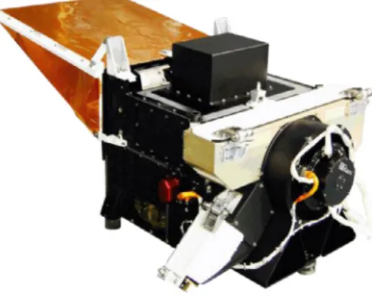
Fig. 1. The Glory APS.
from different viewing directions. The two instruments onboard ADEOS 1 and 2 are identical(Table 2), while the instrument on the PARASOL platform [22] was rotated by 90° to favor multidi-rectional viewing (a maximumof 16 directions compared to 14) overdailyglobalcoverage.Determinedbythealtitudeofthe corre-spondingorbits,thesizeoftheimagesvariesfrom2400× 1800km to1600× 2100km(across/alongtrack)withtherespectiveground resolutions of 7× 6 and5.3× 6.2km atnadir. The PARASOL plat-form is part of the A-Train and enables researchers to take ad-vantageofthepresence ofother instrumentsintheconstellation. The spectral coverage of the three instruments ranges fromblue (443nm) through nearIR (910nm)with three polarized spectral bands. For POLDER-3, the “bluest” polarized channel was moved from443 to490nm,anda 1020-nmchannel wasadded. Innova-tive techniques [86–88,101] have beendeveloped to calibratethe POLDERinstrumentsinflight.
2.1.2. APSonGLORY
TheAerosolPolarimetrySensor(Fig.1,[195]) waslaunchedon theGlorysatelliteon4March2011.ThisNASAmissionwouldyield comprehensive andhighly accurate data onthe chemical, micro-physical, and optical properties of aerosols andtheir spatial and temporaldistributions.Unfortunately,duetoamalfunctiononthe launchvehicle,theAPSdidnotreachitsintendedorbitandhence provided no data.Nonetheless, the developmentof the APS con-cept, relevant scientific analyses, and analyses of data from its airborne prototype (e.g., Ref. [44]) have strongly stimulated the progressofandinterestinpolarimetryasaremote-sensingtool.As a consequence,the conceptualdesign ofseveralrecent polarime-tersreliesontheAPSheritage.
The APS design yields a high polarimetric accuracy (0.2% or betterforDoLP),providesawiderangeandlargenumberof view-ingdirectionssampledforeachscene,anddenselycoversthe rele-vantVIS–SWIRspectral range.Theinstrumentusesa polarization-compensatedscanmirrorassemblytoscanalongthegroundtrack and thereby obtain the requisite range and number of viewing directions. Six boresighted refractive telescopes are paired, with eachpairmakingmeasurementsinthreespectralbands.One tele-scope ineach pairmakes simultaneousmeasurements ofthe lin-ear polarizationcomponentsoftheintensityinorthogonalplanes at0° and90° tothemeridionalplaneoftheinstrument,whilethe other telescope simultaneouslymeasures equivalentintensities in orthogonalplanesat45° and135°.Thisapproachensuresthatthe polarization signal isnot contaminatedby uncorrelatedspatialor temporalsceneintensityvariationsduringthecourseofthe polar-izationmeasurements,whichcouldcreatefalsepolarization.These measurements in eachinstantaneous field of view ina scan pro-vide thesimultaneous determinationofthe intensityandthe
de-Owing to its very fine angular resolution (250 angular views perscene), theAPSdesign providesthe uniquecapability to pro-fileneutralpolarizationpointsthatareverysensitivetotheheight andimaginary refractiveindex ofabsorbing aerosols [51],and to samplecloudbowsthat allowforthe retrievalofdropletsize dis-tributioninthetoplayerofcloudswithextremeprecision[32,34]. Furthermore,this type of fine angular resolution makes possible aerosolretrievalsovercloudsonthepixellevel.
2.1.3. MAIonTG-2
The Multi-Angle polarization Imager onboard the Tiangong-2 spacecraft waslaunched on 15 September 2016. The TG-2 is the secondChinesespacelaboratoryfollowingTG-1.Itsgoalisto ver-ifythetechnologyofspacerendezvousanddockingandalso con-duct aseriesofspaceexperiments.The MAIisan Earth observa-tion instrument providing multi-channel multi-angle polarization measurements. It has six channels, including three with polari-metricsensitivitycenteredat565,670, and865nm. Observations with12 differentviewingdirectionsforeachchannel ata resolu-tionof3kmcanbeobtained.Theinstrumentcaneffectivelydetect the informationon clouds (suchas cloud phase andtop height), aerosols, and atmospheric watercontent. Its capability for cloud phaseidentificationhasbeenconfirmedbytheMAIairborne sim-ulatorusedduringafieldcampaignon23October2015[100]. Dur-ingthiscampaign,a homogeneousstratocumuluscloud layerwas overflownatanaltitudeof3.7kmabovethesea.Threepolarization channelsoftheMAIaccuratelycapturethe characterofpolarized radiation of water clouds (primary cloudbow) near 140° scatter-ingangle.Additionally,duetothenon-solar synchronousorbitof theTG-2,polarization observationsunderdifferentgeometry con-ditions canbe obtained, whichcan provide aunique support for thedevelopmentofvectorradiativetransfermodels.
2.1.4. CAPIonTanSat
TheCloudandAerosol PolarizationImageronboardtheTanSat mission waslaunched on 22 December 2016 and is expected to operatefor three years. The 620-kg TanSat was sent into a sun-synchronous orbit about 700km above the earth and aims to monitorthe concentration, distribution,andflow of carbon diox-ide (CO2) in the atmosphere to help understand climate change
[242].TheCAPIisa5-channel(380,670,870, 1375,and1640nm) imager, with additional measurements of linear polarization at 670 and 1640nm. This instrument was designed to yield cloud andaerosolcharacteristics toimprovetheretrieval ofgreenhouse gases. The CAPI is a push broom systemimager using linear de-tectors, which consists of two units operating in the VIS and SWIRspectralranges.TheradiancemeasurementsfromtheUV to near IR with additional measurements of the Stokes parameters were designedfortheretrieval ofaerosoloptical and microphys-icalproperties.Thestrongersensitivityofpolarizedmeasurements toaerosolpropertiesprovides additionalindependentinformation
[48,49].
2.1.5. DPConGF-5
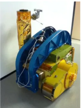
The Directional Polarimetric Camera onboard the GaoFen-5 spacecraft(Fig.2),whichisthefifthmemberoftheseriesofChina High-resolution Earth Observation System satellites of the CNSA, was launched on 9 May 2018. The GF-5 is also the flagship of theatmosphericenvironmentalmonitoringsatellitesamongCNSA on-orbitprograms. The DPC wasbuilt by the AIOFM of the CAS andconsistsofadigitalcamerawitha512× 512-pixelCCDmatrix. It has eight channels from 443 to 910nm, including three spec-tral bands (centeredat 490, 670, and 865nm) yielding polariza-tionmeasurements.Observationsforatleast9viewingdirections
488 O. Dubovik, Z. Li and M.I. Mishchenko et al. / Journal of Quantitative Spectroscopy & Radiative Transfer 224 (2019) 474–511
Fig. 2. DPC sensor onboard the GF-5 satellite.
atarget. TheDPCis designedforthe retrievalofspectral proper-tiesofatmosphericaerosol,includingthespectralAOT,theAE,and theFMF[140].Itcanalsoprovideatmosphericcorrection parame-tersfortheGreenhouse-gasesMonitoringInstrumentonboardthe samesatelliteGF-5.
2.2.Satelliteinstrumentswithmulti-angularand/orlimited polarimetriccapabilities
2.2.1. SGLIonGCOM–C
The Second Generation Global Imager onboard the Global ChangeObservationMission–Climatesatellite waslaunched on23 December2017andhasbeeninoperationsincethespringof2018. TheSGLI iscomposedoftwosensorsasthepush-broomVNIR ra-diometerandthewhisk-broominfrared scannerinstruments.The SGLImeasures theEarth’sreflectanceat19wavelengths fromthe nearUV (380nm)tofar IR(12µm). Thepolarization opticsis in-cludedintheVNIR,whichcanmeasureI,Q,andUassemi-Stokes parameters at 673.5 and 868.5nm. The polarization information is taken with three different directions of polarizers (−60°, 0°, and+60°). Note that the central polarizer (0°) is assigned to the forwarddirectionofthesatellite.TheVNIRpolarizationopticshas a tilting function that can measure+45° (forward ofnadir direc-tion) or−45° (backward)directional information;these large tilt-ing angles are equivalent to forward and backward edge of the POLDER-1and-2CCDsensors.Thetiltingdirectionischangedwith latitudeinorderto take themeasurements atside-scattering an-gles (∼90° to ∼120°), because the magnitude of linear polariza-tioninthe backwardscatteringregion islow.Accurately measur-ing small polarization features at large scattering angles is diffi-cultbecauseeachpositionofthethreepolarizersinthetelescope viewsslightlydifferenttargets.ThisimpliesthattheSGLImeasures syntheticI,Q,andUfortargetsbecauseofthe differentpositions ofthe linearCCD arraysin the focal plane ofthe telescope. Fur-thermore,the POLDER instruments also measure the synthetic I, Q, and U owing to the difference in acquisition times along the satellite track.Again,in theSGLI case, the angulardifference be-tweenthethree differentmeasurementswithapolarizer at−60°, 0°, and+60° is small. Each viewing angle of each polarizer is in-cludedin theSGLI level 1Bpolarization dataset.Also, such small polarizationisweakfromthesignal-to-noise-ratiopointofview.
Notethatthemeasurements ofI,Q,andUattwo wavelengths are only available from one viewing angle,compared to a max-imum of 14 directions from POLDER-1 and -2 or 16 directions
from POLDER/PARASOL. However, the non-polarized VNIR optics (i.e., most of observations from 380nm to 12µm) always takes nadir-looking measurements. This means that two-directional to-tal reflectances at wavelengths of 673.5 and 868.5nm are avail-able.TheIFOVsofthepolarizedandnon-polarizedVNIRopticsare 1000m(+45° or−45° direction)and250m,respectively.Although itcanbesaidthattheSGLIpolarizedVNIRsensorisasuccessorto POLDER,itwasnotdesignedformulti-angleobservations. 2.2.2. GOMEonERS-2,SCIAMACHYonEnvisat,andGOME-2on MetOp-A/B/C
TheGlobal OzoneMonitoringExperiment instrumentoperated onboard ESA’s ERS-2 satellite launched in July 1995. GOME was a smaller version of the Scanning Imaging Absorption Spectrom-eterforAtmospheric Chartographywhichwaslaunched inMarch 2003 onESA’s Envisatsatellite. Theseinstrumentswere designed to measure trace gases, especially ozone and related gases, by high-resolutionspectrometry:GOMEfrom240–790nmwitha0.2– 0.4nmresolution,andSCIAMACHYfrom240–2380nmwitha0.2– 1.5nm resolution. The instruments hada scan mirror which en-abledcross-trackscanninginnadir,aswellassidewaysviewingfor solarandlunarcalibration.Sincetheinstrumentsweresensitiveto thepolarization oftheincominglight, they carriedthree(GOME) orseven (SCIAMACHY) broad-band polarization sensors to detect the Stokes parameterQ. In thiswaythe incident signal could be correctedforpolarizationusingtheon-ground-calibrated polariza-tionsensitivityoftheinstrumentandthemeasuredQ[275]. SCIA-MACHYmeasurednotonlyinnadirbutalsoinlimbview[276].
An improved version of GOME is GOME-2 flown on the EU-METSAT’sMetOpsatellites.MetOp-A,MetOp-BandMetOp-Cwere launched in October 2006, September 2012 and November 2018, respectively. Like GOME, GOME-2 has 4096 spectral points from four main channelsper GOME-2 groundpixel. The footprint size is80× 40kmforthemain-channeldata.Theinstrumentalso mea-suresthestateoflinearpolarizationoftheEarth’sradianceintwo perpendiculardirections,usinglineardiodearrays,resultinginthe measurement ofthe spectral Stokes parameters Iand Q.The po-larization dataaredown-linkedin15 spectralbands coveringthe region from 312 to 800nm forboth polarization directions with a footprint of 10× 40km. Although the GOME, SCIAMACHY, and GOME-2dataare primarily aimedatgettinga detailedpictureof atmosphericchemistry,theyare alsoused fordetecting absorbing aerosols[9,95,236,268,277].
2.2.3. MISRonTerra
TheMulti-angleImagingSpectroRadiometer [65] waslaunched intoapolar,sun-synchronousorbitaboardNASA’sTerraspacecraft on18December1999.MISRusesninecamerastoimagetheEarth atninediscreteviewangles:0° (nadir)and26.1°,45.6°,60.0°,and 70.5° forwardandbackwardofnadir,providingglobalmappingof aerosolseverynine days.AlthoughMISRisnot apolarimeter(the cameras include Lyot depolarizers to render them insensitive to scene polarization),it underscores the importance ofmulti-angle observationsforaerosolremote sensingandprovides heritagefor developmentofits polarimetric successors,particularlyMAIA de-scribedinSection2.3.Multi-angleradianceobservationshelp sep-arateaerosolsignalsfromsurfacereflectionandprovidesensitivity toaerosolscatteringphasefunctions,whicharegovernedby parti-clesize,shape,andopticalcharacteristics[67,121,125,126].
2.3. Plannedsatelliteobservations 2.3.1. 3MIonEPS-SG
TheMulti-View Multi-ChannelMulti-PolarizationImaging mis-sion [89,156] planned to fly on the EUMETSAT Polar System – Second Generation platform in the time-frame 2020–2040, is a
O. Dubovik, Z. Li and M.I. Mishchenko et al. / Journal of Quantitative Spectroscopy & Radiative Transfer 224 (2019) 474–511 489
Fig. 3. The 3MI concept of multi-view, multi-spectral, and multi-polarization sampling.
2D wide field ofview radiometerdedicated toaerosol andcloud characterizationforclimatemonitoringandatmospheric composi-tion studies,aswell asforairquality applicationsandnumerical weatherprediction.Theinstrumentalconceptofthe3MIislargely inherited from POLDER-3. The purpose of the 3MI is to provide multi-spectral(from410 to2130nm),multi-polarization(–60°,0°, and+60°),andmulti-angular(10 to 14views)imagesof the out-goingtop-of-atmosphereradiation.The3MIinformationonaerosol and cloud properties(and that relevant toaerosol–cloud interac-tion studies)is expectedtofarexceedthat fromthestandard ra-diometers (e.g., MODIS) performing intensity-only measurements at a single viewing angle. The clear shortcoming of the 3MI is theabsenceofthermalinfraredchannels.However,these measure-ments will be available from the METimage and IASI-NG instru-mentsplannedtoflyonthesamesatelliteplatformallowinga syn-ergetic cloud retrieval algorithm to be developed. The Sentinel-5 high-resolutionspectrometerwillprovideinformationfromtheUV totheSWIR,througha coarserhorizontalsampling. These instru-ments will provide useful crosscalibration (radiometric, spectral, andgeometrical)withthe 3MI.Indeed,the3MI hasno on-board calibration andthusdependson vicarioustechniquesusing Earth reference scenes as calibration targets. From the POLDER-3 her-itage[88,101,156],severalmethodsareavailabletobeadaptedand used forthe 3MI vicariouscalibration duringcommissioning and operationalphases:Rayleighscattering,sunglint,desertsites,deep convective clouds[87,88],Moonviews, andcrosscalibration with otherinstruments.Thesemethodsarecomplementaryandbuilda strong toolbox forcalibrationandvalidation. Thisset ofmethods willalsocovervicariouscalibrationofthenew3MISWIRchannels. Themethodsarestillunderimprovement(e.g.,overAntarcticaand usingMoonviews[86]).However,theperformanceofthese meth-ods hasalreadyshownthat therequisite calibrationaccuracycan beachieved.
The 3MI heritage comes from the POLDER/PARASOL missions which are based on a mature technology, with proven reliability fundamentalforEUMETSAToperationalproductpolicy.The3MIis anewEUMETSATmissionandhasthereforenolinktoEPS-SG in-struments. The3MIdesign consistsbasicallyofa filteranda po-larizer wheel rotating in front of the detectors (Fig. 3). For de-signpurposes,thespectralchannelsaresplitintoVNIRandSWIR filters andpolarizers withdedicated detectors andoptical heads. The spectralchannelsarelisted inTable3.Themulti-polarization (three acquisitions within 1s for the polarized channels) and multi-spectralacquisitionsaredonewithinawheelrotationperiod oflessthan5.5s.Themulti-viewingcapabilityisachievedby suc-cessive imagesof the samespectral channel observingthe scene fromdifferentangles,allowingupto14viewspertarget.
The 3MI products (Table 3) will provide valuable information
Fig. 4. Computer rendering of the MAIA instrument. The camera field of view is pointable in two axes using a gimbal assembly. Dimensions of the instrument are approximately 0.9 m (W) × 0.7 m (L) × 0.5 m (H).
radiativeforcingoftheEarth’satmosphere. The3MIproducts will aswellbebeneficialtotheNWPbyimprovingsoundingand imag-ingdatafromMETimage,Sentinel-5,andtheIASI-NGwithabetter constraintontheartefacts induced byscatteringandpolarization ofradiationby aerosolsandtheidentification ofcirrusclouds.In general,the3MIproductswillbeusedtoimproveairquality mon-itoring applications (e.g., aerosol mass load for particles smaller than2.5µm(PM2.5)or10µm(PM10)).Combinedwiththeaerosols’
absorptionindex, naturalhazardslikevolcanicashorfire plumes canalsobeobserved,thereby contributingtonow-castingforash andfiredetection.
2.3.2. MAIA
NASAselected theMulti-Angle ImagerforAerosols (Fig.4) in-vestigationin 2016 as part of its Earth Venture Instrument pro-gram.AttheheartoftheMAIAinstrumentisaspectropolarimetric camera makinguse ofthe same polarimetricretardance modula-tiontechnique employed inAirMSPI andAirMSPI-2 (Section 2.4). However, unlike its airborne counterparts in which the camera is mounted on a single-axis gimbal, the MAIA camera will be mountedon a dual-axisgimbal,enabling bothalong-track multi-angle viewing over a±70° range (at the Earth’s surface) as well as observations of targets displaced in the cross-track direction from the subsatellite ground track. MAIA is to be launched into alow-Earth,sun-synchronous,polarorbit. Thebaseline orbit