HAL Id: hal-01109557
https://hal.sorbonne-universite.fr/hal-01109557
Submitted on 26 Jan 2015
HAL is a multi-disciplinary open access
archive for the deposit and dissemination of
sci-entific research documents, whether they are
pub-lished or not. The documents may come from
teaching and research institutions in France or
abroad, or from public or private research centers.
L’archive ouverte pluridisciplinaire HAL, est
destinée au dépôt et à la diffusion de documents
scientifiques de niveau recherche, publiés ou non,
émanant des établissements d’enseignement et de
recherche français ou étrangers, des laboratoires
publics ou privés.
status and future developments
Jean-Pierre Gattuso, W Kirkwood, J.P Barry, E Cox, F Gazeau, L Hansson, I
Hendriks, D.I. Kline, P Mahacek, Sophie Martin, et al.
To cite this version:
Jean-Pierre Gattuso, W Kirkwood, J.P Barry, E Cox, F Gazeau, et al.. Free-ocean CO 2 enrichment
(FOCE) systems: present status and future developments. Biogeosciences, European Geosciences
Union, 2014, 11 (15), pp.4057-4075. �10.5194/bg-11-4057-2014�. �hal-01109557�
www.biogeosciences.net/11/4057/2014/ doi:10.5194/bg-11-4057-2014
© Author(s) 2014. CC Attribution 3.0 License.
Free-ocean CO
2
enrichment (FOCE) systems: present status and
future developments
J.-P. Gattuso1,2, W. Kirkwood3, J. P. Barry3, E. Cox1,2, F. Gazeau1,2, L. Hansson4, I. Hendriks5, D.I. Kline6, P. Mahacek1,2, S. Martin7,8, P. McElhany9, E. T. Peltzer3, J. Reeve10, D. Roberts11, V. Saderne12, K. Tait13, S. Widdicombe13, and P. G. Brewer3
1Sorbonne Universités, UPMC Univ Paris 06, Observatoire Océanologique, 06230 Villefranche-sur-mer, France 2CNRS-INSU, Laboratoire d’Océanographie de Villefranche, 06230 Villefranche-sur-mer, France
3Monterey Bay Aquarium Research Institute, 7700 Sandholdt Road, Moss Landing, CA 95039, USA
4Ocean Acidification International Coordination Centre, IAEA-Environment Laboratories, 4a Quai Antoine 1er, 98000
Monaco, Principality of Monaco
5Global Change department, IMEDEA (CSIC-UIB), Instituto Mediterráneo de Estudios Avanzados, C/ Miquel Marqués 21,
07190 Esporles (Mallorca), Spain
6Scripps Institution of Oceanography, Integrative Oceanography Division, University of California, San Diego, 9500 Gilman
Drive, MC 0218, La Jolla, CA 92093–0218, USA
7Sorbonne Universités, UPMC Univ Paris 06, Station Biologique, Place Georges Teissier, 29688 Roscoff Cedex, France 8CNRS, Station Biologique, Place Georges Teissier, 29688 Roscoff Cedex, France
9Conservation Biology Division, Northwest Fisheries Science Center, National Marine Fisheries Service, National Oceanic
and Atmospheric Administration, 2725 Montlake Blvd. E, Seattle, WA 98112, USA
10Department of the Environment, Channel Highway, Kingston, Tasmania, Australia
11Antarctic Climate and Ecosystems Cooperative Research Centre, University of Tasmania, Private Bag 80, Hobart T 7001,
Australia
12Benthic Ecology group, GEOMAR – Helmholtz Centre for Ocean Research in Kiel, Kiel, Schleswig-Holstein, Germany 13Plymouth Marine Laboratory, Prospect Place, West Hoe, Plymouth PL1 3DH, UK
Correspondence to: J.-P. Gattuso ([email protected])
Received: 20 February 2014 – Published in Biogeosciences Discuss.: 11 March 2014 Revised: 23 June 2014 – Accepted: 25 June 2014 – Published: 1 August 2014
Abstract. Free-ocean CO2enrichment (FOCE) systems are
designed to assess the impact of ocean acidification on bi-ological communities in situ for extended periods of time (weeks to months). They overcome some of the drawbacks of laboratory experiments and field observations by enabling (1) precise control of CO2enrichment by monitoring pH as
an offset of ambient pH, (2) consideration of indirect ef-fects such as those mediated through interspecific relation-ships and food webs, and (3) relatively long experiments with intact communities. Bringing perturbation experiments from the laboratory to the field is, however, extremely challeng-ing. The main goal of this paper is to provide guidelines on the general design, engineering, and sensor options required to conduct FOCE experiments. Another goal is to introduce
xFOCE, a community-led initiative to promote awareness, provide resources for in situ perturbation experiments, and build a user community. Present and existing FOCE sys-tems are briefly described and examples of data collected presented. Future developments are also addressed as it is anticipated that the next generation of FOCE systems will include, in addition to pH, options for oxygen and/or temper-ature control. FOCE systems should become an important experimental approach for projecting the future response of marine ecosystems to environmental change.
1 Introduction
The oceans absorb about 25 % of anthropogenic carbon diox-ide (CO2) emissions, moderating the rate and severity of
cli-mate change (Le Quéré et al., 2013). While this is a valu-able service to human societies, it has important implications for the oceans. The massive input of CO2generates critical
changes in the chemistry of seawater, especially in the car-bonate system. These changes are collectively referred to as “ocean acidification” because increasing CO2lowers
seawa-ter pH (i.e., increases its acidity). The pH of ocean surface water has decreased by about 0.1 units since the beginning of the industrial era, corresponding to a 26 % increase in hy-drogen ion concentration (Orr, 2011). Earth system models project a global additional decrease in pH by 2100 ranging from 0.06 to 0.32 units depending on our future emissions, with the latter value, associated with a 163 % increase in hy-drogen ion concentration from preindustrial times, being the best estimate based on our emissions trajectory (Ciais et al., 2013).
Ocean acidification may have profound impacts on ma-rine biota, for example through the direct effects of pH on intercellular transport mechanisms that control the physiol-ogy and metabolism of marine organisms and the decreased availability of carbonate ions, used by many species to build calcareous shells and skeletons (Kroeker et al., 2013). Other functional groups, such as primary producers that use CO2to
produce organic matter, may take advantage of its increased availability in the coming decades (Riebesell and Tortell, 2011).
As studies of the consequences of ocean acidification for marine organisms and ecosystems expanded rapidly over the past decade, the methods employed to evaluate the effects of future changes in ocean chemistry have become more sophis-ticated. Initial studies frequently involved measurements of the survival or physiological response of individuals of ma-rine species to large changes in the partial pressure of CO2
(pCO2) or pH while held in small containers under
labora-tory conditions with modified seawater, microbes, and food conditions (Gattuso and Hansson, 2011). This approach in-creased the level of understanding of the effects of these en-vironmental changes on individual species but provided little information concerning the response of natural assemblages where indirect effects can be important. Indirect effects oc-cur where species that are not directly affected by changing ocean chemistry nonetheless experience changes in abun-dance or distribution because their prey, predators, or com-petitors are reduced or increased by ocean acidification. An-other example of indirect effects is possible on the substra-tum, such as dissolution of the calcium carbonate framework. In order to improve our understanding of the future im-pacts of ocean acidification on marine life, three major types of in situ data can be used: (1) time series of changes in com-munity structure correlated with changes in carbon chem-istry (2) observational studies that compare patterns or
pro-cesses between areas that differ naturally in seawater acid-ity, and (3) perturbation experiments, where environmen-tal conditions are manipulated to compare patterns or pro-cesses between artificially acidified and control conditions (Barry et al., 2010). Although time series directly document-ing changes in organismal abundance or distribution in re-sponse to ocean acidification are extremely valuable, long-term data sets coupling biological observations and carbon chemistry measurements are generally not available (but see, for example, Wootton et al., 2008). In addition, using time se-ries analysis, it is difficult to disentangle any ocean acidifica-tion effects from the effects of other environmental changes, such as climate, pollution, or fishing. Comparing contem-porary areas with different carbonate chemistry conditions, such as near natural CO2vents (Fabricius et al., 2011;
Hall-Spencer et al., 2008; Martin et al., 2008) or along other gra-dients (e.g., Thresher et al., 2011), can provide critical data and an insight into the long-term impacts of ocean acidifi-cation on benthic organisms, communities, and ecosystems (Hall-Spencer et al., 2008; Martin et al., 2008; Wootton et al., 2008; Fabricius et al., 2011). However, spatial comparisons have several limitations: there is no control over treatment conditions and (in the case of vent studies) organisms are lo-cally exposed to short-term extreme pH levels, and there are confounding factors, such as the release of potentially harm-ful gases (Boatta et al., 2013) and immigration into the study site of juveniles from outside the study areas, which often make the results difficult to interpret.
The free-ocean CO2enrichment (FOCE) experimental
ap-proach attempts to address some of the limitations of other methods by conducting ocean acidification experiments in situ. FOCE experiments are analogous to pelagic mesocosm (Riebesell et al., 2013a) experiments that examine the re-sponse of natural plankton communities to controlled pH perturbations, advancing methods of ocean acidification re-search toward more comprehensive studies of whole com-munities and embedded processes under mostly natural con-ditions (e.g., Riebesell et al., 2013b). Free-air CO2
enrich-ment (FACE) experienrich-ments in terrestrial systems, which have been providing critical and unexpected data on the impacts of elevated CO2on terrestrial ecosystems for more than two
decades, have led to over 120 peer-reviewed publications (Ainsworth and Long, 2005). The first FOCE systems were developed at the Monterey Bay Aquarium Research Insti-tute (MBARI; Walz et al., 2008; Kirkwood et al., 2011), but other FOCE systems have since been deployed or are being planned around the globe (see Sect. 4).
We define FOCE as a technology facilitating studies of the consequences of ocean acidification for marine organ-isms and communities by enabling the precise control of CO2 enrichment within in situ, partially open,
experimen-tal enclosures. By focusing, for reasons described below, on systems that use partially open enclosures, this definition does not include all marine in situ carbonate parameter ma-nipulation experiments. In pelagic mesocosm experiments
(Riebesell et al., 2013a), a bag completely encloses a vol-ume of seawater. The carbonate system is generally altered at the beginning of the experiment through additions of CO2
-enriched seawater, and subsequently drifts in response to bi-ological processes and air–sea gas transfer. A fully enclosed benthic in situ CO2enrichment system has also been
devel-oped. The Submersible Habitat for Analyzing Reef Quality (SHARQ) system has been modified from strictly measuring carbonate parameters (Yates and Halley, 2006) to manipu-lating carbonate parameters by the addition of CO2enriched
seawater (K. Yates, personal communication, 2013). CO2 bubbling in open water without any enclosure has
also been used (Arnold et al., 2012). This experiment is more “free ocean” than is encompassed in our FOCE definition, which is restricted to partially enclosed systems. Because the chemical reactions that occur when CO2is added to seawater
are relatively slow (on the order of tens of seconds to minutes depending on temperature and pH), the open water approach does not enable precise control of carbonate system param-eters by pH monitoring because it does not allow sufficient time to ensure full equilibration of added CO2in seawater.
Since there are no experimental enclosures to regulate water flow, the method generates highly variable pH under variable current speed or direction. This approach is therefore more similar to natural CO2vents than to FOCE systems and has
the associated advantages and disadvantages.
Although straightforward in concept, engineering and lo-gistical aspects of FOCE technology are very challenging to implement. The goal of this paper is to provide informa-tion on the general design of FOCE experiments (Sect. 2) as well as recommended sensors, suggested designs depending on scientific needs, and details about the pH control system (Sect. 3). It also provides an overview of past and present FOCE systems (Sect. 4), outlines future engineering and re-search directions (Sect. 5), and describes community build-ing and overarchbuild-ing activities (Sects. 6 and 7).
2 General design
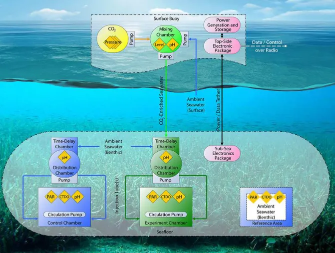
The key elements of any FOCE experimental units are par-tially open enclosures that allow for control of seawater con-ditions but retain through-flow of ambient seawater, a CO2
mixing system, sensors to monitor ambient and enclosure pH as well as other critical environmental parameters, and a control loop to regulate the addition of gases or liquids to each experimental enclosure (Fig. 1). Ideally, FOCE systems could control the carbonate chemistry and other parameters (e.g., oxygen, temperature) in several relatively large experi-mental plots (ca. > 10 m2) and would be fully open (i.e., not requiring enclosures). In practice, FOCE systems require far more constrained conditions.
Another key element of FOCE systems is the flexibility in the design to enable investigation of different communities and environments (see Sect. 4). The environmental and
lo-gistical features of potential experiment sites introduce chal-lenges to configuring a FOCE experiment. The availability of electrical power, sources and delivery of CO2,
experi-ment enclosure size, and regional seafloor topography and flow patterns are the primary factors that determine the final implementation. Furthermore, the expected duration of the FOCE system and planned experiments as well as the size and the availability of the team available for maintenance and data collection are important considerations for logistics and associated costs.
It is necessary to measure various parameters in the area inside and outside the controlled volume. In existing FOCE systems, pH data are needed as the perturbed pH is usually determined by an offset to the ambient pH. Also, one of the most important concerns for FOCE experiments is being able to ensure that natural conditions, except for pH, prevail in the experimental enclosures despite the partial confinement. For that purpose, measurements of salinity, temperature, oxygen, and a second parameter of the carbonate system outside the controlled volume are desirable. The deployment of FOCE systems in areas where local physicochemical and biological conditions have been monitored for several years is recom-mended in order to place the experimental conditions in a broader timescale.
2.1 Enclosures
The land-based free-air CO2 enrichment (FACE)
experi-ments involved horizontal or vertical pipes placed in a circle around areas of forest, grassland, or commercial crops us-ing natural and fully open conditions (Ainsworth and Long, 2005). Although it is desirable for FOCE experiments to mimic FACE and be as open as possible to maintain a natural environment, there are a number of practical issues that pre-vent the use of a fully open experiment, the most important being the slow reaction kinetics of CO2chemistry in
seawa-ter (see Sect. 2.4). The design of the enclosure can vary con-siderably depending on the focus of experiments, but must allow some ventilation of the enclosed plot with ambient wa-ter. Some designs may allow the flow of detritus through the enclosure, while others may be fully closable and function temporarily as respirometric chambers. Enclosures may be fabricated from various materials. Acrylic may be most ap-propriate for shallow-water experimental studies that require natural light. Although acrylic is difficult to work with, and has less intrinsic strength, it has superior optical properties than polycarbonate, and transmits the full spectrum of nat-ural light. In addition, acrylic does not lose these properties with age, while polycarbonate exposed to sunlight slowly be-comes opaque.
The behavior of animals may also influence the design and openness of FOCE experiments. Experimental enclo-sures may contain mobile animals which can either swim or burrow out of the enclosure if or when conditions become ad-verse. The structure of the FOCE enclosure itself can attract
Figure 1. Conceptual diagram of a FOCE system. The number of control, experiment, and reference areas vary depending on the experimental
design and budget. Additional sensors are also optional. PAR: photosynthetically active radiation; CTDO: conductivity, temperature, salinity, and oxygen sensors. See the main text for definitions of the subcomponents.
animals searching for shelter, which may in turn affect the hydrodynamic regime and result in an increase in deposition of nutrient-rich fecal material. The enclosure may also con-tain prey for predators able to burrow under the walls into the enclosure. It may, therefore, be desirable to limit both ac-cess and egress to the enclosure (e.g Deep FOCE, hereafter dpFOCE; Sect. 4.1). Alternatively, if the FOCE enclosure is large enough, additional cages or baskets may be placed inside it to safely contain experimental plants or animals. Care must be taken not to anchor the enclosure too deeply into non-cohesive sediment, as this may disrupt the pore-water flow and the advective exchange of material across the sediment–water interface.
2.2 Size and volume
The area and volume of existing and planned FOCE units range from 0.25 to 2 m2 and 0.06 to 2 m3 (Table 1). Units should be as large as possible, as large units enable smoothing-out of small-scale changes in the composition of the community and better represent the response of the
com-munity. However, there are critical engineering and financial constraints on the size of FOCE units related to the amount of CO2required, the number of replicate enclosures required,
the performance of the CO2control system, and the
signal-to-noise ratio. Small FOCE units can be used to investigate the response of specific representatives of the ecosystem, for example sedimentary areas within a coral reef or seagrass bed.
Although it would reduce some of the size constraints, ma-nipulating the carbonate system in lagoons or embayment has never been attempted, and the large amount of CO2 which
would need to be added seems to preclude such experiments. It may be possible, however, to perform FACE-like experi-ments in sectors of very shallow areas subject to a unidirec-tional water flow, such as coral reef flats. Controlling pH up-stream would subject the downup-stream community to future conditions, although with less ability to control the future pH conditions.
The present and planned FOCE systems have very differ-ent designs (see Sect. 4) because they focus on differdiffer-ent bio-logical communities, explore different engineering options,
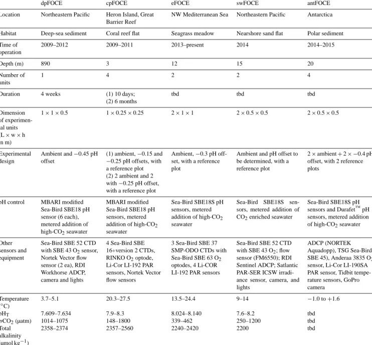
Table 1. Design of past, current, and planned FOCE systems. tbd: to be determined.
dpFOCE cpFOCE eFOCE swFOCE antFOCE Location Northeastern Pacific Heron Island, Great
Barrier Reef
NW Mediterranean Sea Northeastern Pacific Antarctica Habitat Deep-sea sediment Coral reef flat Seagrass meadow Nearshore sand flat Polar sediment Time of operation 2009–2012 2009–2011 2013–present 2014 2014–2015 Depth (m) 890 3 12 15 20 Number of units 1 4 2 2 4
Duration 4 weeks (1) 10 days; (2) 6 months tbd tbd tbd Dimension of experimen-tal units (L × w × h in m) 1 × 1 × 0.5 1 × 0.25 × 0.25 2 × 1 × 1 2 × 0.5 × 0.5 2 × 0.5 × 0.5 Experimental design Ambient and −0.45 pH offset (1) ambient, −0.15 and −0.25 pH offsets, with a reference plot (2) 2 ambient and 2 with −0.25 pH offset, with a reference plot
Ambient, −0.3 pH off-set, with a reference plot
Ambient and pH offset to be determined, with a reference plot
2 × ambient + 2 × −0.4 pH offset, with 2 reference plots
pH control MBARI modified Sea-Bird SBE18 pH sensor (6 each), metered addition of high-CO2seawater MBARI modified Sea-Bird SBE18 pH sensors, metered addition of high-CO2 seawater Sea-Bird SBE18S pH sensors, metered addition of high-CO2 seawater
Sea-Bird SBE18S sen-sors, metered addition of CO2enriched seawater
Sea-Bird SBE18S pH sensors and Durafet™pH sensors, metered addition of high-CO2seawater
Other sensors and equipment
Sea-Bird SBE 52 CTD with SBE 43 O2sensor,
Nortek Vector flow sensor (2 ea), RDI Workhorse ADCP, camera and lights
4 Sea-Bird SBE 16+version 2 CTDs, RINKO O2optode,
Li-Cor LI-192 PAR sensors, Nortek Vector flow sensors
3 Sea-Bird SBE 37 SMP-ODO CTDs with Sea-Bird SBE 63 O2
optodes, 4 Li-COR LI-192 PAR sensors
Sea-Bird SBE 52 CTD with SBE 43 O2; flow
sensor (FM6550); RDI Sentinel ADCP; Satlantic PAR-SER ICSW irradi-ance sensor, camera, and lights
ADCP (NORTEK Aquadopp), TSG Sea-Bird SBE 45), Anderaa 3835 O2
sensor, Li-Cor LI-190SA PAR sensor, Tidbit tempe-rature sensors, GoPro camera Temperature (◦C) 3.7–5.1 20.3–27.5 13.5–24.4 9–14 −1.0 to +1.6 pHT 7.609–7.634 7.9–8.3 8.024–8.140 7.6–8.2 tbd pCO2(µatm) 1014–1075 148–1800 339–462 250–1200 tbd Total alkalinity (µmol kg−1) 2358–2374 2357–2560 2240–2420 2200 tbd
and were subject to different logistical constraints. There would be considerable benefits in using more standardized systems: it would ensure comparability of results, the devel-opment of joint experiments with an increased number of en-vironmental conditions, or increased replication. The size of complete FOCE systems would benefit from modularity that eases the complexity of shipment and assembly. FOCE in-stallations in extreme environments may be logistically chal-lenging and will benefit from careful planning, as well as pre-assembly of surface and underwater modules.
2.3 Number of subunits and experimental design The design of each FOCE experiment uniquely reflects the goals and the approach taken by the investigators for the en-vironment and biological community studied. Possible ex-perimental designs fall into three broad categories (Table 2). The very first FOCE system constructed (dpFOCE) had only one unit with a manipulated carbonate chemistry. This was primarily an engineering test unit to learn about controlling CO2enrichment by monitoring the internal pH offset versus
ambient seawater. Later designs used at least two units, one serving as a control and one or two having their carbonate system manipulated.
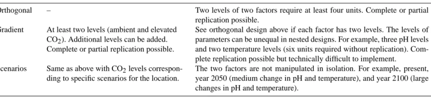
Table 2. Possible experimental designs of FOCE experiments.
Single factor Two factors
Orthogonal – Two levels of two factors require at least four units. Complete or partial replication possible.
Gradient At least two levels (ambient and elevated CO2). Additional levels can be added.
Complete or partial replication possible.
See orthogonal design above if each factor has two levels. The levels of parameters can be unequal in nested designs. For example, three pH levels and two temperature levels (six units required without replication). Com-plete replication possible but technically difficult to implement.
Scenarios Same as above with CO2levels
correspon-ding to specific scenarios for the location.
The two factors are not manipulated in isolation. For example, present, year 2050 (medium change in pH and temperature), and year 2100 (large changes in pH and temperature).
Design should also include randomization, replication, and controls (Hurlbert, 1984; Tilman, 1989). Economic con-straints are likely to limit the number of enclosures, but there should be several, if possible, in order to analyze the data through regression (requiring multiple enclosures with in-creasing levels of treatment) rather than through analyses of variance (see Havenhand et al., 2010).
Because of cost and feasibility, replication is challeng-ing for FOCE experiments, particularly for studies that re-quire (1) large units, (2) deployment in a challenging en-vironment, or (3) lengthy testing durations. A struggle be-tween the need to replicate and the need to study pro-cesses at appropriately large natural scales has existed for decades (Carpenter, 1990). Adding to design difficulty, repli-cates collected from within the same mesocosm are consid-ered as pseudo-replicates (Hurlbert, 1984; Gamble, 1990; Heffner et al., 1996). Environmental impact studies have dealt with the “pseudo-replication problem” by sampling through time (Stewart-Oaten et al., 1986; Underwood, 1994; Stewart-Oaten and Bence, 2001). When necessary, FOCE ex-periments could benefit from a similar, replication-in-time approach. Repeating long-term experiments can be difficult or impossible, depending on funding. In addition, it is very likely that the FOCE enclosures must be relocated between repeated experiments to increase independence between ex-perimental replicates (in time). Hence, if at all possible, mul-tiple enclosures should be preferred.
To date, nested or fully crossed designs to test the impacts of multiple stressors with FOCE have not been performed. However, FOCE systems could be deployed along natural or man-made environmental gradients and used with regression analyses to examine multistressor impacts (see Sect. 5 for further discussion). Alternately, researchers could use sce-nario or orthogonal approaches.
Because of the variability in organismal and community processes, differences among treatments need to be large to be detected. Despite replication limitations, Kline et al. (2012) were able to detect consistent differences in the dis-solution of calcified structures. The authors also argued that FOCE experiments have inherent value that laboratory exper-iments do not. Oksanen (2001) made an eloquent argument
that an experiment conducted at the ecosystem level with limited replication, if scientifically grounded, arguably pro-vides a more useful understanding than many well-replicated laboratory investigations. Similarly, Heffner et al. (1996) pointed out that even Hurlbert (1984), in his article on eco-logical field experiments, recognized that the quality of an experiment depends upon more than design. Furthermore, a meta-analysis, which resembles a nested design with repli-cates, could be conducted with FOCE experiments to identify any unusual experimental outcomes. A “control” enclosure allowed to fluctuate at natural pH levels is necessary in FOCE designs to account for the artificial boundary created by the structure which is absent in nature. Inside the structures, ev-ery effort should be taken to mimic natural conditions. Fur-thermore, the “perturbed” and “treated” environment and or-ganisms should be manipulated in a similar manner. For ex-ample, the pumping system used to deliver CO2into treated
structures should ideally be used in the control enclosure (without CO2addition). Also, FOCE experiments conducted
over several months will need to account for seasonality. In these instances, a natural/ambient or reference area, outside the enclosure and open to the environment, should be consid-ered in the experimental design.
Once the experimental design has been defined according to the budget available as well as technical and logistical con-straints, the pH or pCO2levels need to be determined. Barry
et al. (2010) provide comprehensive guidance for selecting these levels. Unless the goal of the experiment is to iden-tify physiological and molecular pathways, in which case extreme pH values can be useful, FOCE experiments gener-ally use environmentgener-ally relevant carbonate chemistries. The approach usually consists of lowering pH in the perturbed units by a fixed offset value corresponding to a pH value projected according to a CO2emission scenario (for
exam-ple, one of the representative concentration pathways; van Vuuren et al., 2011). In contrast to many laboratory experi-ments which used a constant carbonate chemistry, the FOCE technology is one of the approaches that maintains the nat-ural daily and seasonal pH changes. It is worth noting that, to date, no FOCE experiment has attempted a treatment to increase pH to mimic preindustrial (+0.1 units) or glacial
(+0.2 units) pH, partially due to the chemical difficulty of removing CO2from seawater.
2.4 pH manipulation
Initial trial experiments using a fully open system have high-lighted the difficulties in creating accurate low-pH conditions in a freely moving body of seawater (Walz et al., 2008). Sub-sequently, all chemical equilibrium FOCE experiments have been semi-enclosed and made use of the Zeebe and Wolf-Gladrow (2001) CO2kinetic model of e-folding time (τ ) to
calculate the time delay between CO2 addition and
equili-bration for a given pH, CO2concentration, and temperature.
Because the chemical reactions between the various carbon-ate species are slow, one needs to allow sufficient time for equilibrium to be reached before the introduction of the CO2
enriched seawater into the experimental chamber. For FOCE experiments, equilibrium is assumed to have been reached at any time past 3×τ . By using these calculations and continued monitoring of pH, temperature, and current velocity, a set pH can be successfully maintained even in areas of low temper-ature, such as dpFOCE and Antarctic FOCE (antFOCE), and high flow rates and high wave energy, such as Coral Proto FOCE (cpFOCE) and European FOCE (eFOCE).
Early FOCE prototypes developed at MBARI used hy-drochloric acid or liquid CO2for the early proof-of-concept
experiments. It would also be possible to inject CO2or CO2
-rich air as this requires special handling and delivering gases is more difficult than delivering water. It also introduces the added difficulty of equilibrating seawater with a gas which is considerably slower than mixing two water bodies. Conse-quently, all recent FOCE systems have used metered addition of CO2-enriched, low-pH seawater in the enclosures, which
is one of the recommended approaches of pH manipulation because it closely mimics the natural process of ocean acidi-fication (Gattuso et al., 2010). The delivery of CO2-rich
sea-water, obtained by bubbling pure CO2through seawater, is
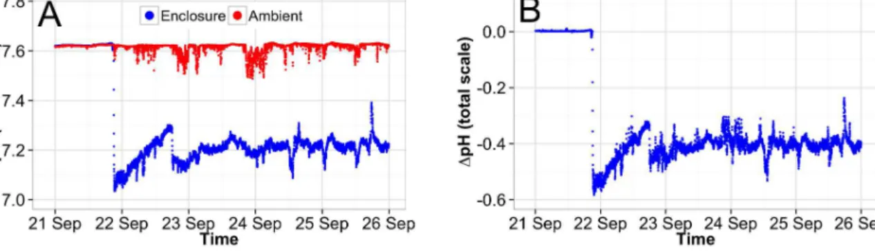
continually adjusted to maintain a constant pH offset relative to ambient pH, or to maintain a constant pH level in experi-mental enclosures. An example of a pH regulation test in the frame of the dpFOCE project (Fig. 2) demonstrates that pre-cise pH control can be achieved. The negative spikes in am-bient seawater trace are due to “blowback” of CO2-treated
seawater onto the external sensors. This illustrates the need for bidirectional flume operation (so that the outlet is always downstream of the external sensor) or locating the external sensors further away from the test chamber.
The key elements of any pH manipulation system include the CO2mixing system, sensors to continuously monitor
am-bient and enclosure pH, and a control loop to regulate the flow of CO2-enriched seawater (ESW) to each enclosure.
The best option is to set up a supply reservoir that allows for variable delivery on demand. The manufacture of ESW and pH control can be performed from a shore station, buoy,
or nearby apparatus, with a hose delivering the ESW to the enclosures.
In general, the rate and range of pH change in experimen-tal enclosures should be aligned with the pattern of natu-ral pH variation at the study site, which likely reflects the physiological tolerances, resilience, and potential for adap-tation to pH changes by the local biological assemblage. The natural range and variability of pH conditions experi-enced by the organisms may effectively have profound con-sequences on their physiology (e.g., Price et al., 2012). Many nearshore environments are exposed to large diurnal fluctu-ations in pH associated with daytime and nighttime changes in the intensity of photosynthesis/respiration and/or calcifica-tion/dissolution, as well as water advection owing to tidal cy-cles and changes in winds (Andersson and Mackenzie, 2012). Note, however, that alternative treatments such as constant pH or abrupt changes may be required for particular experi-mental questions.
Hofmann et al. (2011) reported rates of change in pH for various ecosystems. Among them, upwelling regions, estu-aries, coral reefs, and kelp forests exhibit large daily fluctu-ations of about 0.25 units, corresponding to mean rates of pH changes of 0.01–0.04 units h−1. Diel range similar to or larger than the changes projected over the next century are often measured in coral reefs (e.g., Price et al., 2012) and tropical estuaries (Yates et al., 2007). In contrast, changes in pH in the open ocean do not exceed 0.001 units h−1 (Hof-mann et al., 2011). In temperate systems, shallow-water habi-tats dominated with macrophytes are also likely to present strong diurnal pH variations, with the highest variability in the shallowest waters and decreasing with increasing water depth (Middelboe and Hansen, 2007). Diel pH fluctuation in macroalgal-dominated communities may reach 1 units h−1
(varying from pH 7.8 to 8.6, presumably on the US National Bureau of Standards (NBS) scale; Middelboe and Hansen, 2007). Even larger changes may occur in the tidal zone. For example tidal pools experienced pH oscillations related to the tide with rapid changes of pH as high as 1 to 3 units in low-level rock pools in Brittany (pHTfrom 7.7 to 8.6; Egilsdottir
et al., 2013) and high-level rock pools in Scotland (pH from 6.4 to 9.4, presumably on the NBS scale; Morris and Taylor, 1983). Organisms exposed to such conditions may experi-ence rapid pH changes as high as 0.1 to 0.3 pH units h−1in the surrounding seawater. However, only the pH of seawater surrounding the organism affects its physiology. The pH at the surface of the organism (diffusion boundary layer) may differ from the mainstream seawater due to exchanges related to metabolic activities, which may locally modify the pH mi-croenvironment (Hurd et al., 2011). The seawater flow at the surface of the organism is also important as it sets the thick-ness of the layer. For example, over a diel cycle, coralline algae encounters pH changes of +0.5 units in the light and
−0.35 units in the dark relative to the pH of ambient seawa-ter (Hurd et al., 2011). Sea urchins may also be subjected to very low pH values (down to 7.5 on the NBS pH scale) at
Figure 2. pH regulation test performed in the frame of the dpFOCE project, targeting a pH offset of −0.4 units.
their surface in slow flows. Conversely, under high flows, pH at the surface of the organisms is close to ambient pH. The surrounding hydrodynamic environment as well as the organ-isms’ physiology and morphology should thus be considered for evaluating the differential susceptibility of organisms to pH changes.
The rate of pH decrease to reach the experimental off-set used in existing FOCE systems has been highly variable (from hours to month in steps of 0.05 to 0.1 pH units) and is mainly constrained by the duration of the experiment (Ta-ble 3). The ideal situation for the initial rate of perturbation is to avoid exceeding the natural rate of change. An initial rate of pH change of up to 0.05–0.1 units h−1should thus be acceptable for most habitats.
2.5 Sampling
Given that FOCE systems represent a large investment in terms of both time and effort, it is not surprising that re-searchers are keen to maximize the amount of information these experiments generate. Consequently, there is a desire to take a large number and variety of samples from any sin-gle FOCE enclosure. This should be encouraged, particu-larly when complementary samples are taken which support the observation and interpretation of whole-system effects or which identify key trade-offs between biological responses. However, heavy sampling from such spatially restricted sys-tems (current FOCE syssys-tems containing typically less than 2 m2of sea floor) can have a number of negative impacts on the representativity and effectiveness of these experiments. This is most obvious for samples that are destructive in na-ture, such as the direct removal of material. In such cases it can be argued that, once destructive sampling has been conducted within the enclosure, all subsequent responses to the CO2perturbation could be compromised. Therefore, it is
recommended that destructive sampling should only be con-ducted at the end of the experimental exposure period or be of sufficiently small scale so as to not significantly impact upon the structure and the function of the community within the enclosure. Biological samples required to describe the ini-tial or starting conditions, prior to the CO2 exposure, could
be collected from areas close to the enclosures, rather than inside them, if impact is a concern.
For non-destructive samples of sufficiently small scale, such as direct visual observations, settlement panels, or chemical and physical sensors, it is possible to make more frequent observations throughout the exposure period. How-ever, even if no material is actually removed from the en-closure, it is still possible that non-destructive sampling can have a negative impact upon the health of organisms con-tained within the enclosure. For example, the continued physical disturbance caused by divers entering the enclo-sure during preliminary testing of the eFOCE system (see Sect. 4.3) resulted in a noticeable degradation in the seagrass habitat in the enclosure relative to habitat outside the enclo-sure. A possible solution to this problem is to automate sam-pling as much as possible through the deployment of cameras and auto-sampling devices, thereby reducing the frequency at which observers need to directly interact with the enclosure. Disturbance is also an issue to be considered when planning regular cleaning and maintenance, where greater automation would also be a benefit. Additionally, the design of the enclo-sure should allow easy access for sampling and maintenance in order to minimize disturbance.
Finally, consideration should be given to the timing of sampling or observation activities. A strength of FOCE sys-tems is their exposure to environmental conditions which are generally more realistic than laboratory-based studies. They are thus subjected to natural short-term (e.g., tidal, diurnal) and long-term (e.g., seasonal) cycles experienced in the field. While this adds to the realism of FOCE experiments, it also presents a few challenges with respect to sampling. Care should be taken to ensure that data are collected and inter-preted in the context of these cycles.
2.6 Data access and density
FOCE sensors collect a large amount of data that need to be monitored, processed, stored, and accessible from the stor-age system. The data serve two purposes: (1) monitor the electronics and system functionality and (2) collect mean-ingful data to understand the effects of ocean acidification.
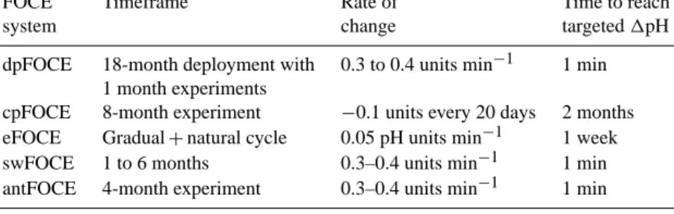
Table 3. Initial change in pH performed (or planned) during the different FOCE experiments.
FOCE Timeframe Rate of Time to reach
system change targeted 1pH
dpFOCE 18-month deployment with 0.3 to 0.4 units min−1 1 min 1 month experiments
cpFOCE 8-month experiment −0.1 units every 20 days 2 months eFOCE Gradual + natural cycle 0.05 pH units min−1 1 week swFOCE 1 to 6 months 0.3–0.4 units min−1 1 min antFOCE 4-month experiment 0.3–0.4 units min−1 1 min
The frequency for sensing should be based upon the abil-ity and accuracy of the sensors and upon knowledge of past environmental fluctuations at the study site. If the sensors, such as pH electrodes, are used for feedback control, higher sampling rates are required to provide rapid enough data for feedback decisions. Researchers need to have rapid access to the sensor data, ideally in real time, to ensure that the system is functioning properly and to identify extreme values.
3 Key sensors and scientific needs
FOCE experiments depend on careful monitoring and con-trol of the carbonate system. In addition, other parame-ters are typically monitored to examine various processes (e.g., metabolic rates). Because the sensor system is so criti-cal, in this section we discuss issues related to measuring “es-sential parameters” considered necessary for FOCE systems and “optional parameters” that may be required for specific applications.
3.1 Essential parameters 3.1.1 pH
Considering that a primary goal of FOCE systems is con-trol of seawater pH within experimental enclosures, pH sen-sors and their calibration protocols must be selected care-fully. Ocean acidification experiments involve pH perturba-tions of up to 0.4 pH units below ambient. Sensors with a pre-cision better than 0.003 pH units are required in order to have a good pH control. To date, FOCE systems have used poten-tiometric pH electrodes, which often exhibit significant drift with time due to diffusion of seawater into the KCl reference solution. Therefore, such electrodes require frequent calibra-tion and comparison with pH measurements from discrete water samples. The pH of discrete water samples can be ac-curately measured spectrophotometrically (accuracy ± 0.005 pH units; Table 4) or computed based on total alkalinity (AT) and total inorganic carbon (CT) measurements
(accu-racy ± 0.007 pH units; Table 5). The electrode used for con-trolling pH must be calibrated when the measured pH differs from the pH value estimated from discrete sample by more
than a threshold value (e.g., 0.05 pH units). Calibration is performed in the laboratory using buffers at a temperature close to in situ temperature as described by Dickson et al. (2007).
There are few commercially available potentiometric pH electrodes designed for underwater deployment with the re-quired precision and accuracy. One example is the Sea-Bird SBE 18 pH sensor, which uses a pressure-compensated glass electrode Ag / AgCl-reference probe to provide in situ mea-surements at depths up to 1200 m. The earlier version of this electrode was modified by MBARI to reach a preci-sion of 0.0003 pH units. The most recent commercial verpreci-sion reaches a similar precision. Both versions drift due to sea-water contamination of KCl reference buffer; therefore the accuracy varies depending upon the frequency of calibration and duration of deployment (drift decreases with time). As an alternative to the potentiometric electrode, an ion-sensitive field-effect transistor (ISFET) sensor can be used, such as the Honeywell Durafet™. The advantages of the ISFET include robustness, stability, and precision, which make it suitable for ocean pH measurements. An ISFET sensor has been incor-porated into the deployable SeaFET™package developed at MBARI and the Scripps Institution of Oceanography (Martz et al., 2010) and commercialized by Satlantic. SeaFET™ sen-sors have been successfully deployed in shallow-water appli-cations monitoring (Hofmann et al., 2011) and will be used in antFOCE (see Sect. 4.5). Current ISFET sensors are only deployable to a depth of ca. 70 m, but versions that can op-erate at greater depth are in development. A recent XPRIZE contest (http://oceanhealth.xprize.org) is helping spur the de-velopment of new ocean pH sensors, and it is anticipated that more options may become available soon.
3.1.2 Salinity, temperature, and dissolved oxygen Salinity and temperature are required to assess the carbon-ate system parameters and control pH (see Sect. 2.4). Dis-solved oxygen is a key parameter characterizing the envi-ronmental setting and can be used to assess net community production and respiration based on closed-chamber incu-bations. For example, community metabolism can be mea-sured by observing changes in oxygen levels in a temporarily closed FOCE enclosure. Photosynthesis–irradiance curves of
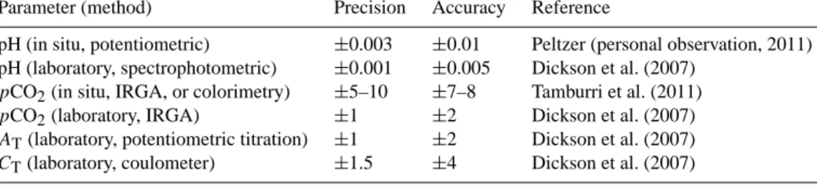
Table 4. Precision and accuracy of the measurements of carbonate chemistry parameters based on various in situ or laboratory techniques. pCO2is in µatm, ATand CTare in µmol kg−1. IRGA: infrared gas analyzer.
Parameter (method) Precision Accuracy Reference
pH (in situ, potentiometric) ±0.003 ±0.01 Peltzer (personal observation, 2011) pH (laboratory, spectrophotometric) ±0.001 ±0.005 Dickson et al. (2007)
pCO2(in situ, IRGA, or colorimetry) ±5–10 ±7–8 Tamburri et al. (2011)
pCO2(laboratory, IRGA) ±1 ±2 Dickson et al. (2007) AT(laboratory, potentiometric titration) ±1 ±2 Dickson et al. (2007)
CT(laboratory, coulometer) ±1.5 ±4 Dickson et al. (2007)
Posidonia seagrass communities in the bay of Villefranche
have been derived from changes in oxygen concentration measured during 24 h incubation with the eFOCE system (Fig. 3).
FOCE units should therefore be equipped with “conduc-tivity temperature depth” (CTD) instruments. Most com-mercial CTDs have specifications suitable for FOCE sys-tems, with accuracies for temperature and salinity better than 0.002◦C and 0.001, while typical drifts are about 0.0002◦C and 0.0001 month−1, respectively. Various optical oxygen sensors have successfully been tested in the field (see http: //www.act-us.info) and are commercially available. They typically exhibit a precision and accuracy of about 2 and 3 µmol kg−1respectively.
3.1.3 Additional parameter of the carbonate system The carbonate system can be characterized when at least two of its parameters are known (Zeebe and Wolf-Gladrow, 2001). Table 4 presents the precision, and accuracy of the different methods used to measure these parameters and Ta-ble 5 shows the errors associated with the computation of each parameter as a function of the pair of parameters mea-sured. Measuring pCO2 and pH continuously using in situ
sensors is attractive as it could provide a continuous charac-terization of the carbonate chemistry (with real-time temper-ature and salinity data; see Sect. 3.1.2). However, this pair of parameters leads to large uncertainties in the computation of the other parameters of the carbonate system (Table 5). It is therefore recommended to sample water in the experimental enclosures as well as in the external environment on a reg-ular basis (e.g., once a week or more if an automated sam-pling technique is available). Sampled seawater can be used to independently measure parameters of the carbonate sys-tem such as AT, CT, and/or pH. It should also be noted that
AT can be overestimated due to alkalinity associated with
dissolved organic matter, leading to significant errors in the derived parameters (Hoppe et al., 2012). Koeve et al. (2012) recommended to overdetermine the CO2 system in
experi-mental ocean acidification studies to safeguard against pos-sibly large errors in estimated pCO2. It is out of the scope of
this paper to detail all analytical procedures, and we refer the reader to Dickson et al. (2007) for a comprehensive
descrip-Table 5. Relative uncertainties in pH, total alkalinity (AT in
µmol kg−1), dissolved inorganic carbon (CT in µmol kg−1), and
partial pressure of CO2(pCO2) resulting from the uncertainties
(ac-curacies) shown in Table 4 (the in situ uncertainties are considered for pH and pCO2). These relative uncertainties have been computed as described in Dickson (2010), assuming uncertainties in tempera-ture and salinity in situ of 0.002◦C and 0.001, respectively.
Pair of parameters upH uAT uCT upCO2
pH – pCO2 – ±88 ±73 -pH – AT – – ±7 ±11 pH – CT – ±9 – ±10 pCO2– AT ±0.007 – ±5 – pCO2– CT ±0.008 ±8 – – AT– CT ±0.007 – – ±10
tion of the protocols. Instruments for continuous measure-ment of CTin situ have recently been developed (Liu et al.,
2013). AT can be measured continuously in the laboratory
(Li et al., 2013), but it is not clear when a system that can be deployed on the sea floor will be available.
3.2 Optional sensors and parameters 3.2.1 Net calcification
Ocean acidification is detrimental to the net precipitation of calcium carbonate (CaCO3) shells and skeletons by many
marine organisms (Gazeau et al., 2013; Kroeker et al., 2013). Net calcification is therefore an important process in FOCE experiments involving calcifying organisms. It can be as-sessed by collecting organisms, measuring their buoyant weight in the laboratory, and bringing them back in the enclo-sures. This approach is very time consuming and involves a lot of manipulation of the organisms. Calcification of the en-tire community can be measured using the alkalinity anomaly technique (Smith and Key, 1975) when the units are closed. This technique makes the assumption that the production of 1 mol of CaCO3decreases total alkalinity (AT) by 2 mol.
Since there is currently no total alkalinity sensor that can be deployed in situ, measuring the change in AT must
Figure 3. Measurements of the community metabolism of a Posidonia seagrass bed in the northwestern Mediterranean Sea performed in
the frame of the eFOCE project. Oxygen variations (A) and photosynthesis–irradiance curves (B) during incubations performed in closed-chamber conditions.
Calculating total alkalinity from pH and pCO2(the only two
parameters that can be conveniently and continuously mon-itored) leads to unacceptably large errors (±88 µmol kg−1; Table 5). In most cases, the increase or decrease of AT
gen-erated by the precipitation and dissolution of CaCO3is much
lower than the accuracy that can be achieved using measure-ments of only pH and pCO2.
Another non-destructive technique is to estimate net cal-cification rates from changes in CTduring incubations,
as-suming that CTis only controlled by net community
produc-tion (NCP) and net calcificaproduc-tion. NCP can be estimated using changes in the concentration of dissolved oxygen (see Sect. 3.1.2) converted to carbon units (e.g., Gattuso et al., 1999). Since this method is based on the measurements of two pa-rameters and on the use of a theoretical CT: O2ratio, it
pro-vides estimates with a relatively high uncertainty compared to the alkalinity anomaly technique.
3.2.2 Nutrients
Modifications in the functioning of benthic communities as a response to ocean acidification has the potential to signif-icantly alter nutrient cycling and the role of these commu-nities as the source or sinks of various elements such as ni-trogen and phosphate (Barry et al., 2011). In addition to the direct effects on rates of primary production and associated nutrient requirements, several laboratory experiments have demonstrated modifications of shallow sediment–water nu-trient fluxes due to the impacts of ocean acidification on the macroorganisms responsible for bioturbation and bioirriga-tion activities in the sediment (Barry et al., 2011). There-fore, the measurement of macronutrients (nitrate, ammo-nium, and phosphate) changes during closed incubations ap-pear of great interest. Sensors allowing for the continuous measurement of nitrate in situ have been developed since the 1980s (Johnson et al., 1989). Available commercial sen-sors currently reach a precision and accuracy of respectively 0.5 and 3 µmol L−1(see http://www.act-us.info/evaluations. php). Although this could be sufficient for highly active
com-munities, in most cases, laboratory measurements of discrete samples must be performed.
3.2.3 Light
FOCE systems deployed in the euphotic zone benefit from having photosynthetically active radiation (PAR) sensors inside the enclosures in order to relate the community metabolism to irradiance. A surface PAR sensor is also use-ful to model the optical characteristics of the water column. Ultraviolet sensors are also optional sensors if UV is a pa-rameter of interest at the study site and if partial confinement is achieved by UV-transparent material.
3.2.4 Camera
Imagery is not necessary for operating a FOCE system but it can be useful for monitoring the status of the system and make scientific observations. Cameras allow for non-destructive collection of data, such as changes in the den-sity and composition of epifaunal and epifloral communities, as well as behavioral responses of conspicuous species. Ide-ally camera observations should be via continuous video, but time-lapse photography can also be appropriate.
Very simple techniques can be employed to make inexpen-sive cameras. For example, the Linksprit™is a single-board camera with a very small footprint and several lens options. It comes with open source software and can easily be interfaced with Arduino™computer boards. Another approach for ad-ditional performance is to use off-the-shelf security cameras which have additional features, such as pan and tilt, but these are more costly. Both types of cameras require a simple hous-ing for submerged operations. Underwater cameras are avail-able, but the cost of a full-featured system can be prohibitive for FOCE experiments.
3.2.5 Flow measurements
Water flow influences virtually all aspects of the biology of marine benthic organisms. Hydrodynamics has wide-ranging
roles. For example, it controls the availability of nutrients and food particles and also affects the dispersion of gametes (Vo-gel, 1994). Flow measurements can therefore be extremely useful in a FOCE system, and it is crucial to maintain a flow regime in the enclosures similar to ambient. Even if the sys-tem is only partly open, the structure will limit natural flow patterns, affecting processes from molecular exchange rates to the transport of waste (i.e., mussel beds) or export of dead leaves (seagrass and macroalgae). This could influence the results obtained in the enclosures and limit upscaling of the results to natural ecosystems.
Flow can be monitored using instruments such as acous-tic Doppler current profiler (ADCP), acousacous-tic Doppler ve-locimeter (ADV), or cheaper instruments. Fans or water pumps integrated into the FOCE design can achieve the sim-ulation of environmental flow rates. Replication of average flow rates is reasonably easy in areas with moderate flow en-vironments. However, maintaining very large flow rates is challenging. It is also an issue to maintain very slow flow rates due to the equilibration of the carbonate system in the enclosure (low-pH spikes).
3.2.6 Sensor biofouling protection
For longer-term experiments, biofouling protection is neces-sary to limit the growth of organisms that can alter sensor function. If possible, mechanical biofouling protection such as rotating brush or plate is preferable but often more ex-pensive. Chemical biofouling protection such as copper or tributyl tin is commonly used in instruments such as CTDs, O2 sensors, and pH sensors, but care must be taken not to
place them within the enclosures, where the chemicals could affect the organisms inside. When instruments with chemical biofouling protection are used, it is recommended to include them in a pumping system that pulls the water from the en-closures through the instruments and then disposes the water well away from the experimental area.
4 Past, current, and planned FOCE implementations The main characteristics of the past, current, and planned FOCE systems are summarized in Table 1.
4.1 Deep FOCE (dpFOCE)
A FOCE system for studies of deep-sea benthic commu-nities (designated dpFOCE; Fig. 4a) was developed by MBARI. The dpFOCE project, deployed at a depth of 880 m, was attached to the Monterey Accelerated Research System (MARS) cabled seafloor observatory in Monterey Bay, cen-tral California, approximately 52 km from Moss Landing, where the cable makes landfall. The system used a flume con-cept where the pH offset vs. ambient seawater was monitored to maintain control of CO2 enrichment within the
experi-mental enclosure, while allowing access to natural seafloor
sediments and suspended particulate material. Time-delay wings attached to either end of the dpFOCE enclosure al-lowed for injection of CO2-rich seawater into either end
de-pending on the direction of near-bottom currents, and pro-vide sufficient time for full hydration of the injected CO2
-enriched seawater before entering into the experiment enclo-sure. Fans were integrated into the dpFOCE design to control water flow through the experimental enclosure and to simu-late typical local-scale flow conditions. Multiple sensors (pH, CTD, ADV, and ADCP) used in conjunction with the fans and the enriched seawater injection system allowed for the control loop software to achieve the desired pH offset. The dpFOCE system was connected to shore via the MARS ca-bled observatory, which provided power and data bandwidth. Enriched CO2seawater was produced from ambient seawater
flowing under a pool of liquid CO2held in a small container
near the dpFOCE enclosure; dissolution of liquid CO2 into
the seawater stream produced a CO2-rich mixture used for
injection into the dpFOCE enclosure. The dpFOCE system operated over 17 months and verified the effectiveness of the design hardware and software (Kirkwood et al., 2011). The dpFOCE has performed a number of long-term (4-week) pH control tests and has also proven to be an ideal platform to explore sublethal effects on animals that may be observed as changes in typical movement, posture, and feeding rates (Barry et al., 2013).
4.2 Coral Proto FOCE (cpFOCE)
A shallow-water FOCE system that could be deployed in coral reef habitats was developed at the University of Queensland. The cpFOCE system used replicate experimen-tal flumes to enclose sections of a coral reef and dose them with CO2-enriched seawater using peristaltic pumps with
computer-controlled feedback loops to maintain a specified pH offset from ambient conditions (Fig. 4b). The system was powered by solar and wind energy and the data were trans-mitted to a nearby laboratory for real-time monitoring and data management (Marker et al., 2010). A cpFOCE enclo-sure had forward and rear flow conditioners on either end to accommodate bidirectional ocean currents. The openings were placed parallel to the dominant axis of tidal currents over the reef flat, and each enclosure was anchored with sand stakes. The flow conditioners were attached to maximize tur-bulence and to provide passive mixing of the CO2-enriched
seawater. Four of the tubes in the flow conditioners furthest from the enclosure had small holes along their length through which low-pH water was pumped to dispense it evenly along the entire width and height of the conditioner. The cpFOCE system was deployed at Heron Island (Great Barrier Reef) to investigate the response of coral communities to ocean acid-ification (Kline et al., 2012) and an 8-month experiment was performed.
Figure 4. (A) Deep-water FOCE (dpFOCE), (B) Coral Proto FOCE (cpFOCE), and (C) European FOCE (eFOCE). Credits: (A) MBARI, (B, D, I) Kline (Scripps Institution of Oceanography), and (C, D) Luquet (CNRS-UPMC).
4.3 European FOCE (eFOCE)
The European FOCE (eFOCE, http://efoce.eu) is currently in the initial deployment stage and comprises two enclosures (control and experimental) as well as a surface buoy housing the electronics and pumps to produce CO2-enriched water
(Fig. 4c). The system is powered by solar and wind energy. Data are sent to the nearby laboratory and can be monitored on the internet. The eFOCE system is currently deployed in the bay of Villefranche-sur-mer (France) at about 12 m depth and 300 m offshore. The eFOCE project was developed to investigate the long-term effects of acidification on benthic marine communities of the northwestern Mediterranean Sea, especially Posidonia seagrass beds. Over a 3-year period, the aim of the project is to perform a relatively long (> 6 months) experiment.
4.4 Shallow-water FOCE (swFOCE)
In collaboration with Hopkins Marine Station and the Cen-ter for Ocean Solutions, MBARI is developing a swFOCE system to examine the effects of ocean acidification on shal-low subtidal communities in central California. The swFOCE system will use a shore station for the seawater control sys-tem and production of CO2-enriched seawater, and will also
use an existing cabled observational and research platform to connect the swFOCE node. Initially, two swFOCE en-closures will be installed at a depth of 15 m, approximately 250 m offshore from Hopkins Marine Station. The nearby node of the cabled observatory (Kelp Forest Array) has
in-struments to monitor local currents, temperature, pH, and O2
in real time, and serves as a cabled observatory platform for scientific research.
4.5 Antarctic FOCE (antFOCE)
The first polar FOCE, antFOCE, experiment was proposed and awarded funding in November of 2012, followed by design and concept work in 2013 (Fig. 5) and engineering tests before deployment in 2014. The antFOCE units will be placed on the seabed near Casey Station, East Antarc-tica (two control experimental enclosures and two high-CO2/low-pH experimental enclosures). One of the
difficul-ties with deploying FOCE infrastructure in a polar region is both sea ice and fast ice. To circumvent issues with ice, sci-entific divers will deploy each unit through the sea ice early in the Antarctic summer field season and the units will be re-trieved in open water conditions late in the summer. Connect-ing the sea-floor units to topside power (through sea ice or open water) will be achieved with a purpose-designed heated ice buoy to avoid land, fast ice, and freezing of the sea-water in the in/outflow.
5 Future developments
As FOCE technology matures, one will be increasingly faced with the decision of which communities to target and where to locate new FOCE experiments, both in terms of comple-menting existing FOCE research and expanding into areas
Figure 5. (A) antFOCE site (O’Brien Bay, Antarctica); (B) simplified sketch of the antFOCE system. Credits: (A) G. Johnstone (AAD) and (B) W. Kirkwood (MBARI) and J. Reeve (AAD).
of particular concern, including regions of high biodiversity; those providing key economic, cultural, and/or ecosystem services; or those that are particularly sensitive. Key loca-tions could also be identified in order to benefit from estab-lished infrastructure and ocean acidification monitoring pro-grams. While ocean acidification is of global concern, up-welling regions, coral reefs, and polar areas are especially sensitive to ocean acidification (Gattuso et al., 2011) and are therefore good candidates for FOCE experiments.
Areas of particular difficulty for FOCE experiments in-clude regions of heavy wave action, large tidal currents, and rapid flow, as well as those of heavily polluted, disturbed, or unstable sediments. To increase the likelihood of success for future FOCE experiments, we recommend partnering with marine science institutes having the multidisciplinary exper-tise and infrastructure necessary to undertake such activities. The ocean acidification community recently emphasized the need to investigate the combined effects of ocean acid-ification and other environmental drivers (Hoegh-Guldberg and Bruno, 2010; Boyd, 2011). Two other major global drivers are ocean warming and the spreading of hypoxic zones where the concentration of dissolved oxygen is lower than 60 µmol kg−1 (Hofmann et al., 2011). The
combina-tion of global warming, ocean acidificacombina-tion, and hypoxia can have additive, synergistic, or antagonistic effects on organ-isms’ performances (Boyd and Hutchins, 2012), advantaging or disadvantaging some species or group of species (e.g., cal-cifiers, fleshy autotrophs) to the detriment of others, affecting the distribution of species and ultimately leading to ecosys-tem shifts. For example, in tropical regions, the coincidence of warming and acidification is expected to cause shifts from coral reefs to seagrass- and seaweed-dominated ecosystems (e.g., Diaz-Pulido et al., 2011; Fabricius et al., 2011). In tem-perate areas, the same drivers are expected to cause shifts from forests and meadows of perennial algae to mats of
ephemeral and opportunistic algae such as turfs (Connell and Russell, 2010).
Very few experiments have considered warming, acidifi-cation, and hypoxia together, and all were performed in the laboratory. To date, no FOCE experiment has controlled a parameter other than the carbonate system. While FOCE sys-tems are being developed and deployed, and their data ana-lyzed, it is important to develop the next generation of FOCE systems that should be able to manipulate multiple variables. For example, to simulate warming and hypoxia as offsets from ambient values.
Manipulating the temperature of underwater optop en-closures seems unrealistic because it would require large amounts of energy due to the high thermal conductivity of seawater, the “infinite” thermal capacity of the ocean (at the scale of a FOCE system), and the enhanced outflow of seawater at the top of the enclosure due to the increased buoyancy of warmer water. Temperature control would there-fore require enclosing seawater much more than the current FOCE systems do. Early calculations suggest that simultane-ous control of pH and temperature can be accomplished, with closed enclosures of 0.25 m3 flushed once every hour, and
higher operational electrical costs (Mahacek, unpublished data). Cross-flow heat exchange techniques can be used to significantly reduce the heating energy requirement.
Hypoxia can be simulated with the injection of O2
deprived seawater (e.g., 60 µmol kg−1). O2 can be
de-creased in an intermediary reactor by physical outgassing, through the injection of N2 (g), or by chemical scavenging
through the injection of sulfite ions. Although toxic, sul-fites rapidly react with O2 to produce sulfate ions (Wong
and Zhang, 1992). Surface seawater O2 concentration is
about 230 µmol kg−1 (at a salinity of 35 and tempera-ture of 20◦C) and the depletion to 60 µmol kg−1 will gen-erate approximately 170 µmol kg−1 sulfate ions, which is negligible compared to the natural seawater concentration
(ca. 28 mmol kg−1at a salinity of 35). Unlike for pCO 2and
temperature, the concentration of dissolved oxygen can be easily increased to simulate preindustrial concentrations by direct injection of O2(g) into the reactor. Designs for
manip-ulating oxygen are underway at MBARI and a future upgrade of the swFOCE system is planned in order to control the con-centration of dissolved oxygen, in line with the expected ex-pansion of a dead zone in Monterey Bay.
6 Building a community of FOCE users: the xFOCE approach
xFOCE is an open source package of plans and software de-veloped at MBARI to make the design and fabrication of FOCE systems more accessible to a wide range of ocean acidification researchers (http://www.xfoce.org; Kecy et al., 2013).
Developing new systems for in situ experiments can be ex-pensive, and requires time and expertise to develop. xFOCE provides reference designs at no cost to enable users to de-velop a simple application relatively quickly, and to refine those designs as research questions evolve. The key elements of xFOCE reference designs include modularity, robustness, ease of use, and adaptability. While it is not possible to build a single solution suited to every possible FOCE experiment, the developers goal has been to provide fundamental build-ing blocks that are easily used and modified to suit many configurations. Designs will include a system for delivering CO2 enriched seawater, a modular experimental enclosure
and anchoring system, a power distribution system for a ca-bled observatory, and electronics and software for collecting data and controlling the FOCE instrument.
7 Overarching activities
A globally coordinated network of FOCE experiments in re-gions known to be particularly at risk of increasing CO2
absorption, from the tropics to the poles, in partnership with leading FOCE technology specialists, will contribute the kind of community-scale information required to influ-ence ocean research, policy, and technology agendas to bet-ter manage at-risk marine communities and regions in the high-CO2future. In order to successfully build an efficient
and sustainable long-term FOCE network, it will be useful to put into place a number of joint overarching activities alongside the purely scientific work associated with each in-dividual FOCE system. Examples of such activities are ca-pacity building, communication, and effective management of the data that will emerge from the network. These activi-ties will need a strong collaborative effort among the various xFOCE partners and should be organized taking into account existing efforts and opportunities for coordination with other projects and initiatives. Experience from past multinational projects such as the European Project on Ocean
Acidifica-tion (EPOCA) has shown the added value of such activities, e.g., in terms of creating a collaborative work atmosphere and adding to the integrity and legacy of the project. 7.1 Capacity building and collaboration
Training and capacity building are of particular importance for the xFOCE network, especially during its initial build-up phase, due to the complex technology involved. Proper training and knowledge transfer is important for data qual-ity assurance and comparabilqual-ity. It would be beneficial to plan for scientists and engineers within the network to visit one or several of the other FOCE setups in order to increase knowledge transfer, promote problem solving, and encour-age opportunities of collaboration. This has been done on an ad hoc basis so far, especially for engineers, but no spe-cific funding source has been identified as yet. If possible and practicable, it would also be valuable for scientists and stu-dents outside the network to visit FOCE facilities to receive training and initiate collaborations so as to increase the po-tential of widening the network and maximizing the use of the technique. Two workshops bringing together FOCE net-work partners were organized in 2012 and 2013. The meet-ings brought together about 20 scientists and engineers and provided an opportunity to present recent progress and the next generation of systems, discuss difficulties encountered, common pitfalls, and best practices, as well as overarching network activities such as data management and outreach. It is hoped that these annual meetings can continue to facilitate the development of the network.
7.2 Intercomparison exercises
Intercomparison exercises are an important means to achieve quality assurance and control at a network level. It would be advantageous for the FOCE community to organize in-tercomparison exercises between the different FOCE units. Such exercises would allow for comparisons of results emerging from the different systems and ensure data quality. 7.3 Data management
The real-time data collection in FOCE experiments gener-ates a relatively large amount of information. Large data sets are not unique to FOCE experiments and are ef-fectively dealt with, for example, by the ocean observ-ing community. It is important to ensure robust data qual-ity assurance through a common data policy and data reporting guidelines for all FOCE systems participating in the network. Care will be taken to ensure appro-priate FOCE representation and integration with existing and emerging efforts on the compilation and archiving of ocean acidification data, for example the data compila-tion of the Ocean Acidificacompila-tion Internacompila-tional Coordinacompila-tion Centre (OA-ICC; Nisumaa et al., 2010; http://www.iaea. org/ocean-acidification/page.php?page=2195), and through