Control of Multi-Module Nuclear Reactor Stations by
Matthew Jay hor
B.S. Nuclear Engineering, University of Virginia (1985)
SUBMITTED TO THE DEPARTMENT OF NUCLEAR ENGINEERING
IN PARTIAL FULFILLMENT OF THE REQUIREMENTS FOR THE DEGREE OF
MASTER OF SCIENCE IN NUCLEAR ENGINEERING
at the
MASSACHUSETS INSTITUTE OF TECHNOLOGY February 1986
Massachusetts Institute of Technology 1986
Signature of Author
Certified by
Certified by_
Signature redacted
Department of Nuclear Engineering December 11, 1985
Signature redacted
I(I
Michael J. Driscoll Thesis SupervisorSignature redacted
Signature redacted Accepted by David D. Lanning Thesis Supervisor Allan F. Henry Chairman, Departmental Committee on Graduate StudiesMASS OF TCOLOGyH E S INSTITUTE
APR
04 1986
LIBRAPAES
Control of Multi-Module Nuclear Reactor Stations
by
Matthew Jay Schor
Submitted to the Department of Nuclear Engineering on December 11, 1985 in partial fulfillment of the requirements
for the Degree of Master of Science in Nuclear Engineering Abstract
Technological and regulatory issues associated with the control of multi-module nuclear reactor stations have been examined. Applicable technologies from other related industries have been investigated, and their impact on a power plant control system design are discussed.
The new technologies which promise to have the most effect on a multi-module control system are: fault tolerant processors, sensor fault tolerance techniques, artificial intelligence in the form of real time 'expert systems', and fiber optic communications. A control system incorporating these features would be highly automated, extremely reliable, and require a minimum number of operators.
A candidate configuration employing the above components is presented for discussion purposes, and aspects requiring further clarification are identified.
Thesis Supervisors: Dr. David D. Lanning
Title: Professor of Nuclear Engineering Dr. Michael J. Driscoll
Multi-Module Control
Acknowledgements
This work was supported under a research contract with the General Electric Corporation as part of their Department of Energy sponsored efforts on advanced reactor development. Work performed in the fall of 1985 was
supported by the Department of Energy through a fellowship in Nuclear Engineering.
The author would like to thank Professor Michael Driscoll and Professor David Lanning for their guidance and helpful insight throughout the entire research effort.
The author also gratefully acknowledges Dr. John Hopps, of the Charles Stark Draper Laboratories, for the information on the Advanced Information Processing System. The author would also like to thank Bruce Bodnar of Northeast Utilities for his generosity in taking his own time to explain, in detail, the state of control technology at Millstone Unit 3. Also, the engineers and managers at Lisp Machine Incorporated were extremely helpful in their
description of PICON, and real time artificial intelligence systems. Finally, W. R. Daniel of the General Electric Company is thanked for his input.
The control system described in this report is presented for discussion purposes only, and is not necessarily the best design or the only possible one for a multi-module nuclear power plant. In particular, it should not be construed as critical of specific features under development by General Electric for their
PRISM reactor.
Table of Contents Page A bstract ... . 2 Acknowledge me nts ... 3 Table of Contents ... 4 List of Figures ... 6 List of Tables ... 7 Chapter 1 Introduction 1.1 Foreword ... 8 1.2 Background ... 9
1.3 Organization of this Report ... 9
Chapter 2 Control Technology: State of the Art and Practice 2.1 Introduction ... 11
2.2 Nuclear Applications 2.2.1 Regulatory Constraints... 14
2.2.2 United States Practice - Millstone Unit 3...15
2.2.3 Foreign Practice - Canada & Japan...18
2.3 Non-Nuclear Applications 2.3.1 Chemical Process Industry - Artificial Intelligence...23
2.3.2 Aerospace Applications... 32
2.4 Chapter Summary ... 36
Chapter 3 Review of New Technology 3.1 Introduction ... 37
3.2 Systems & Components 3.2.1 Data Communication and Analysis...39
3.2.2 Fault Tolerant Computers... 41
3.2.3 Information Display Technology... 46
3.3 Human Factors Considerations ... 49
3.4 Chapter Summary ... 54
Chapter 4 Conceptual Features of a Multi-Module Control System 4.1 Introduction ... 55
4.2 Multi-Module Power System Description 4.2.1 LMR System Characteristics - PRISM & SAFR... 56
4.2.2 MHTGR Sytem Characteristics... 61
Multi-Module Control 5
Table of Contents (continued)
Chapter 4 Conceptual Features of a Multi-Module Control System (continued)
4.3 Relation of Passive Safety Features to Control ... 69
4.4 Generic Control Issues 4.4.1 Architecture of Control System... 70
4.4.2 Start Up / Steady State / Transient Conditions... 73
4.4.3 Accident & Post-Accident State Control... 75
4.4.4 Level of Redundancy... 76
4.4.5 Degraded-State... 79
4.4.6 Degree of Automation & Hardwiring... 81
4.4.7 Credit for Demonstrability... 83
4.4.8 Nature and Degree of Unit Interconnections...84
4.5 Control System Design Standards ... 85
4.6 Unresolved Issues Affecting Licensability ... 86
4.7 Chapter Summary ... 87
Chapter 5 Summary, Conclusions and Recommendations 5.1 Summary and Conclusions ... 88
5.2 Recommendations ... 91
List of Figures
2.1 PICON Architecture ... 25
2.2 Establishing Attributes for Icons ... 27
2.3 Catalytic Cracker ... 29
2.4 Creating a Rule ... 30
3.1 Pair and Spare Strategy ... 43
3.2 AIPS Proof-of-Concept Configuration ... 45
4.1 PRISM Configuration ... 57
4.2 SAFR Configuration ... 60
4.3 MHTGR Primary System, Pebble Bed Core ... 63
4.4 MHTGR 'Side by Side' Configuration ... 65
4.5 Proposed SP-100 Configuration ... 67
4.6 Top Level Architecture of Control System ... 70
4.7 Module Level Architecture of Control System ... 71
Multi-Mcxlule Control 7
List of Tables
Page 2.1 Relevance of Control Applications
to a Nuclear Power Plant ... 11
3.1 Recommended Color Codes ... 51
3.2 Recommended Values for Information Density ... 52
4.1 Safety Characteristics of SAFA ... 59
4.2 MHTGR Design Goals ... 61
4.3 Applicable Standards for Control of Safety Systems ... 85
Chapter 1 Introduction
1.1 Foreword
The current emphasis on small, inherently safe, modular nuclear power plant designs which rely upon passive means for decay heat removal has led to the consideration of digital computers for active control of the entire power plant.
The relatively low thermal power of individual modules necessitates coupling several units to a single turbine / generator for the economic operation of the plant. Up to five modules (reactor plus steam generator) will feed a single turbine, and there may be as many as three or four of these combined units operating at one site. Thus up to twenty modules (100 MWe per module) may be at a single site.
This multitude of modules makes the use of digital computers for plant control almost mandatory. If conventional control methods were employed, there could be a total of 80,000 control signals and operating parameters to be
monitored and processed. If each module were to have its own complete control room with the usual complement of operators, the cost of both
constructing and operating the plant would make multi-modular power plants prohibitively expensive. New process control and data processing techniques must be intelligently applied in order for the dis-economies of scale to be offset for this smaller design.
Multi-Module Control
1.2 Background
Direct digital control of nuclear power plants has not been practiced in the past in the United States. Only recently have U.S. researchers begun to apply digital control to nuclear reactor control, and this has been done only on small research reactors. The application of digital computers to power plant control will only occur if the reliability of computer-based systems is increased
and if regulatory agencies revise their current position on such use.
The reliability and availability of computers can be increased through a variety of fault tolerant techniques developed for the industrial use of computers. Additionally, the 'reliability' of the control software is being increased through
advanced programming methods that allow the power plant design engineer to
'program' the computer without the need to learn the programming language or having a computer programmer do the job. This eliminates the previously error prone step of having the design engineer communicate the description of the power plant to the programmer. These methods, which promise to increase the reliability of the digital computer, will enable the computer to become fully qualified for nuclear power plant control.
1.3 Organization of this Report
Non-nuclear industries are under a different set of constraints than the nuclear industry, and are thus able to apply the latest in control technologies to their specific needs. A survey of a variety of industries ranging from aircraft to chemical plants was performed in order to identify which industries are most closely related to nuclear power plant control. The most closely related industries with the furthest advanced control techniques were chosen, and descriptions of their control systems appear in Chapter 2.
In Chapter 3 new technology that can be combined with the control technologies described in Chapter 2, is reviewed. Fault tolerant processors, fiber optic networking, and data analysis techniques are described.
Additionally, a few examples of new display technologies which promise to improve the man-machine interface are reviewed, and a few relevant human factors considerations are discussed.
In Chapter 4 all these technologies are brought together in a description of a possible multi-module digital control system. Various questions are
identified which need to be answered before advanced work can proceed on development of such a control system, as discussed in Chapter 5 in the summary and recommendation sections.
Multi-Module Control
Chapter 2
Control Technology: State of the Art and Practice
2.1 Introduction
In order to identify control technologies relevant to multi-modular nuclear power plants, a survey of the state-of-the-art of control technologies in other industries was performed. Applications that received in depth studies were ones that had characteristics most resembling those of a nuclear power plant from a control viewpoint, namely large investment, accident severity, complexity, multi-modularity, number of control signals, operating conditions, and response time domain (e.g. milliseconds vs. hours). Table 2.1 lists applications that were initially considered, and rates each category (qualitatively) on a scale of one to four, where four correlates best with a nuclear power plant.
Table 2.1
Relevance of Control Applications to a Nuclear Power Plant
C 4) 2 4-. 0 4) C Application 4-, L 4) 4) 4-, C 4) U 4-, 4) 0. 2 0 C-) 4-L. 0 .5 0 z ~0-~ .5 0 0 C 0 I.. C 0 0 0 0 C 0 C 0 C-) C 0 L 4) 0. 0 E 0 2 Multi-Engine Aircraft 2 2 2 2 1 1 1 Space Shuttle 3 1 3 2 2 1 1 U.S.S. Enterprise 2 2 4 4 3 4 4 Fly-by-Wire Aircraft 2 1 2 1 2 1 1
Fossil Power Plants 2 3 2 3 2 3 3
Chemical Plants 4 4 3 3 4 3 3
Space Nuclear Power 2 1 2 1 1 4 4
Multi-engine aircraft are only superficially multi-modular in the sense of multi-modular nuclear power plants because the engine is basically either off or on. Some comparison might be made relative to power control wherein the aircraft engine is controlled by local controllers and the pilot merely sets the required power. There are some other aspects of aircraft technology that are applicable, particularly in the area of sensor fault identification, as is
demonstrated by a microwave landing system developed for a Boeing 737. The Space Shuttle is almost completely digital computer controlled, but it is in a totally different time domain than a nuclear power plant. That is, many decisions need to be made so quickly that they can only be done by a
computer. However, like multi-engine aircraft, there are also relevant sensor fault techniques used.
Digital Fly-by-Wire supersonic aircraft such as the X-29 or F-1 6 also must be controlled by a computer because they are unstable and adjustments must continuously be made to the control surfaces in order for the aircraft to fly stably. Again the time domain of these aircraft is much shorter than nuclear power plant control, and thus less applicable. Also, detailed technical information is
classified.
The aircraft carrier U.S.S. Enterprise is perhaps the most related to a multi-modular nuclear power plant since it has eight reactors on board (with two reactors per propeller shaft1) and four control rooms. However, since it was the first nuclear powered aircraft carrier (launched in 1960) the degree of digital computer control is probably not high, and, like the F-1 6, technical information is classified.
Multi-Module Control
Fossil-fired power plants, especially gas turbines, are multi-modular, but they interconnect only at the switchyard. In addition, the degree of computer control is not high enough to warrant further study.
By far the most applicable case discovered was found in the chemical
process industry. A computer system has been developed that combines artificial intelligence capabilities with fast data collection to create an expert system process control advisor. It is being applied to oil refinery control, and is
likely to be the most advanced application of artificial intelligence relevant to multi-modular nuclear power plants.
To put these technologies in perspective, a nuclear power plant nearing completion was investigated with respect to its process computer and data transmission techniques. Finally, the Japanese and Canadian experience with automatic control was investigated, since these countries are not under the same regulatory constraints and have applied automatic control to a much greater extent.
2.2.1 Regulatory Constraints
The nuclear regulatory environment is a conservative one. This conservatism requires that any system needed for the safe shutdown of the
plant (safety related), or is associated with a safety related system, must go through an exhaustive quality control test. Traditionally this has meant that only proven technology could be employed in safety systems. As a result, utilities have shied away from using sophisticated digital computers because it is next to impossible to fully test their software. An extension of this philosophy led to a
policy of not allowing a digital computer to actively control a nuclear reactor core. However, this situation is slowly changing as is illustrated by experiments on the Massachusetts Institute of Technology's research reactor. A computer with sensor fault tolerance controlled the position of the reactor's regulating control rod.2 And, in the safety area, a digital computer on Arkansas Unit 1 continuously calculates various reactor core safety limits, and when one of them
is exceeded the reactor scrams.3 Despite these advances, the regulatory climate remains conservative and currently excludes, with few exceptions, the use of digital computers in either an active safety or operational role.
2 A. Ray, M. Desai, J. Deyst, "Fault Detection and Isolation in a Nuclear Reactor," Journal of Energv Vol. 7, No. 1, (January - February 1983). Page 79.
Multi-Module Control
2.2.2 United States Practice - Millstone Unit 3*
The Millstone 3 Nuclear Power Plant was selected in order to investigate, in the shortest amount of time, the state of control technologies at current power
plants. Millstone 3 was chosen because the plant is scheduled to come online
in May of 1986, it is nearby, and because of the researcher's familiarity with the plant. The plant is an 1150 MWe Westinghouse PWR, to be operated by
Northeast Utilities. The plant process computer is of particular interest since it is
considered by some to be the most advanced at an existing nuclear power
plant.
The Millstone 3 process computer is a ModComp Classic-32 computer (ModComps are used for ground control of the Space Shuttle) with two identical central processing units (hosts), and two satellite computers associated with each host for preprocessing of data. The system has 4000 digital inputs and 2000 analog inputs, almost all of which are hardwired into the satellites. The system is purely a display device and serves no control functions. Its most
sophisticated function is as part of the Safety Parameter Display System
(SPDS). SPDS is similar to expert systems in terms of inference ability in that it measures various plant conditions to determine if certain accident scenarios are
occurring. For example if there is a leak in the primary coolant system it will account for all sources and sinks (letdown, makeup, coolant pump seal
leakage), calculate the difference, check to see if the containment sump level is rising at a corresponding rate, and if all conditions exist it will signal a primary leak. However, SPDS is less sophisticated than expert systems since it is programmed in FORTRAN and thus needs the services of a skilled programmer
The information presented in this section resulted from an interview with Bruce Bodnar, Computer Operations Dept., Northeast Utilities in July, 1985.
for development and modification. Nevertheless, SPDS does offer simple sensor fault detection (analytic and sensor redundancy) with a more advanced
information display system than that of simple annunciators and meters.
The process computer was designed to be dual redundant with respect to hardware and software. Each host is capable of processing six application
programs concurrently in addition to the scan and alarm programs. If one host fails the programs 'fail over' to the other host. The two satellites that preprocess the data are similarly configured in that each has the capability to process all of
the data. The satellites are fed by data multiplexors which gather data from termination cabinets outside of the computer room. The multiplexors are not
redundant and thus are susceptible to single mode failure.
In addition to the protection afforded by this dual redundancy some parts of the process computer are, in a sense, distributed. The radiation monitor subsystem is controlled by dual redundant PDP-i 1's and the flux mapping subsystem is microprocessor (Intel 8085) controlled. These subsystems are serially linked (RS-232) to the process computer. The most advanced data link at the plant is to the Inadequate Core Cooling system.
The Inadequate Core Cooling (ICC) system consists of several systems such as the subcooled margin monitor and the reactor water level system (Combustion Engineering heated junction thermocouple). The data from the
ICC is multiplexed over a fiber optic line to the process computer.
The process computer also is replacing some of the control board in the sense that not all of the data that is fed to the computer appears on the control board. For instance if there is a fire in a certain part of the plant, the 'Fire Area
Multi-Module Control
A' annunciator lights on the control board and the operator has to query the
computer for more detailed information.
It is important to recognize how the utility views the process computer from the regulatory viewpoint. Northeast Utilities considers the process
computer to be 'quality related'. That is, it is useful for the economic operation of the plant. If the process computer with its associated hardware and software were to be classified as safety related, Northeast Utilities feels it would be impossible to apply conventional quality control procedures to the computer.
Overall, the degree of technology at Millstone is very advanced in a few subsystems, i.e. the plant computer is state of the art, but it is not allowed to control any device. Any critical control functions are served by proven technology such as PID loops; a circumstance which can be attributed to a variety of reasons ranging from the conservatism of the plant's owner/operator to the perceived difficulties of shepherding such a complicated system through the regulatory process.
2.2.3 Foreign Practice - Canada & Japan
Foreign nations have proceeded further with automatic digital control for nuclear power plants than the United States because of their different
regulatory climate. Canada and Japan are prime examples since both have made extensive progress to date. Canada has used digital computers for control since the CANDU (CANadian Deuterium Uranium) reactor was first developed in 1966.5
The CANDU computer control system is used for numerous purposes including the vital functions of: alarm annunciation, data display, reactor power control, primary heat transport system pressure control, steam drum pressure control, and steam generator level control. Allocating these functions to the computer resulted in a 40% reduction in the numbers of meters and recorders in the control room.6
The computer uses alarm conditioning to suppress alarms, except the primary alarm, which result from an event such as a power loss. In addition, alarm reports are sorted in order of priority. These techniques reduce operator confusion.
The control system is supervised and run by two independent identical minicomputers used in a redundant fashion; and each computer has been
found in practice to have an availability of over 99%. While neither is capable of running all applications individually, they are able to run all vital functions for normal plant operation should one fail. If this occurs the computer that was in a 'hot standby' mode takes over control of the plant. These computers are
5 E. M. Hinchley, et. al. "The CANDU Man-Machine Interface and Simulator Training," Chalk River Nuclear
Laboratories, Ontario. AECL-7768, (Sept. 1982). Page 2.
Multi-Module Control
independent of the safety system, and all safety systems are controlled by hard-wired logic systems, not digital computers. This situation may change since a computer based system called the "Intelligent Safety System" is being
developed at the Chalk River National Laboratories.7
The Intelligent Safety System (ISS) is being developed because existing shutdown systems, which contain 87 sensors, are difficult to test, and because plant operators would benefit by a computer display of the shutdown system status. The ISS design is based on a supervisory computer (such as a
ModComp CLASSIC-32) and three safety computers (DEC PDP-1 1/55's) for numerical processing of the data. The safety computers contain algorithms for sensor fault tolerance and an algorithm which estimates the maximum fuel channel power via a diffusion theory reactor physics calculation. This fuel channel power is then compared to the maximum allowed for the fuel design,
and if the margin is too small the reactor trips. The software for the safety computers is written in RATFOR (RATional FORtran). Software for the
supervisory computer has not been developed yet (July, 1984).8 This system is notable for its distributed architecture, which is directly applicable to multi-modular control system design.
The possible future of control systems for the CANDU was described in a
1978 report entitled: "Distributed Computer Control Systems in Future Nuclear
Power Plants"9 This report specifies that the transmission medium for
distributed control systems will be based on cable television (CATV), possibly followed by fiber optics. It is interesting to note that it only took 7 years for fiber
7 J. A. Hall, et. al. "The Intelligent Safety System: Could it Introduce Complex Computing into CANDU
Shutdown Systems?,"Chalk River Nuclear Laboratories, Ontario. AECL-8561, (July 1984).
8 Ibid 5, Page 4.
9 G. Yan, J.V.R. L'Archbveque, L.M. Watkins, "Distributed Computer Control Systems in Future Nuclear
Power Plants," Chalk River Nuclear Laboratories, Ontario. AECL-6365, Sept. 1978.
optics to totally bypass the use of CATV, as is illustrated by the use of fiber optics at Millstone Unit 3.
Progress in nuclear power plant control technology is also occurring in Japan. The Japanese, have automated their plants, but not to the extent that Canada has. Nevertheless it appears that the Japanese intend to extend the concept further through the use of expert systems. Three plant automation programs in progress which were reviewed are: 1) Backfitting of current boiling water reactors (BWRs) with automation, 2) Development of automation for the
Advanced Boiling Water Reactor (ABWR), and 3) Development of expert system techniques to support both these programs.
The goals of the Japanese automation programs are threefold. The first is to improve monitoring of the plant status through the use of video displays (11 CRTs* in the control room). The second is to prevent error through the use of color coding of instruments and alarms and through the automatic transfer of CRT displays when a plant trip occurs. The third is to reduce operator workload through plant automation.
The goals of BWR automation are to control: the reactor water level during start up, plant trip, and full power; the primary system pressure during start up and shutdown; the turbine start up and generator synchronization with the electrical grid. Automating these systems will result in the reduction of
required personnel to two for start up and shut down, one for continuous operation, and two in the event of a plant trip.
One objective of the ABWR automation, in addition to the previous goals, is to reduce operational cost through a shortened restart period after full load
Multi-Module Control
rejection (90% output within five hours of the trip). To achieve automation a microprocessor based digital controller will be used for plant subsystems with a supervisory process computer for the entire plant. One notable specification is the availability for many revisions of the plant function diagram after the
installation of the system. This is one capability that PICON (a process control expert system described in section 2.3.1) meets well.
The specifications of the knowledge based expert system for BWR control includes a LISP processor coupled with a FORTRAN processor which handles data communication with the various plant subsystems. Data transfer between the two processors is accomplished by sharing the memory where the data is
stored. LISP handles this memory management.11 (in PICON, the memory
management is handled by the Unix processor freeing up the LISP machine for inference processing).
A knowledge based control system was developed and simulated for
control rod withdrawal. The system was able to select the optimum rule in an average time of 0.3 seconds.12 It used 50 rules, which were written in LISP.
Since the rules are written in LISP, the engineer is required to have knowledge of both LISP and the plant being described.
Current BWRs in Japan use automatic control for plant start up. The computer controls the plant from 100% steam conditions and zero power to full power. The computer only regulates the recirculation rate in the core, not the control rods. Additionally the computer controls the turbine start-up,
acceleration, initial load holding, and increase to rated power. Reliability is
1 Takashi Kiguchi, et. al. "A Knowledge Based System for Plant Diagnosis," Energy Research Laboratory, Hitachi, Japan. (June 1985).
12 Mitsuo Kinahita, et. al. "An Event-driven Control Method for Automatic Operation and Control of Nuclear Power Plant," Energy Research Laboratory, Hitachi, Japan. (June 1985).
accomplished by requiring operator verification of plant status before the computer takes the next step in the start up. Like other control systems the safety system controls are independent of the plant operational controls. As of June 1985, Toshiba corporation is testing automatic shutdown, and is
developing a system incorporating control rod maneuvering, as part of an overall plan to fully automate BWR operations.13 The completion and
subsequent operation of these automatic control systems will be beneficial to the U.S. nuclear community.
Overall, the Canadian and Japanese experiences to date with computer based automatic control demonstrates the safe, reliable operation of a nuclear power plant by a digital computer while simultaneously reducing the operator workload. This reduction of operator workload will be instrumental to the
implementation of multi-modular control systems.
13 Seishiro Kawakami, et. al. "Operating Experience in Using Computerized Plant Automatic Start-Up
Multi-Module Control
2.3.1 Chemical Process Industry - Artificial Intelligence
Outside of the fossil-fired section of the electric utility industry the petro-chemical field is the most closely related to the nuclear power field from a
process control viewpoint. A large modern oil refinery has a replacement value capital cost on the order of one billion dollars (corresponding to a refining capacity of five million tons of crude oil annually14). Total U.S. refinery capacity in 1979 was equivalent to 245 large refineries.15 The control system for a modern refinery is also complex, as is illustrated by the fact that 5000 variables are used by a typical control system.16 Adding to the control complexity is the
fact that pressures can be as high as 2500 pounds per square inch in
hydrocracking units, and temperatures can reach 720'C (13286F) for fluidized catalytic cracking.17 Total product flow rates are on the order of 5 million pounds
per hour, however internal circulation in some processing units can be several times the product flow. For comparison, a nominal 1000 MWe nuclear power
plant currently costs on the order of 2.5 billion dollars.18 The number of control variables is also high; 6000 control variables are monitored at the Millstone Unit
3 Nuclear Plant. Operating conditions are also similar: PWR coolant operating
pressures and temperatures are 2200 pounds per square inch and 330'C
(626'F) respectively. Feedwater/steam flow rates are on the order of 12 million
pounds per hour.19 In terms of complexity, multi-modularity (number of components in series and parallel), number of process control signals,
investment, and operating conditions an oil refinery is roughly comparable to a
14 , The Petroleum Handbook 6th ed. Elsevier Science Publishers, New York, 1983. Page 235.
15 S. P. Parker, McGraw Hill Encvclooedia of Enera. McGraw Hill, New York, 1981.
16 M. Kramer, Massachusetts Institute of Technology, personal communication, July, 1986.
17 D. M. Considine, (ed), Enerav Technoloav Handbook. McGraw Hill Book Co., New York, 1977. Page 244. 18 F. J. Rahn, et. al. A Guide to Nuclear Power Technoloav Electric Power Research Institute, Palo Alto,
Ca. 1984. Page 833
19 Ibid 18, Page 266
multi-modular nuclear power plant from a control point of view. Futhermore, improper control of oil refineries and their associated petrochemical plants can involve significant financial and safety risks: a comprehensive compilation of major "catastrophes" lists some half-dozen incidents involving this industry.20
Since the oil industry has greater freedom in the deployment of its sizable
financial resources, and is not as constrained by prescriptive federal regulations with respect to its process equipment design and operation, advances in
process control have proceeded, and should continue to proceed, at a more rapid pace at refineries and other chemical plants than at nuclear power plants.
A pioneering example of particular interest here is the use of artificial
intelligence in chemical process control.
Chemical process control engineers are currently applying artificial intelligence to control in the form of real time expert systems. The system
investigated here was PICON, developed by Lisp Machine Incorporated21 (LMI),
claimed by its developers to be the only real time expert system commercially available. Based on our review, this application represents the farthest that process control technology has proceeded in non-nuclear industrial
applications.
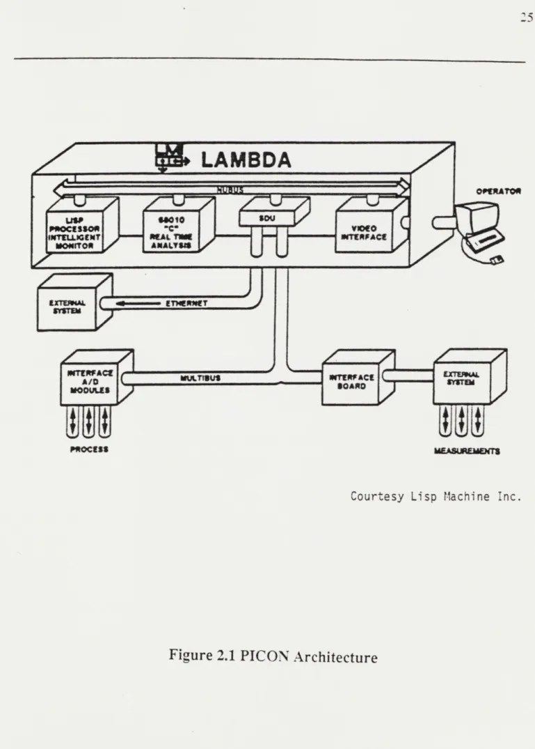
PICON combines artificial intelligence with a plant process computer to
enhance an operator's understanding of problems within the plant. PICON is intended for process control, although currently it is purely an operational aid for the plant operators. Hierarchically the device sits on top of an existing process control system (Fig. 2.1), and this control system is used as an input device for
PICON. PICON consists of a LISP processor for making inferences about the 20 F. Gibney, R. Pope, (editors), Catastrophe! When Man Loses Control. Bantam/Britannica Books, New
York, 1979.
LAMBDA
OIRT
MtLJI3US
IMAE EMEMTh
Courtesy Lisp Machine Inc.
Figure 2.1 PICON Architecture
x
A/D
eODU9Ss
usM esRUS
LISP WI mu? r~a
P=SSiOR owl" VON*
state of the plant, and a Motorola 68010 processor (in a UNIX/C environment) for collecting and preprocessing data. The key advances that PICON
represents are:
- It allows a description of the plant and its operating constraints (knowledge base) to be 'programmed' into the computer without the need to employ a skilled programmer.
- It is a real-time expert system.
- It can recognize accident scenarios as they unfold and recommend operator action while giving reasons for its recommendations.
- Its knowledge base can be easily updated and modified as the operators of the plant gain experience, thus enabling the system to learn with time.
Expert systems are fundamentally different than other computers in that there is a distinct difference between the knowledge in the program (knowledge base) and the program (inference engine) that acts upon that knowledge. In conventional programs, such as the Safety Parameter Display System
(backfitted to current Light Water Reactors), the knowledge is buried in the code (typically FORTRAN) and it takes an extensive effort to develop the code, and even a more dedicated effort to modify it. PICON's 'programming' is
accomplished by the engineer drawing a schematic on the screen, and then entering rules that describe the plant operators knowledge.
To draw the plant schematic the engineer chooses an icon from a menu and places it on the screen. Then attributes are described for this device (Fig. 2.2). The required attributes are a tag name, and for sensors, the engineering unit, and a currency interval. The currency interval is how long a value is valid.
If the currency interval is too long the value may not accurately represent the
variable at all times, and if it is too short the real time part (RTIME) of PICON will become overloaded.
PM3CDUPL.- TEPPEmR1 E-"RT -6EM$0R Ins tance
ttr1 AUt
-nAMW for sonmor: I rw
r0tia : Now
P1HUN: Choose 4 LMHM: 1LER-QUEUE: i PUM Y-6C- :
Figure 2.2 Establishing Attributes for Icons
Courtesy Lisp MIachine Inc
- /
--
K
I,'
I I I
bort
It this 06101g tas as*@
ngineering unit: F
urrgnc Interval (in secs.): Go
1l Ck Mere When Gone C,
-- -- --
-" 7
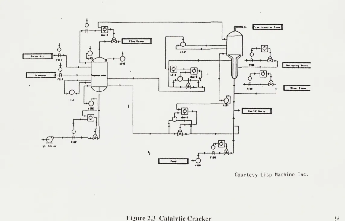
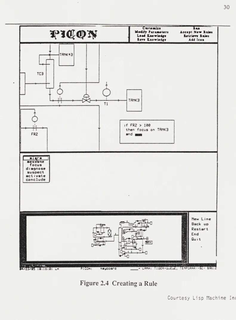
Once the schematic is complete (see Fig. 2.3 for a catalytic cracker schematic) the engineer enters the rules (Fig. 2.4). If the rules are carefully designed only the most important messages will be sent to the operator. This is
accomplished by creating primary and secondary rules. Primary rules are tested periodically and when one of them tests true it sends the operator a message and activates secondary rules which further diagnose the problem. For example the rule listed below activates secondary rules when the focus or suspect commands are used.
whenever regenerator-bed-temperature varies by 5 deg-f: if increase then request
"Regenerator temperature has risen 5 degrees." and focus on reactor
and focus on feed
and suspect possibility-of-afterbum if decrease then request
"Regenerator temperature has fallen 5 degrees." and suspect possible-behind-on-bum
and focus on regenerator22
This rule is translated from the above format into LISP by PICON. This capability removes the error prone task of translating the description of the plant
into the programming language while simultaneously preserving the 'knowledge' that the code represents for reference by future engineers.
The key advantage to a primary and secondary rule system is that it reduces the number of alarms which are sent to the operator, which allows the operator (and computer) to focus attention on the problem without being
distracted by further alarms. PICON is able to handle the thousands of process variables by allocating the data collection to RTIME.
01
owe
to-=
10,6% oil fill VOWI;j
LI-I L 1111 owefm
610,
Meow 11in1
Courtesy Lisp Machine Inc.
Figure 2.3 Catalytic Cracker 1 1.
U-4
0
U-0
V IA
TRMK43 TC3 TRNK3 TI i f FRZ > 1s0 then focus on TRNK3 FR2 and mes nme focus diasnose suspect act ivate canclude Mew Line Back up Restart End Quit
' - I h4:Fgr K .4om LAMA: CreTng R EM
Figure 2.4 Creating; a Rule
Multi-Module Control
RTIME provides the real time link between PICON and the process control system, and it accepts instructions from the inference engine part of
PICON. The inference engine tells RTIME how often data needs to be sampled,
and what preprocessing is necessary for the data (such as smoothing the data over time, or signal validation). In addition to these functions RTIME will notify the inference engine when a specified condition has been reached. RTIME takes into account the frequency with which the data is needed and accordingly queries the process computer for the data. PICON's processing speed is
capable of keeping all process variables current for a chemical plant, where typical sampling rates are on the order of a few seconds to hours. However, whether or not PICON's speed is sufficient for nuclear applications, where certain processes' time constants may be shorter, needs further investigation.
Since one of the features of advanced nuclear reactors such as the LMR and HTGR is inherent, passive safety, in part through designed-in slow response times, this situation may be less onerous than that for LWR applications.
The knowledge base is developed and tested on a plant simulator for an application as complex as an oil refinery or nuclear power plant. If
modifications are desired after PICON is installed at a plant, they would be first tested on a simulator before the PICON knowledge base is modified. PICON is currently (July 1985) being tested at a Texaco refinery in Texas with Texaco's simulator serving as the input device while the knowledge base is being fine-tuned. The successful use of a device such as PICON at an oil refinery will demonstrate that expert systems can be applied to industrial applications as complex and costly as a nuclear power plant.
2.3.2 Aerospace Applications
Airplanes and spacecraft, by necessity, employ digital computers for tasks such as navigation, engine control, and automatic guidance (auto-pilots). An aircraft such as a Boeing 747 cruising at 40,000 feet can not be manually flown with a straight and level attitude because the human eye can not sense small differences between the plane's attitude and the horizon. Automatic pilots were developed to both relieve the pilot from this tiring task and to increase the efficiency of long distance flying. Conversely, other tasks such as engine control and navigation were also delegated to digital computers for similar
reasons. Spacecraft represent an even more demanding application since the launching and guidance of rockets require extremely precise firing of their engines to achieve the required trajectory. The Space Shuttle is completely computer controlled through launch to landing with the pilot only taking over control of the craft in the final moments before landing. The Shuttle could even
land by computer control (as can the Boeing 747 and Lockheed L-1 011), but pilots and passengers prefer human control during this last part of the flight.
Computer control for aircraft has extended sensor fault detection and identification technologies, and experience in this field has helped increase the reliability of digital control systems. The consequences of failure are high in both economic and human terms. Insurance premiums for aircraft and injury liability are on the order of 800 million dollars for 1985, and 1358 people have died in commercial aircraft accidents from January 1 to August 16, 1985.23
Many of these crashes have been attributed to adverse weather conditions, such as the recent DC-10 crash in Dallas, Texas. Other crashes have been the result of multiple factors including weather and human error, such as that
Multi-Module Control
involving the two 747's which collided on the runway at Tenerife Island,
resulting in the death of 582 people. Of more relevance to control issues is the near fatal plunge of a 747 over the Pacific ocean in February of 1985.
A China Airline's 747 was cruising at 41,000 feet on autopilot when one
engine lost power. The autopilot remained engaged and the plane
subsequently plunged 32,000 feet in two minutes while rolling as far as 162 degrees to the right and nosing down 62 degrees. The incident appeared to be
both a combination of pilot error and auto-pilot malfunction.24 Experiences of
this sort need to be thoroughly studied and demonstrated to either be
in-applicable or of small probability before regulatory agencies will accept computer control in the nuclear field.
A more demanding application than an auto-pilot is an automatic landing
system. A microwave landing system was developed for a Boeing 737 that incorporates analytic redundancy and an Extended Kalman Filter (EKF).25 The
EKF unit computes estimates for aircraft position, velocity, altitude, horizontal winds, and normal operating sensor biases on the assumption of no sensor failures. This result is then compared to new measurements using multi-hypothesis testing, and if it is inconsistent the multiple multi-hypothesis test selects the most likely failure scenario and deletes the failed sensor making
appropriate changes in the no-fail filter and detectors. This application demonstrates the modeling of a system and, using equations of motion, it predicts the future state of the system. This method of sensor validation and
24, "NTSB Studies Reaction to Engine Loss in China Airlines Emergency Descent", Aviation Week & Space
Technolov., March 4, 1985. Page 29.
25 A.K. Caglayan, R.E. Lancraft, "An Aircraft Sensor Fault Tolerant System", NASA-CR-1 65876, Bolt,
Beranek and Newman, Inc., Cambridge, MA. April 1982.
control is being developed for boiling water reactor level determination.26 In the
extreme, this method could be used to develop a complete neutronic and thermodynamic model of the multi-module reactor system, which could then be
run in faster than real time to predict the future state of the power plant.
However, this would require a system such as a Cray-1 or possibly a parallel computer which has specialized processors for solving the neutronics and thermalhydraulics equations. Nevertheless, this type of system may help to
prevent unforeseen accident scenarios from endangering the system before the control system and operators can act.
The space shuttle Challenger experienced a control system failure on its
July 29, 1985 launch. A temperature sensor (one of two) in its number two main engine (one of three) failed off scale. The other redundant sensor showed a temperature of 1850'R two minutes later, which caused the flight computer to
shut the engine down. Emergency procedures were employed to get the shuttle into a safe orbit and to prevent the 39 ton external fuel tank from falling on
Europe or the Middle East. As the remaining two engines continued firing the number three engine temperature sensor A failed and the other sensor began rising similarly to the previous fault in the number two engine. At this point the crew was instructed to inhibit the computer from shutting down the engine since the sensors were suspected of indicating false readings. This incident
demonstrates the necessity of allowing the operators to override the computer. Since the shuttle launch requires faster than human action, the computer must be employed and allowed to act without pre-approval for every step. However, in nuclear power plants the time domain is much longer, and a more
appropriate method would be to require the operator to verify the plant status in
26 G. M. Garner, "Fault Detection and Level Validation in Boiling Water Reactors," PhD Thesis, Charles
Multi-Module Control
various stages of operation before the computer is allowed to proceed with the next step.
The aerospace community has developed control systems that allow complete control of the aircraft by a relatively few number of people, while ensuring the safety of both the craft and its passengers. The techniques developed for sensor fault detection and isolation are directly applicable to
nuclear power plants, and further developments for complex systems such as the space station promise to advance control technologies further.
2.4 Chapter Summary
Control technology both in and outside the nuclear industry has
employed digital computers extensively. The chemical process control industry is making the most use of artificial intelligence techniques for control while the aerospace industry has made extensive use of sensor fault detection
techniques. Canada and Japan both use digital computers for direct control of a nuclear power plant, and are advancing the technology of digital power plant control. One of the key applications of computer control is in chemical process plants, because of their many similarities to nuclear power plants, and because the large financial capabilities of the chemical industry promise to advance artificial intelligence techniques in process control considerably.
The joining of these advances with the latest techniques in fault tolerant computers, display and instrumentation technologies, and human factors
engineering, will provide a sophisticated and reliable control system for a multi-module nuclear power plant.
Multi-Module Control
Chapter 3
Review of New Technology
3.1 Introduction
Electronic and computer technologies are advancing at an ever
increasing pace. In the field of personal computers, a machine introduced three years ago is outdated. Control technology is advancing similarly, as is
demonstrated by three areas: computer networking, fault tolerant processing, and information display technology. Additionally, human factors engineers
have begun to apply their expertise to the unique world of digital plant control, which is maximizing the use of the new technolgy to the utmost.
The use of many personal computers in one office complex has pressed the computer industry to network their machines together for office automation. On a larger scale, minicomputers in different buildings of a city are being
networked via fiber optics for large, high speed data transfer. This technology is directly applicable to nuclear power plant control.
The defense, banking, and aerospace industries have motivated the computer industry to develop fault tolerant computers for their needs, which
require the computer to have unavailability rates expressed in minutes per year. This type of computer is particularly well suited to power plant control.
Addtionally, in the aerospace field, engineers have developed a variety of algorithms to analyze raw data for validity.
Finally, human factors engineers have made numerous studies as to which colors are best suited for different applications, the pros and cons of
various presentation schemes, and a host of parameters that impact an operator's efficiency.
The following sections give an introduction to all of these complex areas; more thorough explanations can be found in the references.
Multi-Module Control
3.2.1 Data Communication and Analysis
Data Communication - Computer Networking:
There are many different methods of networking computers. These include simple low speed systems for personal computers, to high speed fiber optics. All of them, except fiber optics, are limited to a maximum transmission rate of 50 megabits per second, and are susceptible to electromagnetic
interference (EMI). Rates of 50 megabits per second (Mbits/sec) are probably sufficient for power plant control, however immunity from EMI is required for
nuclear power plant control applications. Thus, fiber optics is the medium of choice for a nuclear power plant. The only deficiency that fiber optics has is that its transmission clarity deteriorates in a high radiation environment. The
American National Standards Institute is currently (February 1985) defining a standard for fiber optic networks called the Fiber Distributed Data Interface
(FDDI).27
FDDI is a ring topology LAN (Local Area Network) designed for communication at rates up to 100 Mbits/sec over a distance of one to two kilometers. This is based on current fiber optics technology which is not as mature as other communication techniques. Fiber optics, when fully mature, will be capable of transmitting at a sustained rate of 80 Mbits/sec between 1000
nodes over a 200 kilometer path.28
27 N. Makhoff, "LANs Team Up to widen the Network Connection," Comouter Design. Vol. 24, No. 2,
(February, 1985). Page 108.
28 lbid 27
Data Analysis:
Several techniques have been developed to perform validation and verification of sensor data in control systems. They include voting, generalized
likelihood ratio (GLR), multiple hypothesis, extended Kalman filter, the
sequential probability ratio test (SPRT), and multifilter methods among others.
All have their specific advantages and disadvantages, and are best suited to a
particular application. A detailed explanation of each method is beyond the scope of this paper (see A.S. Willsky's survey for more information).29
Voting, the simplest method, is best applied when numerous identical sensors are available. Identical sensors have the same uncertainty and bias, and thus the data can be directly compared with the majority determining the true value. If the sensors were unlike, or if additional data was analytically generated, then a simple voting scheme can not be used because unlike data (different uncertainties, etc.) can not be directly compared. Thus, problems arise when the sensors are slightly different or when their values are a function of position, such as core power meters that measure the gamma ray flux. The other methods of determining sensor faults are variations of voting which try to improve the certainty of the result. Each of them will probably be used in various subsystems in the multi-module plant. For example, a fault detection and level validation method developed for BWRs considers the use of an
extended Kalman filter or a nonlinear observer, for interpretation of the core liquid coolant level.30 The data in a complex control system would usually be analyzed by in a digital computer, rather than in a hardwired logic system.
29 A.S. Willsky, "A Survey of Design Methods for Failure Detection in Dynamic Systems", Automatica. Vol.
12, pp. 601-661. Pergamon Press, Great Britain. 1976.
30 G. M. Garner, "Fault Detection and Level validation in Boiling Water Reactors," PhD Thesis, Charles
Multi-Module Control
3.2.2 Fault Tolerant Computers
A computer system that must be available continuously for the economic
operation of a given process requires fault tolerance. Typical users of fault tolerant computers are airline reservation systems, and control systems for aircraft/spacecraft. There are many different techniques which can give a computer varying degrees of hardware fault tolerance. Hardware fault
tolerance is different than sensor fault tolerance in that hardware faults occur within the computer, whereas sensor faults are external to the computer.
Fault detection techniques are of (roughly) two types. The first uses software to detect faults. This has been used since computers were first built, and is used to some degree on almost all computers. For example, in data communications, a parity bit is added to each byte that indicates whether the sum of all the bits in the byte are odd or even. If, at some point, the parity bit does not match its byte then an error has occured. Steps can then be taken to correct the byte, such as retransmission. Other more complex software
techniques are "double checking", "check summing", "check-pointing", watchdog timers, and numerous others.31 The second type of fault detection involves the use of hardware. This usually involves the replication of key components of the system for use as a backup or a check. When a checking method is used, the additional component is processing the same task and the
results are compared to check for errors. This is known as self checking and is used only in systems that have at least three components processing the same task. Dual redundancy is used when the backup method is chosen.
31 W. N. Toy, M. Morganti, "Fault Tolerant Computing," Computer. Vol. 17, No. 8, (August 1984). Page 6.
"Dual redundancy is the most common (hardware implemented) fault tolerance scheme."32 A second computer system is in a'hot standby' mode,
and when the primary computer fails, the second computer takes over. This increases the availability of the computer substantially. A major disadvantage is that the control system is unavailable while control is being switched from the primary computer to the back-up computer. After the switchover any lost
messages must be retransmitted and any corrupted data must be corrected.33 This difficulty makes dual redundancy less than desirable for nuclear power
plant control.
Triple modular redundancy avoids any momentary lapse of control due to a single error. In this method, the control computer and all its subsystems are triplicated. Each system is processing all signals and they periodically vote on the output. If one of the computers disagrees, its result is eliminated and the correct control output is still applied. "System availability with this approach is extremely close to 100 percent."34 The disadvantage with this approach, as well as with dual redundancy, is that the software must be imbedded with routines to check when a failure in the hardware occurs (e.g. a vote occurs on the output to determine if one of the triad has failed). This unnecessarily complicates the development of software, and this could severely hamper the development of the complex operating routines necessary for complete control of a multi-module nuclear power plant. A solution to this is a method used by Stratus Computer* which is totally hardware dependent, and thus frees the software engineer from fault tolerance considerations.
32 J. H. Wensley, "Redundant Modules May be Best for Control Systems," Computer Design Vol. 24, No. 4,
(April 1985). Page 121.
33 lbid 27
34 lbid 27, Page 122
Multi-Module Control
Stratus Computer uses a technique called 'pair and spare', a subset of the 'self-checking' method. It is simple in concept and is illustrated in Figure
3.1.
Figure 3.1
Pair and Spare Strategy
The CPU board is shown. The CPU in a real system may actually reside on multiple boards, but the concept is still the same. As shown, the CPU is replicated four times, with CPUs Al and A2 residing on a single board and CPUs B1 and B2 residing on the other, single, board. All four CPUs are executing the same task simultaneously and are sending the results onto the system bus (not shown). Before the results are put on the bus, they are first checked in the comparator (white rectangle) shown in the middle of each board.
If there is a fault in CPU A2, it will not match the result from the correctly
functioning CPU Al. The comparator prevents the error from entering the system bus. Since CPUs B1 and B2 are still functioning correctly, the system continues its operation without any degradation. Meanwhile, the faulty board
43 CPU R211
--_Me
Co Emparator....
...
CPUR2I *1'
*
...
ICPU
B11I
....
El=
CompiaturP EM1IMEM
FT-notifies the modem in the system that it has failed. The modem dials Stratus Computer's support center and a replacement board is sent to the customer via overnight delivery. The first time the customer realizes that something is wrong is when the new board arrives. The customer simply slides out the faulty board (the one with the flashing red light), and inserts the new one (while the system is running).
Only the CPU and memory boards use the 'pair and spare' approach, the rest of the system uses other self-checking techniques. This approach has proven quite successful in the marketplace, as Stratus' 1983 revenues were
$20 million, its second year on the market.36
An important new fault tolerant design, that is bringing together fiber optics, fault tolerant computers, and sensor fault tolerance techniques is a generic distributed processing system being developed by the Charles Stark Draper Laboratory. CSDL's system is called AlPS - Advanced Information
Processing System (shown in Figure 3.2; not shown on the diagram is a simple
processor off one of the nodes).37 It is a generic design intended for use on
NASA vehicles. AlPS uses a fault tolerant processor (FTP) for critical control
functions, with the degree of fault tolerance depending on the criticality of the function, i.e. a duplex FTP might be used for communications, whereas a triplex FTP might be used for life support system control . AIPS uses a central
controller for supervisory control and distributed controllers for local intelligent control. Each card in the central controller is triply redundant, and the errors are detected by voting on the results of each calculation. If one card disagrees with
36 0. Serlin, "Fault-Tolerant Systems in Commercial Applications," Computer Vol. 17, No. 8, (August
1984). Page 24.
37 The information on AIPS was supplied by Dr. John Hopps, Charles Stark Draper Laboratory in July,
Multi-Module Control
the others, it is dropped out of the system and an online spare is picked up automatically to complete the triad. Additionally, each node in the network is triplicated for fault tolerance, and the communication medium between nodes will eventually be fiber optic. The latest design of AIPS (Fall, 1985) uses quadrex redundancy in both the central controller, and in the communication medium. AIPS represents the latest in distributed control systems, as it includes fault tolerance in all of its functions.
Figure 3.2
AIPS Proof-Of-Concept Configuration
Multi Processor + I/0
(3 Triads) - Network I/0- Triplex Intercomputer Network ( Gatew it ) V AX 10 Duplex 11/780 1/0 -FTP
CSDL - used with pemisn
3.2.3 Information Display Technology
A digital control system for a nuclear plant requires a special blend of
display qualities that is only beginning to be met by new information display devices. The display qualities desired include: high resolution, color, implosion resistance, flicker free operation, and high luminance.
High resolution and color are needed because diagnosing a problem in a dynamic and complex system requires that the operators be able to discern the information quickly and accurately. Implosion resistance is required since earthquakes are considered in the design of a nuclear plant. Earthquakes can cause cathode ray tubes (CRTs) to implode, endangering the safety of both the plant and operators; however properly mounted CRTs are considered rugged enough to meet earthquake design requirements. Finally, flicker free displays with a high luminance prevent the operators eyes from tiring when looking at the display for long periods of time.
Current CRTs are able to provide high resolution and luminance, color, and relatively flickerless displays. However, CRTs are susceptible to implosion and are fairly bulky. In contrast, new flat panel displays overcome both of these difficulties.
There are four different types of flat panel displays; Liquid Crystal Display
(LCD), Gas Electron Phosphor (GEP), plasma, and electroluminescent (EL).
LCDs are commonly used in watches, calculators and portable computers, while the others are used only in larger, more expensive systems (except that Grid System's portable computer uses a plasma display, but it is quite