Publisher’s version / Version de l'éditeur:
Journal of the Acoustical Society of America, 36, 11, pp. 2171-2174, 1965-03-01
READ THESE TERMS AND CONDITIONS CAREFULLY BEFORE USING THIS WEBSITE.
https://nrc-publications.canada.ca/eng/copyright
Vous avez des questions? Nous pouvons vous aider. Pour communiquer directement avec un auteur, consultez la première page de la revue dans laquelle son article a été publié afin de trouver ses coordonnées. Si vous n’arrivez pas à les repérer, communiquez avec nous à PublicationsArchive-ArchivesPublications@nrc-cnrc.gc.ca.
Questions? Contact the NRC Publications Archive team at
PublicationsArchive-ArchivesPublications@nrc-cnrc.gc.ca. If you wish to email the authors directly, please see the first page of the publication for their contact information.
NRC Publications Archive
Archives des publications du CNRC
This publication could be one of several versions: author’s original, accepted manuscript or the publisher’s version. / La version de cette publication peut être l’une des suivantes : la version prépublication de l’auteur, la version acceptée du manuscrit ou la version de l’éditeur.
For the publisher’s version, please access the DOI link below./ Pour consulter la version de l’éditeur, utilisez le lien DOI ci-dessous.
https://doi.org/10.1121/1.1919339
Access and use of this website and the material on it are subject to the Terms and Conditions set forth at
Comparison of reverberation-room and impedance-tube absorption
measurements
Olynyk, D.; Northwood, T. D.
https://publications-cnrc.canada.ca/fra/droits
L’accès à ce site Web et l’utilisation de son contenu sont assujettis aux conditions présentées dans le site LISEZ CES CONDITIONS ATTENTIVEMENT AVANT D’UTILISER CE SITE WEB.
NRC Publications Record / Notice d'Archives des publications de CNRC:
https://nrc-publications.canada.ca/eng/view/object/?id=69a7dad0-7e44-4bf7-8d59-e3d15b511d32 https://publications-cnrc.canada.ca/fra/voir/objet/?id=69a7dad0-7e44-4bf7-8d59-e3d15b511d32
impliqug le calcul
rgsultats particuli'erement intgressants ibration du diaphragme du matgriau 1
Reprinted from THE JOURNAL OF THE ACOUSTICAL SOCIETY OF AMERICA, Vo1. 36, No. 11, 2171-2174, November 1964
Copyright, 1964 by the Acoustical Society of America.
Printed in U. S. A.
Comparison of Reverberation-Room and Impedance-Tube
Absorption Measurements*
Divisiorz of Bz~ilditzg Researcl~, iVational Researclz Coz~ncil, Oltawa, Otztario, C a ~ ~ a d a
(Received 9 June 1964)
Reverberation-room absorption measurements on some 50 samples of commercial acoustical materials were compared with values predicted from impedance-tube measurements on the same materials. The predictions involved calculating the random-incidence absorption for the standard 9 x 8 - f t patch of material. At fre- quencies of 125, 250, 500, 1000, and 2000 cps, various degrees of correlation mere found between impedance- tube data and reverberation-room results involving mountings 1, 2, and 4 (adhesive, furring strips, and rigid backing, respectively). Of special interest were results at 250 cps in which the absorption was sensitive to type of mounting. For mountings that permitted diaphragm vibration of the material, the reverberation-room re- sults were substantially higher than predicted values based on rigidly backed samples. Remnants of this be- havior appeared at 500 cps for the thin materials, but otherwise correlation was good at this and higher fre- quencies. Highly absorptive materials correlated better than those with low absorption, for which reverbera- tion-room results still tended to be somewhat higher than mas predicted.
I
N the Anzerican Slalrdard Acouslical Ter?ni~zology, the faces. Various relations have been derived, of which sound-absorption coefficient of a surface is defined the most importailt are the Sabine and Norris-Eyring as the fraction of incident sound energy absorbed or formulas. For reverberation rooms where the average otherwise not reflected from the surface. Uilless other- absorption coefficient of the surfaces is always less than wise stated, a diffuse sound field is assumed. Although 0.10, the two formulas become substantially the same, this definition is clear and concise. it leaves unresolved and the s i m ~ l e r Sabine formula is customarilv used. the question of how to measure the sound-absorption The key hypothesis in reverberation theory is that the coefficient. It is the object of this study to compare the souild field is diffuse and that the room surface is results of two quite different methods of measuremeilt therefore exposed to an assembly of waves from all employing the reverberation room and the impedance angles of incidence.tube. Several similar studies have been made since the Briefly, the testing procedure4 is to measure the impedance tube was first developed, but generally they reverberation time in an empty reverberant room and involved only a few isolated comparisons and led to no then repeat the process after introducing a sample of consensus regarding the degree of correspondence be- the test material. From the two reverberation times, the tween m e t l ~ o d s . ~ - ~ ~ The chief feature of the present work total absorptions in the two cases are determined, the is that a large number of test specimeils and test con- difference being attributed to the absorption added by ditions have been examined. the sample. Dividing the sample absorption by sample The reverberation-room method requires a knowledge area gives the absorptioil per square foot, which is of the relation between the reverberation time in a taken to be the absorption coefficient.
room and the total sound absorption of the room sur- The assumption that the absor~tion due to a surface *This paper is a contribution from the of Uuilcling is simply the product of its area and absorption coefi- Research, National Research Council, Canada, and is p~lblishecl ciellt is valid ollly when the dimensions of the surface with the approval of the Director of the Division. are large as conlpared to a wavelength. The standard
F. G. Tyzzer and H. A. Leedy, J. Acoust. Soc. Am. 26,651-656
(1954'). reverberation method employs a 9x8-ft specimen.
ZP.'M. Morse and R. H. Bolt, Rev. Mod. Phys. 16, 69-150
(1944) ; see p. 141. "Tentative Method of Test for Sound Absorption of Aco~istical 3L. L. Beranek, Acoltstical hfeas~lrertretzls (John Wiley & Sons, Material in Reverberation Rooms," Am. Soc. Testing Mater. Inc., New lrork, 1949), p. 861. ilSTAl 423-60 T (1960).
2172 O L Y N Y K A N D N O R T H W O O D
FIG. 1. Mounting condi-
Nail tions selected for- study.
Slripr at lT, (Designations follow prac-
tice of Acoustical Materials
-
MOUNTING 4When a patch of absorbing material as small as this forms part of a highly reflecting plane surface, it absorbs extra energy because of diffraction near the edges. Thus, dividing sample absorption by sample area may be expected to give coefficients higher than the infinite-area values. With very efficient absorbers, the effective coefficient obtained with a standard test area can quite legitimately exceed unity. This is demon- strated in some instances in the present study. A11 obvious way to reduce the importance of this factor
would be to use a much larger sample area, but then it
becomes dficult to maintain the required diffuse sound field in the room.
Another point to observe is that the absorption of most acoustical materials depends on the method of mounting them. The Acoustical Materials Association has established a set of standard test mountings, of which three were selected for the present study.
The impedance-tube method is based on a measure-
L E G E N D
G e s s M o u n t i n g
21.2
1 2 4
I
R E V C R B C R A T I O N - R O O l r l C O E F F I C I E N T
FIG. 2. Calculated and observed values of absorptioil coefiicient a t 2000 cps.
ment of the normal-incidence acoustic i~npedance.~ With
suitable equipment, the n1easurement is simple and fairly precise. If the material is "locally reacting" (i.e., if there is little propagation of souild laterally within the material), it is then possible to calculate the random- incidence absorption coefficient for an infinite area of the material. It is also possible to calculate the effective coefficient for a small patch of material such as that tested in the reverberation room.G As the tube method is necessarily a small-scale one (usually the specimeils are 2-3 in. in diameter), the effect of typical large- scale mountings cannot be simulated in the tube.
The present comparisoil is based on an assortment of some 50 commercial materials on which both kinds of measurements had been made. Most of the materials
were in the form of acoustic tiles 1 ft square, but a few
0 I x I I I I
0.2 0.4 0.6 0.8 1.0 1.2 1.4 R E V E R B E R A T I O N - R O O M C O E F F I C I E N T
FIG. 3. Calculated and observed values of absorptioil coefficient at 1000 cps.
other types such as sprayed-on materials are included as well. From the tube results, calculations were made of the effective coefficients for the standard sample area used in the reverberation room. These measuremeilts were made on a routine basis over a period of about 6 years.
I. EXPERIMENTAL DETAILS
The reverberation room used for these tests is 26X21X16 f t high, giving a total volume of 8880 cu f t (252 m3). Diffusion is provided by a 6 x 8 - f t vane "Method of Test for Impedance and Absorption of rlcoustical Materials by the Tube Method," Am. Soc. Testing Mater. ASTM 384-58 (1958).
"T. D. Northwood, J. Acoust. Soc. Am. 35, 1173-1177 (1963).
(More-complete information is given in Building Note 44, Divisioil of Building Research, Natioilal Research Council, Ottawa, Canada.)
R E V E R B E R A T I O N - R O O M A N D T U B E A B S O R P T I O N 2173
inclined a t 30 deg from the vertical and rotating a t 5 rpm. Warbled sound is produced by four loudspeakers at four corners of the room and picked up by four micro- phones a t the other corners. The standard 8x9-ft test specimen is placed on the floor approximately 5 ft from the nearest walls. The reverberation times of the empty room range from 2.6 sec a t 4000 cps to 8.9 sec a t 125 cps. Figure 1 gives details of the three sample mountings used in the reverberation-room tests. Mounting 1 in- volves cementing the sample to a hard backing with four cement patches of about 2 in. in diameter by
in. thick. I11 mounting 2, the sample is nailed to
nominal 1x3-in. furring strips. I n mounting 4, the
sample is laid directly on the laboratory floor.
The impedance tube employed is 22 in. i.d. by about 3 ft in length. Sound from a horn driver unit is intro-
L E G E N D 3 1 . 2 C T h i c k n e s s M o u n t i n g 1 2 4 (L I A s s o r t e d P:
FIG. 4. Calculated and observed values of absorption a t 125 cps.
duced a t one end through an annular ring located so as to avoid excitation of the first radial mode. The probe
microphone consists of a small piezoelectric trans-
ducer mounted on the end of a *-in.-diam tube, which is moved along the axis of the impedance tube to explore the interference pattern resulting from incident and reflected sound waves. The upper frequency limit of the tube, dictated by its diameter, is about 3200 cps, so that the highest of the standard frequencies that can be studied is 2000 cps. Associated equipment includes a beat-frequency oscillator whose frequency is monitored by an electronic counter and a narrow-band inicrophone amplifier. All tube samples were tested wit11 a rigid backing comparable to ulounting No. 4 in the rever- beration room. L E G E N D
-
-
- 0 0.2 0.4 0.6 0.8 1.0 1.2 1.4 R E V E R B E R A T I O N - R O O M C O E F F I C I E N TFIG. 5. Calculated and observed values of absorption coefficient a t 250 cps for all except $-in. tiles.
11. FSSULTS
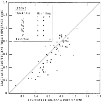
Figures 2 to 7 show all the results as a function of
material thickness, mounting, and frequency. It may
be seen that on the average the correlation is good a t 2000 and 1000 cps (Figs. 2 and 3), even through there is considerable scatter in individual results. This scatter
is attributable to three main causes : the different mount-
ing conditions for tube and reverberation-room tests,
0.2 0.4 0.6 0.8 1.0 1.2 1.4 R E V E R B E R A T I O N - R O O M C O E F F I C I E N T
FIG. 6. Calculated and observed values of absorption coeaicient a t 250 cps for ;-in. tiles.
2174 O L Y N Y I C A N D N O R T H W O O D
R E V E R B E R A T I O N - R O O M C O E F F I C I E N T
I:IG. 7. Calculated and observed values of absorption coefficient FIG. 8. Diaphragm absorption as a function of mounting and
a t 500 cps. frequency for two typical samples.
departures of materials from the locally reacting as- sumption, and lack of precision in the test methods.
Mountings 1 and 2, which involve an air space be- hind the material, permit diaphragm vibrations of the material. Materials with low flow resistance also in- volve the air space since it combines with the flow resistance to form a resonant absorption system. A similar effect occurs when sound can penetrate through cracks between tile elements. All these effects give rise to an additional amount of absorption in reverberation- room tests in addition to that provided by the material proper. The extra absorption caused by the mounting is most evident when the intrinsic absorption of the material is low. The effect is evident in the lower por-
tions of Figs. 2 and 3, and is increasingly important as
the frequency decreases, both because mounting ab- sorption is higher in this range and because the material absorption is generally lower. At 125 cps, where the material absorption is very low, there is almost no correlation between calculated and reverberation-room absorption.
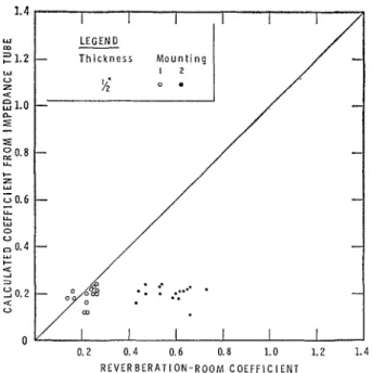
The most interesting effects of the mounting system are at 250 and 500 cps (Figs. 5-8). Mounting No. 2,
in which tiles are edge-mounted over a space, shows a
large extra absorption a t 250 cps. A similar effect is evident a t 500 cps for mounting No. 1, in which the tile supports are closer together and the back space is smaller. I n a few cases, tiles were tested on both mount- ings, with results as illustrated in Fig. 8. The effects of
the two mountings are clearly shown for two typical samples.
The locally reacting assumption is a reasonable one for materials of high flow resistance, but results for a few of the materials tested may be suspect on this account. The nature of the resulting discrepancy is difficult to predict because of the involvement of the back space, but the most probable effect is to reduce slightly the reverberation-room value relative to the value predicted from the impedance tube.
Finally, the precision of the measuring procedures may be considered. The impedance-tube method is generally very precise; the chief source of possible error is sampling, in the case of nonuniform materials. On the other hand, the discrepancies among measurements from different reverberation rooms are well known.'.h7 Even in the one laboratory where these tests were done, it was found that the results obtained with a very small specimen were dependent on the position of the speci- men. Limited experiments indicate that increased dif- fusion in the room reduces the variation with sample position and also improves the correlation with imped- ance-tube calculations.
I t is concluded that, apart from effects attributable to mounting conditions, the absorption coefficients measured in the reverberation room are generally con- sistent with the values calculated from the acoustic impedance of the materials.