HAL Id: hal-00110524
https://hal.archives-ouvertes.fr/hal-00110524v2
Submitted on 18 Dec 2006
HAL is a multi-disciplinary open access
archive for the deposit and dissemination of
sci-entific research documents, whether they are
pub-lished or not. The documents may come from
teaching and research institutions in France or
abroad, or from public or private research centers.
L’archive ouverte pluridisciplinaire HAL, est
destinée au dépôt et à la diffusion de documents
scientifiques de niveau recherche, publiés ou non,
émanant des établissements d’enseignement et de
recherche français ou étrangers, des laboratoires
publics ou privés.
Nucleation of magnetisation reversal, from nanoparticles
to bulk materials
Jan Vogel, Jérôme Moritz, Olivier Fruchart
To cite this version:
Jan Vogel, Jérôme Moritz, Olivier Fruchart. Nucleation of magnetisation reversal, from
nanopar-ticles to bulk materials.
Comptes Rendus Physique, Centre Mersenne, 2006, 7, pp.977.
hal-00110524, version 2 - 18 Dec 2006
Nucleation of magnetisation reversal, from nanoparticles to bulk
materials
Jan Vogel
a, J´
erˆ
ome Moritz
b, Olivier Fruchart
aa
Institut N´eel, CNRS, 25 rue des Martyrs, B.P.166, F-38042 Grenoble Cedex 9, France
b
SPINTEC (URA 2512 CNRS/CEA), CEA/Grenoble, 17 Rue des Martyrs, F-38054 Grenoble Cedex 9, France
Abstract
We review models for the nucleation of magnetisation reversal, i.e. the formation of a region of reversed mag-netisation in an initially magnetically saturated system. For small particles models for collective reversal, either uniform (Stoner-Wohlfarth model) or non-uniform like curling, provide good agreement between theory and ex-periment. For microscopic objects and thin films, we consider two models, uniform (Stoner-Wohlfarth) reversal inside a nucleation volume and a droplet model, where the free energy of an inverse bubble is calculated taking into account volume energy (Zeeman energy) and surface tension (domain wall energy). In macroscopic systems, inhomogeneities in magnetic properties cause a distribution of energy barriers for nucleation, which strongly influ-ences effects of temperature and applied field on magnetisation reversal. For these systems, macroscopic material parameters like exchange interaction, spontaneous magnetisation and magnetic anisotropy can give an indication of the magnetic coercivity, but exact values for nucleation fields are in general hard to predict.
To cite this article: J. Vogel, J. Moritz, O. Fruchart, C. R. Physique 7, 977 (2006). R´esum´e
Nucl´eation du renversement de l’aimantation, de nanoparticules aux syst`emes macroscopiques. Nous passons en revue diff´erents mod`eles traitant de la nucl´eation dans des syst`emes magn´etiques. La nucl´eation est l’´etape qui initie le renversement de l’aimantation dans des objets magn´etiques pr´ealablement satur´es en champ. Pour des particules d’extension spatiale r´eduite -typiquement inf´erieure `a la largeur de paroi de domaines magn´etiques- les mod`eles de renversement collectif, homog`ene (mod`ele de Stoner-Wohlfarth) ou par exemple de type ’curling’ donnent un bon accord avec l’exp´erience. Pour des objets microscopiques et des couches minces, nous discutons deux approches, l’une supposant le renversement homog`ene de l’aimantation dans un volume d’activation de taille r´eduite, l’autre fond´ee sur l’´energie de formation d’une gouttelette. Cette derni`ere est calcul´ee en tenant compte de l’´energie de volume (terme Zeeman) et de surface (´energie de paroi). Les deux approches sont utilis´ees pour d´eterminer des volumes d’activation ou ajuster des courbes exp´erimentales. Il semblerait que le mod`ele de gouttelette soit plus pertinent pour expliquer les variations thermiques des champs de renversement ou leur comportement dynamique. Dans les syst`emes macroscopiques, les inhomog´en´eit´es du mat´eriau donnent lieu `a des distributions d’´energie de barri`ere qu’il est n´ecessaire d’int´egrer dans les calculs. Ainsi les param`etres comme l’anisotropie ou l’´echange peuvent donner une indication de la coercitivit´e, mais il est en g´en´eral difficile de pr´evoir sa valeur exacte.
Pour citer cet article : J. Vogel, J. Moritz, O. Fruchart, C. R. Physique 7, 977 (2006).
Key words: nucleation ; magnetisation reversal ; magnetic thin films ; thermal activation
1. Introduction
The spontaneous or magnetic field-induced reversal of the magnetisation direction in materials and nanostruc-tures has been the subject of intensive studies since many decades. The use of magnetic materials in applications ranging from compass needles to electrical motors, truck brakes, cellular phones and personal computers has triggered the search for materials with particular properties concerning both their static and dynamic behaviour. Materials used e.g. in transformers need to switch their magnetisation direction under very small values of applied magnetic fields to minimise losses; these are so-called soft magnetic materials. On the other hand, permanent magnets used in electrical motors and generators need their magnetisation to be as stable as possible against both magnetic fields and thermal effects; these are so-called hard magnetic materials. Consider however information written on magnetic storage media in the form of small magnetic grains. In this case, a compromise must be found for the grains need to be stable for years, but on the other hand their magnetisation direction should respond quickly to moderate magnetic field values to allow information to be written fast. Thus for each particular case an understanding of how magnetisation reversal proceeds is needed. Magnetisation reversal can take place in different ways, depending on the size of the object and physical parameters like the exchange interaction and magnetic anisotropy. In the atomic case, a magnetic field along a direction other than the initial magnetisation will cause a torque on the magnetisation given by M × Hef f, where Hef fis the local effective field. This torque will induce a
precessional motion of the magnetisation around the effective field. In materials, damping will occur and eventu-ally the magnetisation will align with the effective field. This scheme is described by the Landau-Lifshitz-Gilbert (LLG) equation [1] of precession and damping. This equation remains valid also for very small particles, i.e. when the magnetic moments of the different atoms are strongly coupled one to another by exchange interaction and act like a so-called macro-spin. This simple reversal scheme is referred to as coherent or uniform magnetisation reversal.
In nearly all materials the rotational symmetry is lost as a consequence of the discrete crystalline structure and the spin-orbit coupling, or due to dipolar interactions. This effect is called magnetic anisotropy, which can be expressed as an angular-dependent energy. In the presence of anisotropy, a field of finite size is needed to reverse the magnetisation. For uniaxial anisotropy the angular dependence of the uniform reversal has been derived by Stoner and Wohlfarth [2] (SW). These features are treated in Section 2. For micrometer-sized particles or dots the macrospin approximation is not exact anymore and local deviations from uniform magnetisation usually exist. Interestingly, notice that precession-like magnetisation reversal may still take place at the micrometer scale [3], but in that case the non-uniform magnetisation has to be taken into account for an accurate description of the magnetisation reversal [4]. This is discussed in Section 3.
For macroscopic films (Sec. 4) and bulk magnetic materials (Sec. sec-bulk), magnetisation reversal usually starts at magnetic fields that are significantly lower than expected from the theory of uniform reversal of the entire system; This is the so-called Brown’s paradox [5]). Rather, in these systems magnetisation reversal takes place through a process of nucleation of small reversed domains (usually on inhomogeneities or defects) and a subsequent propagation of magnetic domain walls. Here we will treat nucleation processes only. The propagation of domain walls, once a stable nucleation center is formed, is not discussed. Over the years, different models have been developed to take into account the role of nucleation in non-uniform magnetisation reversal and to explain experimentally obtained values of reversal fields and other dynamic properties of magnetic materials and films. These basic models will be reviewed in this paper, for small particles and dots as well as for magnetic thin films. This overview will be non-exhaustive, and given from an experimentalist point of view. In some cases, a comparison with experimentally obtained results will be made. The role of inhomogeneities in the samples themselves (like defects and finite-size effects) on the nucleation of reversed domains will be discussed. In the following sections magnetisation reversal and nucleation is considered in systems of increasing dimensionality and thus complexity, from zero-dimensional to three-dimensional, i.e. bulk.
2. Uniform or ’coherent’ reversal
For very small particles, the exchange interaction is dominating and induces uniform magnetisation. The upper critical size for uniform magnetisation depends on the detailed shape of the particle and on the material parameters
Email addresses: jan.vogel@grenoble.cnrs.fr (Jan Vogel), jerome.moritz@cea.fr (J´erˆome Moritz), olivier.fruchart@grenoble.cnrs.fr(Olivier Fruchart).
[6,7,8]. For particles smaller than this critical size, magnetisation reversal will be uniform and nucleation processes as defined above can not take place. Even though uniform magnetisation reversal is not the subject of this paper, it is briefly mentioned here since uniform reversal is also the base of models for nucleation of reversed domains in macroscopic materials. In that case, a so-called activation volume is considered, in which the magnetisation is assumed to reverse coherently, and the energy for this reversal may be calculated assuming an independent volume or taking into account the interaction of the reversed volume with the matrix.
The energy of a uniformly magnetised particle of volume V in an external magnetic field H depends on the spontaneous magnetisation MS and on the orientation r of the magnetisation with respect to the external field
and with respect to the anisotropy axes of the particle [9]:
E(r, H) = EK(r) − µ0MSV r • H (1)
where EK(r) is the energy caused by the magnetic anisotropy of the particle and the second term is the Zeeman
energy. Stoner and Wohlfarth [2] considered the simple case of magnetisation reversal in a single domain particle with uniaxial magnetic anisotropy and a positive anisotropy constant K. In that case, EK(r) = - KVcos2θ, where
θ is the angle between the direction of magnetisation and the easy axis. A two-dimensional plot of the switching field as a function of θ results in the well-known Stoner-Wohlfarth astroid [10]. The SW model was later extended to macro-spin particles with an arbitrary three-dimensional anisotropy by Thiaville [11], with an experimental demonstration given by Bonet et al. [9]. In all these models, the angular dependence of the reversal field of the particle is derived by calculating the field for which the energy barrier ∆E(H) that has to be overcome to reach the minimum energy state vanishes. This means that thermal effects that may help to overcome this barrier are not taken into account. Thermally-assisted reversal has first been considered by N´eel [12] and Brown [13]. In the so-called N´eel-Brown model, the probability that the magnetisation of a particle has switched after time t is given by P(t) = 1 - e−t/τ, where the time constant τ can be expressed by an Arrhenius law of the form : τ (T,H) = τ
0
e∆E(H)/kT. τ0 is an attempt frequency of the order of 10−10−10−9 seconds. An experimental verification of the
N´eel-Brown model was given by Wernsdorfer et al. [14].
The aforementioned models are valid for strictly uniform magnetisation reversal. Usually, the reversal field can be lower when the magnetisation is not uniform during the reversal. Brown [6] and Frei et al. [7] calculated the size above which the magnetisation of a particle will not be uniform anymore. Frei et al. [7] calculated that for a prolate ellipsoid the critical size shows little dependence on magnetocrystalline anisotropy and exact shape and is approximately equal to A1/2/M
S, where A is the exchange constant. For slightly larger particles,
the magnetisation will stop being uniform, and can arrange according to different spatial distributions. For a flat, rectangular particle, for example, micromagnetic simulations and models have revealed several possible near-single domain configurations [15,16] and some of them are shown in Fig. 1.
It is generally assumed that the SW model can be adapted to the case of nucleation in thin films as far as magnetic moments rotate at unison inside an activation volume. The barrier height ∆En to nucleation is then
written under the form: ∆En= En(1 − H
Hn)
α (2)
where Hnand Enare nucleation field and nucleation energy, respectively. The value of α varies with the direction
of the applied field with respect to the easy axis. Victora has derived a H3/2 scaling relationship between H
a)
b)
c)
d)
e)
Figure 1. Some possible magnetisation configurations of a rectangular platelet a) collinear, single domain structure b) flux-closure domain state c) curling of magnetisation (’vortex’) d) C-state e) S-state
and ∆E for small values of ∆En [17]. N´eel has predicted earlier a quadratic dependence for the special case of
high symmetry [18], for any height of the barrier. Some authors use an exponent equal to 1 to describe domain nucleation and domain wall propagation [19]. More generally, we can consider 1 ≤ α ≤ 2.
3. Nucleation in elongated particles
Here we consider the case of one-dimensional systems. This can be realized in particles with a width below but a length above about twice the domain wall width. In this case, magnetisation switching can be initiated by reversal inside some nucleation volume much smaller than the total volume of the particle. This non-uniform scheme of magnetisation reversal takes place because the energy barriers associated with magnetisation reversal are much lower than for uniform reversal. This tendency will be ever more valid for increasing dimensionality, as described in the following sections. In these particles, the main contribution to the magnetic anisotropy is given by the shape anisotropy, favoring a magnetisation parallel to the long axis. Braun [20] developed a model for thermally activated magnetisation reversal in this kind of particles. Considering thermally assisted reversal in an activation volume much smaller than the total particle volume, taking into account the exchange interaction at the boundary of the volume, the author found an energy barrier for reversal proportional to the cross-sectional area of the particle. Qualitative agreement was found with room-temperature measurements on single elongated particles by Lederman et al. [21]. Wernsdorfer et al. [22] performed low temperature measurements on single polycrystalline Ni wires with lengths of some micrometers and diameters between 40 and 100 nm. Their measurements gave evidence of nucleation of magnetisation reversal in an activation volume of the order of (20nm)3. For the smallest diameters,
they found that the data could be fitted using a single energy barrier and that the reversal process could be described by an Arrhenius law. For larger diameters (75-100 nm), nucleation occurred at several values of the applied field close to each other, and close to the value expected for a curling mode [6,7] of reversal. A statistic analysis of the switching times showed that they could be fitted using a stretched exponential P(t) = e−(t/τ )β. For
the smallest wires β was close to 1, as expected from the N´eel-Brown model. For wires with a diameter between 75 and 100 nm, values of β between 0.1 and 0.5 were found, indicating a distribution of energy barriers for nucleation.
4. Nucleation in continuous and microstructured thin films
In 2-dimensional magnetic films or single-domain microstructures with in-plane dimensions considerably larger than the domain wall width, the reversal of magnetisation is in general initiated by nucleation. As soon as the effective field reaches some critical value (the nucleation field ) some nuclei appear, the number of nuclei depending on several parameters (see sub-section 4.2). At this point, the local moments start to rotate and the magnetisation configuration distorts, leading to bubbles of inverse magnetisation. These bubbles, with a minimum volume usually called ’nucleation volume’ or ’activation volume’, are separated from the other magnetic phase by domain walls. Nucleation is a process characterized by the overcoming of an energy barrier as depicted before. The barrier height depends intrinsically on material constants like anisotropy, magnetisation or exchange energy and decreases when the applied field increases. In this section, we will describe the different activation laws which govern nucleation in thin films and explain how experimental data can corroborate the theoretical facts. Finally we will focus on the structural defects or other physical causes, which facilitate the appearance of inverse nuclei.
After nucleation, complete reversal is achieved by propagation of these domain walls through the sample, or the particle, under the field pressure. The magnetisation reversal properties of a material are determined by a combination of the properties of nucleation and domain wall propagation, with their associated energy barriers. The properties of domain wall propagation are, however, not the subject of this paper (see, for example, Ref. [23])
4.1. Energy barriers
There are two main ways to estimate the energy barriers to the nucleation. One is to assume that uniform reversal takes place inside the activation volume during nucleation [2]. The other is more macroscopic, considering the nucleation volume as a uniformly reversed magnetic domain, and its boundary as a domain wall. This so-called droplet theory is based on the competition between volume energy and surface tension [24].
4.1.1. Coherent rotation inside the nucleation volume
In the SW model of coherent rotation, Enis the anisotropy energy K.V and Hnthe anisotropy field HK, so the
barrier height is cancelled when the field reaches HK. Equation 2 implies that ∆Enis a balance between Zeeman
and nucleation energies. Most often Enis assimilated to the product between an effective anisotropy Kef f and a
nucleation volume Vn and experimental data can be fitted to estimate these. For instance Sharrock has shown
that switching volumes can be estimated by fitting the barrier crossing and that some adjustments permit to link Vnto volumes of particles used in granular magnetic recording media [25]. More recently, it has been shown that
for real systems, Vncan be related to the volumes of grains only for isolated identical grains, which is not really
the case in continuous magnetic media [26]. The nucleation volume depends thus explicitly on ∆Enand can be
regarded as an average unit volume of magnetic moments switching together. Thus Vncan be extrapolated from
the formula [27]: Vn= −δ∆En
δH /MS (3)
Nucleation volume and nucleation field are very sensitive to the local environment. It has been simulated that dipolar coupling and inter-granular exchange interactions act at short and long ranges on the nucleation processes [28,29]. In the case of flat dots with in-plane uniaxial anisotropy, Fruchart et al. have proposed a model which predicts the barrier height to nucleation when demagnetisation effects are taken into account as a pinpoint torque located at the edge of the structures [30]. They have shown that the energy barrier could be quite different from the simple SW one. Models for magnetisation reversal in flat dots made of soft magnetic material, based on the description of the stability of local nucleation volumes, have also been proposed [31]. Notice that in all cases the nucleation volume, and particularly the product Kef f.Vn, determines the barrier height at zero field, and is
therefore a stability criterion to respect in the framework of magnetic recording [32]. Ideally, we can consider that in continuous layers with large and coupled grains, Vn is about δw2.t, with t the thickness of the film and δw the
domain wall width. 4.1.2. Droplet model
Another way to model nucleation is to calculate the energy of an inverse bubble by taking into account volume energy (Zeeman energy) and surface tension (domain wall energy γ) (see Fig. 2). This was proposed by Barbara [33] to explain the thermal variation of the coercivity in a Dy3Al2 alloy, and has been used recently in the case
of CoPtCr alloys [34] and Co/Pt thin films [35]. It has also been used for nucleation in a kinetic Ising model [36]. The energy of a cylindrical droplet of radius r, appearing in a magnetic thin film of thickness t is:
F (r) = 2πrγt − 2πr2tµ0HMS (4)
When the increase in Zeeman energy upon increasing size counter-balances the loss in energy due to the increase of the domain wall length, the droplet reaches a critical size given by δF (r)/δ(r) = 0 and the critical radius is rc= γ/2MSµ0H. If r < rc, droplets collapse. If r > rc, the droplet energy decreases as its radius grows, i.e. there
is propagation of the domain walls through the sample. The initial increase of the radius is very slow, due to the surface tension induced by the domain wall energy [37,38].
Inverse droplet
M
Domain wall
Inverse droplet
M
Domain wall
Figure 2. In the droplet model, the applied field creates an inverse droplet into a saturated sample. The total energy is a balance between the Zeeman energy (volume term) and the domain wall energy (surface term).
Figure 3. Time evolution of the magnetic domain structures measured in Au/Co/Au sandwiches using Kerr microscopy for two values of the applied magnetic field, H = 470 Oe (a) and H = 413 Oe (b). It is clearly seen that the number of inverse bubbles and therefore the nucleation density depends on the field strength. Reprinted figure with permission from J. Pommier, P. Meyer, G.P´enissard, J. Ferr´e, P. Bruno, and D. Renard, Phys. Rev. Lett. 65, 2054 (1990). Copyright 1990 by the American Physical Society.
Using the above formulas, it is possible to define the height of the energy barrier for nucleation by: ∆En= F (rc) = πγ
2t
2MSµ0H
(5) A comparison of this expression with equation 2 shows that taking into account the presence of domain walls and their associated energy in 2-D films leads to a very different field dependence of the nucleation barrier. Notably, for a field H = 0 the energy barrier will be infinite for continuous films, while it is given by the magnetic anisotropy for small particles. An extension of the droplet model to the case where the domain wall energy is not homogeneous on the sample will be given in section 4.3.
Aharoni and Baltensberger have numerically calculated the total magnetic energy of both cylindrical and spherical bubbles [39]. They have shown that in the approximation of low fields, the droplet and the micro-magnetic approaches converge. Although it seems that the droplet model gives a satisfactory explanation for the thermal variation of coercivity (see below), it has not been extensively used to model nucleation.
Notice that the droplet model is relevant only for dimensions equal or larger than two. Indeed in one dimension, like for the case of elongated particles presented above, the increase of the region of reverse magnetisation does not imply a significant increase of the area of the domain wall. The formulas derived above are valid only for d = 2.
4.2. Thermal and time effects
Overcoming the energy barrier for nucleation can be achieved using an applied field to lower its value, but also temperature can help by thermal activation. Like the Arrhenius-N´eel law for the reversal time τ , the nucleation rate can be written as:
R = R0exp(−∆En
kBT
Based on this nucleation rate, some authors have expressed the reversed magnetisation area corresponding to the nucleation centers and the propagation of the domain walls. These models are developed based on Fatuzzo’s theory of the relaxation of the polarization in ferro-electrics [40]. In this model, the relaxation is characterised by a single parameter k, that defines the relative importance of nucleation and domain wall propagation processes in the reversal. Labrune et al. have applied Fatuzzo’s model to the case of magnetic films submitted to a constant applied field and showed that magnetic after-effect experiments performed on GdTbFe thin films could be very well modeled this way [41].
Magnetic relaxation measurements coupled to Kerr microscopy have been realized by Pommier et al. on films with a magnetisation perpendicular to the film plane [42] (see Fig. 3). They have found evidence that the reversal is governed by two dominating processes, nucleation and propagation. They have explained as well that local properties can generate a distribution of nucleation fields. Later, Raquet et al. have adapted Fatuzzo’s model for varying magnetic fields with a constant field sweep rate [43]. They have applied their model to the case of Au/Co/Au sandwiches and quantified the wall velocity, the nucleation rate and the Barkhausen volume, the volume of reversed magnetisation at each domain wall jump. They have used a barrier height to nucleation following Eq. (2) with an exponent equal to 1 and showed a good agreement between the experimental measurements and their calculations for low applied field sweep rates (see Fig. 4).
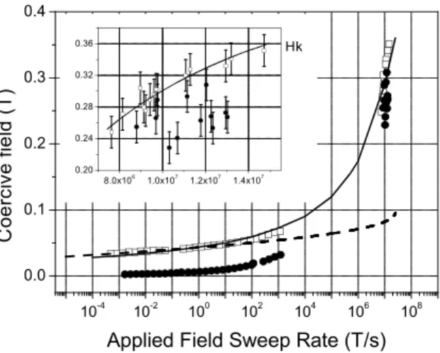
The possibility to pattern magnetic thin films has recently allowed the study of a single nucleation center. Moritz et al. have applied the droplet model to nucleation in perpendicular-to-plane magnetised dots obtained by electron beam lithography [35]. The dots had sizes of about 100×100nm2, allowing the hypothesis of only one nucleation center per dot. The dynamical investigations were carried out from the quasi-static region to the high dynamical regime, where the magnetic field was pulsed at the nanosecond time scale. They have shown that the droplet model was valid over more than 11 orders of magnitude of the applied field sweep rate as depicted in Fig. 5. By comparison, an attempt was made to fit the experimental data with a SW-type barrier and it is clear that in this case the droplet model describes nucleation processes better.
Concerning the temperature dependence of the coercive field, several papers relate nucleation volume extrapo-lations using a SW barrier type. This is usually valid in perpendicular-to-plane magnetised system where demag-netising effects favor nucleation [44]. Often, the onset of magnetization reversal in the hysteresis loops of these materials is quite abrupt, indicating that the nucleation field is larger than the propagation field. In that case, one can consider that the value of the coercive field is determined by nucleation and can be used to calculate the nucleation barrier using equations 2 or 3. As hysteresis measurements are performed in most cases in the quasi-static regime, it is possible to consider that the barrier height corresponds to ∆En= 25kBT and the critical
field can be deduced from this last expression.
Figure 4. Experimental hysteresis loops (open triangles) and simulated ones (full lines) measured on Au/Co/Au trilayers. A good agreement is found for low field sweep rates by using a SW barrier form with α = 1. Reprinted figure with permission from B. Raquet, R. Mamy, and J.C. Ousset, Phys. Rev. B. 54, 4128 (1996). Copyright 1996 by the American Physical Society.
10-4 10-2 100 102 104 106 108 0.0 0.1 0.2 0.3 0.4 8.0x10⁶ 1.0x10⁷ 1.2x10⁷ 1.4x10⁷ 0.20 0.24 0.28 0.32 0.36 Hk C o e rc iv e f ie ld ( T )
Applied Field Sweep Rate (T/s)
Figure 5. Variation of the dynamical coercivity vs. the applied field sweep rate measured in continuous (dots) and patterned (squares) Co/Pt thin film multilayers. The continuous line represents the calculations of HC using the droplet model; the dashed
one is the calculated HC deduced from the SW model. The inset shows a zoom for field sweep rates around 10 7
T/s (see Ref. [35]).
4.3. Nucleation centers and their distribution
The models given above consider homogeneous materials with homogeneous magnetic properties. In most real systems, defects and non-magnetic inclusions constitute potential nucleation centers in the case of thin film layers. Grain boundaries, or edges for magnetic nanostructures, present a local modification of properties such as anisotropy or exchange. Aharoni has calculated the nucleation field for anisotropy steps or regions with linear decrease of anisotropy and showed its strength was reduced with the size of the defect [45,46]. These models qualitatively account for a distribution of nucleation centers in real samples.
In the droplet model, it is possible to extend equation 5 when the domain wall energy is not homogeneous on the sample. Actually exchange and anisotropy are spatially distributed because of the granular structure. There might be also discontinuities in their profiles due to grain boundaries. As γ is not constant, it leads to another expression of the barrier height [24,35]:
∆En= πγ2t 2µ0MS (1 H − 1 H0 ) (7)
The critical field H0is defined as the maximum slope in the γ profile (see Fig. 6):
H0=
1 2µ0MS
(δγ
δr)max (8)
Modeling the reversal of magnetisation by using only one nucleation center and one nucleation barrier is most often a crude approximation, unless the field sweep rate or temperature are very low. Jamet et al. have extrapolated the nucleation length (related to the nucleation volume) and the mean distance between nucleation sites from their magnetic after-effect measurements performed on micrometer-size dots arrays [47]. The calculated values of 26 nm and 430 nm can be seen as twice the domain wall width and the distance separating two major defects in the continuous layer respectively. Concerning patterned layers approaching the domain wall width or the exchange length, it seems that nucleation centers can be generated by the nanofabrication itself (presence of edges for instance) or due to the extrinsic properties of the initial continuous magnetic layer [35]. In all cases, a nucleation field or nucleation energy distribution should be taken into account to simulate hysteresis or magnetic after-effect measurements [48,49,50].
The distribution of energy barriers for nucleation also accounts for statistical effects in the magnetisation reversal. At low field sweep rates, or at low temperature, the reversal is activated on only a few nuclei located on major defects. If the energy barrier for domain wall propagation is lower than the one for nucleation, the magnetisation rapidly reverses after the first nucleation and the hysteresis loop is quite square. In contrast, if the domain wall propagation barrier is high, nuclei can appear on many defects without inflating, so that the magnetisation will reverse by nucleation. The hysteresis loop morphology is then completely different [40]. Thomson and O’Grady used magnetisation data and hysteresis loops of Tb-Fe-Co films to determine energy barrier
γ
H
0γ
H
0Figure 6. Spatial fluctuations of the domain wall energy (due to local variations of anisotropy or exchange interactions). The critical field H0is seen as the maximum slope of γ. The black circle represents the position of the domain wall.
distributions, and the influence of this distribution on the relative contribution of domain nucleation and domain wall propagation to the magnetisation reversal [51]. Since domain wall propagation initiated at a limited number of nucleation centers is a relatively slow process, a distribution of energy barriers for nucleation in continuous films usually shows up as an increase of the nucleation rate at increasing applied field sweep rate [43,48]. Kerr microscopy and X-ray Photoelectron Emission Microscopy experiments performed on spin valves, magnetic tunnel junctions and exchange bias systems corroborate the dependence of nucleation rates on field sweep rate, field strength and local properties [38,52,53,54]. These measurements also show that due to the distribution of energy barriers, nucleation is quite a reproducible process in most magnetic thin films. Notable exceptions are high quality thin films that can be grown with very few defects, like some garnets containing Rare Earths [55]. The influence of thermal fluctuations on nucleation in the absence of defects has been simulated, for instance, by Rikvold et al. [58].
5. Nucleation in bulk materials
Most of the models and concepts discussed in the previous section can also be applied to the nucleation in bulk, 3-dimensional materials. The nucleation in homogeneous bulk magnetic materials has been considered by several authors. Broz, Braun and coworkers [59,60] developed a model where the nucleation took place through
a)
b)
c)
Figure 7. Increase of the nucleation density with applied field in the Fe20Ni80layer of a FeNi(4nm)/Al2O3(2.6nm)/Co(7nm) trilayer
[38,56]. The images were obtained using Photoelectron emission microscopy (PEEM) [57]. The applied fields were about 5.4, 5.8 and 6.4 mT for (a), (b) and (c) respectively.
the creation of a pair of Bloch or N´eel walls. This process is much faster than the propagation of already existing domain walls, but in infinite bulk materials it involves an infinite energy barrier. Aharoni and Baltensperger [39] considered spherical and cylindrical nucleation centers in a similar model, equivalent to the droplet model in the previous section. They showed that in that case the energy barrier for nucleation is still infinite at zero applied field, but will become finite when an external magnetic field is applied.
Reversal of the magnetization in bulk materials has been investigated especially for hard magnetic materials used in permanent magnets. The magnetization is often hard to saturate completely, and a number of 360◦domain
walls can persist in the material [61]. Though we did not discuss this before, this possibility also exists in 2D. When the field is applied in the opposite direction, reversal can take place by propagation of these existing domain walls. However, in order to obtain a fast reversal the nucleation of new reversed domains is necessary, since domain wall propagation is a relatively slow process. The heterogeneous, polycrystalline microstructure of these materials has a large influence on their magnetization reversal. Kronm¨uller et al. analysed the temperature dependence of Hc of high coercive field permanent magnets and compared it to the predictions of micromagnetic theories for
pinning and nucleation mechanisms [62]. They concluded that nucleation theory provided a better correspondance with experiment than pinning theory, if effects of misaligned grains, local stray fields and reduced anisotropies in grain boundaries were taken into account. Givord et al. [63] developed a model where the magnetisation reversal is associated with some critical volume proportional to the domain wall width γ, v(T ) ∝ γ3. They derived a
reversal field µ0HR(T ) ∝ A(T )/(v(T )2/3MS(T )). They found that the temperature dependence of the reversal
fields in ferrite and RE-FeB (RE = Rare Earth) magnets could be well explained by their model. The values for anisotropy and exchange interaction in the critical volume were close to the ones determined for the main phase. They concluded therefore that the reversal fields were not determined by initial nucleation at some defects.
6. Conclusions
Models for the nucleation of magnetisation reversal provide good agreement with experiment results for nanopar-ticles. In macroscopic systems, the onset of reversal by nucleation is in general determined by inhomogeneities in magnetic, structural and chemical properties, except for some very homogeneous materials with low defect densities like ferrimagnetic garnets. For other systems, macroscopic material parameters like exchange interac-tion, spontaneous magnetisation and magnetic anisotropy can be used to obtain an indication of nucleation fields, using different models. However, in general a distribution of energy barriers for nucleation exists giving rise to a dependence of the nucleation density on temperature and applied magnetic field. In this paper, we have discussed overcoming these energy barriers by thermal activation and/or applying a magnetic field. Recently, evidence of quantum nucleation by tunnel through the energy barrier has been observed in one-dimensional single-chain mag-nets [64]. Also, it has been shown that spin-polarised electron currents in uniformly magnetised layers can lead to domain nucleation [65]. These effects will probably call for new models for the nucleation of magnetisation reversal in the coming years.
References
[1] L. Landau and E. Lifshitz, Phys. Z. Sowjetunion 8 (1953) 153; T.L. Gilbert, Phys. Rev. 100 (1955) 1243; T.L. Gilbert, IEEE Trans. Magn. 40 (2004) 3443-3449.
[2] E.C. Stoner and E.P. Wohlfarth, Philos. Trans. London Ser. A 240 (1948) 599-642; L. N´eel, Acad. Sci. Paris 224 (1947) 1550. [3] H.W. Schumacher, C. Chappert, P. Crozat, R.C. Sousa, P.P. Freitas, J. Miltat, J. Fassbender, and B. Hillebrands, Phys. Rev.
Lett. 90 (2003) 017201.
[4] J. Miltat, G. Albuquerque, and A. Thiaville, in: B. Hillebrands and K. Ounadjela (Eds.), Spin Dynamics in Confined Magnetic Systems I, Topics in Appl. Phys. 83, Springer Berlin, 2002, 1-33.
[5] W.F. Brown, Rev. Mod. Phys. 17 (1945) 15. [6] W.F. Brown, Phys. Rev. 105 (1957) 1479-1482.
[7] E.H. Frei, S. Shtrikman, and D. Treves, Phys. Rev. 106 (1957) 446-455. [8] O. Fruchart and A. Thiaville, C.R. Phys. 6 (2005) 921-933.
[10] J.C. Slonczewski, IBM Research Memorandum No. 003.111.224 (1956). [11] A. Thiaville, Phys. Rev. B 61 (2000) 12221-12232.
[12] L. N´eel, Ann. Geophys. 5 (1949) 99.
[13] W.F. Brown, Phys. Rev. 130 (1963) 1677-1686.
[14] W. Wernsdorfer, E. Bonet Orozco, K. Hasselbach, A. Benoˆıt, B. Barbara, N. Demoncy, A. Loiseau, D. Boivin, H. Pascard, and D. Mailly, Phys. Rev. Lett. 78 (1997) 1791-1794.
[15] S.T. Chui and V.N. Ryzhov, Phys. Rev. Lett. 78 (1997) 2224-2227. [16] R.P. Cowburn and M.E. Welland, Phys. Rev. B 58 (1998) 9217-9226. [17] R.H. Victora, Phys. Rev. Lett. 63 (1989) 457-460.
[18] L. N´eel, Adv. Phys. 4 (1949) 191.
[19] A. Kirilyuk, J. Ferr´e, and D. Renard, EuroPhys. Lett. 24 (1993) 403-408. [20] H.-B. Braun, Phys. Rev. Lett. 71 (1993) 3557-3560.
[21] M. Lederman, S. Schultz, and M. Ozaki, Phys. Rev. Lett. 73 (1994) 1986-1989; R. O’Barr, M. Lederman, S. Schultz, W. Xu, A. Scherer, and J. Tonucci, J. Appl. Phys. 79 (1996) 5303-5305.
[22] W. Wernsdorfer, B. Doudin, D. Mailly, K. Hasselbach, A. Benoˆıt, J. Meier, J.-Ph. Ansermet, and B. Barbara, Phys. Rev. Lett. 77 (1996) 1873-1876.
[23] J. Ferr´e in: B. Hillebrands, K. Ounadjela (Eds.), Spin Dynamics in Confined Magnetic Structures I, Topics in Applied Physics 83, Springer, Berlin, 2002, p.127-165, and references therein.
[24] B. Barbara, J. Magn. Magn. Mater. 129 (1994) 79-86. [25] M.P. Sharrock, J. Appl. Phys. 76 (1994) 6413-6418.
[26] M. Yu, Y. Liu, A. Moser, D. Weller, and D.J. Sellmyer, Appl. Phys. Lett. 75 (1999) 3992-3995. [27] D. Givord, A. Lienard, P. Ternaud, and T. Viadieu, J. Magn. Magn. Mater. 67 (1987) L281-L285. [28] T. Schrefl, H.F. Schmidts, J. Fidler, and H. Kronm¨uller, IEEE Trans. Magn. 29 (1993) 2878-2880. [29] H. Zhou, H. Neal Bertram, and M.E. Schabes, J. Appl. Phys. 91 (2002) 8378-8380.
[30] O. Fruchart, B. Kevorkian, and J.-C. Toussaint, Phys. Rev. B 63 (2001) 174418; M. Eleoui, O. Fruchart, and J.-C. Toussaint, J. Magn. Magn. Mater. 283 (2003) 46-58.
[31] M. Grimsditch, A. Berger, J. Johnson, V. Metlushko, B. Ilic, P. Neuzil, and R. Kumar, Europhys. Lett. 54 (2001) 813-819. [32] D. Weller and A. Moser, IEEE Trans. Magn. 35 (1999) 4423-4439.
[33] B. Barbara and M. Uehara, Inst. Phys. Conf. Ser. 37 (1978) 204.
[34] R.D. Kirby, M. Yu, and D.J. Sellmyer, J. Appl. Phys. 87 (2000) 5696-5698.
[35] J. Moritz, B. Dieny, J.P. Nozi`eres, Y. Pennec, J. Camarero, and S. Pizzini, Phys. Rev. B 71 (2005) 100402. [36] H. L. Richards, S. W. Sides, M. A. Novotny, and P. A. Rikvold, J. Magn. Magn. Mater. 150 (1995) 37-50. [37] R. Skomski, J. Giergiel, and J. Kirschner, IEEE Trans. Magn. 32 (1996) 4576-4578.
[38] K. Fukumoto, W. Kuch, J. Vogel, F. Romanens, S. Pizzini, J. Camarero, M. Bonfim, and J. Kirschner, Phys. Rev. Lett. 96 (2006) 097204.
[39] A. Aharoni and W. Baltensperger, Phys. Rev. B 45 (1992) 9842-9849. [40] E. Fatuzzo, Phys. Rev. 127 (1962) 1999-2005.
[41] M. Labrune, S. Andrieu, F. Rio, and P. Bernstein, J. Magn. Magn. Mater. 80 (1989) 211-218.
[42] J. Pommier, P. Meyer, G. P´enissard, J. Ferr´e, P. Bruno, and D. Renard, Phys. Rev. Lett. 65 (1990) 2054-2057. [43] B. Raquet, R. Mamy, and J.C. Ousset, Phys. Rev. B 54 (1996) 4128-4136.
[44] S. Lemerle, Ph.D. Thesis, Universit´e Paris-Sud (1998). [45] A. Aharoni, J. Appl. Phys. 30 (1959) S70-S78. [46] A. Aharoni, Phys. Rev. 119 (1960) 127-131.
[47] J.P. Jamet, S. Lemerle, P. Meyer, J. Ferr´e, B. Bartenlian, N. Bardou, C. Chappert, P. Veillet, F. Rousseaux, D. Decanini, and H. Launois, Phys. Rev. B 57 (1998) 14320-14331.
[48] P. Bruno, G. Bayreuther, P. Beauvillain, C. Chappert, G. Lugert, and D. Renard, J. Appl. Phys. 68 (1990) 5759-5766. [49] G. Bottoni, D. Candolfo, and A. Cecchetti, J. Magn. Magn. Mater. 195 (1998) 754-758.
[50] S. Rohart, V. Repain, A. Tejeda, P. Ohresser, F. Scheurer, P. Bencok, J. Ferr´e, and S. Rousset, Phys. Rev. B 73 (2006) 165412. [51] T. Thomson and K. O’Grady, J. Phys. D: Appl. Phys. 30 (1997) 1566-1576.
[52] Y. Pennec, J. Camarero, J.-C. Toussaint, S. Pizzini, M. Bonfim, F. Petroff, W. Kuch, F. Offi, K. Fukumoto, F. Nguyen Van Dau, and J. Vogel, Phys. Rev. B. 69 (2004) 180402.
[53] F. Romanens, S. Pizzini, F. Yockaichiya, M. Bonfim, Y. Pennec, J. Camarero, J. Vogel, J. Sort, F. Garcia, B. Rodmacq, and B. Dieny, Phys. Rev. B 72 (2005) 134410.
[54] J. Moritz, C.O. Coileain, G. Feng, K. Nakajima, S. Van Dijken, and J.M.D. Coey, J. Magn. Magn. Mater. 296 (2006) 118-123. [55] A.P. Malozemoff and J.C. Slonczewski, Magnetic Domain Walls in Bubble Materials, Academic Press, New York, 1979. [56] J. Vogel, W. Kuch, R. Hertel, K. Fukumoto, F. Romanens, J. Camarero, S. Pizzini, M. Bonfim, F. Petroff, A. Fontaine, and
J. Kirschner, Phys. Rev. B 72 (2005) 220402(R). [57] W. Kuch, Phys. Scr. T109 (2004) 89-95.
[58] P. A. Rikvold, G. Brown, S. J. Mitchell, and M. A. Novotny, in : D. Shi, B. Aktas, L. Pust, and F. Mikailov (Eds.), Nanostructured Magnetic Materials and their Applications, Lecture Notes in Physics, Vol. 593, Springer-Verlag, Berlin, 2002, pp. 164-182.
[59] J.S. Broz, H.B. Braun, O. Brodbeck, W. Baltensperger, and J.S. Helman, Phys. Rev. Lett. 65 (1990) 787-790. [60] H.B. Braun, IEEE Trans. Magn. 27 (1991) 4787-4789.
[61] P. Gaunt and C.K. Mylvaganam, J. Appl. Phys. 48 (1977) 2587-2590.
[62] H. Kronm¨uller, K.-D. Durst, and M. Sagawa, J. Magn. Magn. Mater. 74 (1988) 291-302. [63] D. Givord, M. Rossignol, and V.M.T.S. Barthem, J. Magn. Magn. Mater. 258-259 (2003) 1-5. [64] W. Wernsdorfer, R. Cl´erac, C. Coulon, L. Lecren, and H. Miyasaka, Phys. Rev. Lett. 95 (2005) 237203. [65] J. Shibata, G. Tatara, and H. Kohno, Phys. Rev. Lett. 94 (2005) 076601.


![Figure 7. Increase of the nucleation density with applied field in the Fe 20 Ni 80 layer of a FeNi(4nm)/Al 2 O 3 (2.6nm)/Co(7nm) trilayer [38,56]](https://thumb-eu.123doks.com/thumbv2/123doknet/13577915.421778/10.892.133.767.767.1001/figure-increase-nucleation-density-applied-field-layer-trilayer.webp)
