HAL Id: hal-00986875
https://hal.archives-ouvertes.fr/hal-00986875
Submitted on 5 May 2014
HAL is a multi-disciplinary open access
archive for the deposit and dissemination of
sci-entific research documents, whether they are
pub-lished or not. The documents may come from
teaching and research institutions in France or
abroad, or from public or private research centers.
L’archive ouverte pluridisciplinaire HAL, est
destinée au dépôt et à la diffusion de documents
scientifiques de niveau recherche, publiés ou non,
émanant des établissements d’enseignement et de
recherche français ou étrangers, des laboratoires
publics ou privés.
to Support Expert Diagnostic
Alexandre Krupa, David Folio, Cyril Novales, Pierre Vieyres, Tao Li
To cite this version:
Alexandre Krupa, David Folio, Cyril Novales, Pierre Vieyres, Tao Li. Robotized Tele-Echography: an
Assisting Visibility Tool to Support Expert Diagnostic. IEEE Systems Journal, IEEE, 2016, 10 (3),
pp.974-983. �10.1109/JSYST.2014.2314773�. �hal-00986875�
Robotized Tele-Echography: an Assisting Visibility
Tool to Support Expert Diagnostic
Alexandre Krupa, David Folio, Cyril Novales, Pierre Vieyres and Tao Li
Abstract—This paper presents a robotized tele-echography system with an assisting visibility mode that helps the medical expert diagnosis. This autonomous mode is based on a multitask control approach that maintains the visibility of an anatomic element of interest while the medical expert tele-operates a 2D ultrasound probe held by a 4-DOF robot. The main task is used to automatically maintain several visual constraints that guarantee an intersection between the US image plane and the organ of interest. A secondary task allows the medical expert to manually apply the probe motion through the tele-operation mode. The main advantage of this approach is to give to the clinician the control of all the degrees of freedom of the probe to examine the patient while automatically preserving the visibility of the organ of interest when required. Experimental results, performed on a phantom and human abdomen, demonstrate the efficiency of the visibility assistance task.
Index Terms—Robotized tele-echography, Ultrasound-based visual servoing, visibility constraints.
I. INTRODUCTION
M
Edical ultrasound (US) exam is a low cost, reliable and non-invasive technique used in routine ante natal care for medical investigations of the heart, abdomen, kidneys and liver, and for breast cancer investigations. It is an important diagnostic tool in both routine and emergency care. Since the mid-nineties there is a lack of US experts in developed and developing nations globally, and a growing number of medically isolated settings. Therefore, delivering equitable healthcare in these isolated regions or to scattered populations is a challenge; the access to these specialized medical exams is only achieved through the use of dedicated applications, which allow the experts to perform remote consultations, providing faster responses in routine, emergency or crisis situations. Especially, severals clinical trials on the robotized tele-echography concept have been conducted between various main radiology centers and isolated sites [1], [2], [3]. These studies showed that 90% of concordance between standard echography acts and those carried out with the robotic tele-echography system. Furthermore, at the medical level, there was not a single false positive or false negative in any of these examinations, for which a time limit of 20 minutes was applied. Under these considerations, there are no need for a This works has been presented in part a the IEEE Int. Conf. on Intelligent Robotics and Automation, St. Paul, MN, May 14–18, 2014.A. Krupa and T. Li are with Lagadic Team, Inria Rennes–Bretagne Atlantique, IRISA, Rennes 35042, FRANCE; (e-mail: [email protected]). D. Folio is with INSA-CVL, Univ. Orl´eans, PRISME EA 4229, Bourges, France; (e-mail: [email protected]).
Cyril Novales and Pierre Vieyres are with Univ. Orl´eans, INSA-CVL, PRISME EA 4229, Bourges, France; (e-mail:[email protected])
patient to be moved towards an ultrasound expert center nor to displace a specialist next to the remote patient. Nowadays, the robotized concept is more reliable than the basic tele-ultrasound modality presented in the 90’s in [4], [5]. Therefore, remote robotized echography, using a mobile lightweight tele-echography robot, is one major solution that could satisfy this type of health-care need to benefit isolated populations.
Several research teams, such as [6]–[11], have been de-veloping, under various constraints and objectives (e.g. ultra-sound scan, needle insertion, prostate biopsy. . . ), tele-operated robotized tele-echography systems using portable ultrasound device via standard communication networks (ISDN, internet, satellite, etc.). Some of these proposed systems showed the development of dedicated concepts, generally called body-mounted devices, that are usually positioned on the patient’s body thanks to the reduced dimensions and their lightweight mechanisms. As an example of the kinematic performances of these concepts, one can refer to [11], [12] for parallel mechanisms and to [13], [14] for serial or hybrid structures. In [15], Nouaille et al. showed that, among these structures, a 4 degrees-of-freedom (DOF) light-weight spherical wrist robot is a good candidate to satisfy the strong constraints of mobility, accessibility to any medically isolated place and kinematic performances of the tele-operated device to enable an accurate follow-up of the expert gestures at a distance.
However, these lightweight body-mounted structures, when maintained on a patient’s body by a paramedic, are subjected to patient’s physiological movements or to unexpected moves of the paramedic. These perturbations, eventually enhanced during the teleoperation mode, cause the loss of the region of interest located in the 2D ultrasound images, hence disrupting the sonographer diagnosis during the tele-operated echography act. This work presents some new assistance tools, referred to as autonomous modes, to enhance the performance of these robotized systems in terms of diagnosis capabilities during the teleoperated act. In particular, we propose to improve this tele-operated task by combining the robot body-mounted structure with an ultrasound based visual servoing (US-IBVS) used as a visibility assistance tool.
The paper is organized as follow. First in Section II the overall robotized tele-echography system is presented. Then in Section III the proposed autonomous mode is described. The Section IV shows some experimental results of the enhanced tele-echography procedure using the autonomous mode. A conclusion is given in Section V.
(i) Expert site (ii) Communication (iii) Patient site links (eg, internet, satellite...) Ambiant videoconference Ambiant videoconference I/ O cont rol l ogi c I/ O cont rol l ogi c (b) (d) (e) (c) (a) GUI US slices 3D Volume Autonomous mode control strategies Image Processing Low-level controller US slices z+F s US probe Robot Haptic probe Supervision Tele-operation Mode selection q1, q2, q3 Measures: US images Teleoperation High-level management Set points: (a) Videoconference system Supervision PC Linux/RTAI kernel (ContrACT) Low-Level Controller Windows CE High-Level Controller Linux/RTAI kernel (ContrACT) 3D Reconstruction, IHM PC Linux (Qt) Image Processing PC Linux (VisP) Haptic Probe +Virtual probe PROSIT ROBOT Medical US Probe Low-Level Controller Windows CE Videoconference system (b) Fig. 1. The robotized tele-echography system: (a) overall architecture diagram, and (b) the system hardware.
II. ROBOT-AIDEDTELE-ECHOGRAPHYSYSTEM
A. The Robotized Tele-Echography Architecture
1) Remote robotized echography: Classically, a robotized tele-echography system is composed of three main parts, as depicted in Fig. 1a: i) the expert site is the master station located at an expert medical center where the ultrasound expert sends robot controls using a haptic probe and is fed back with the patient ultrasound (US) images; ii) the communication links could be either a terrestrial or satellite link, based on wired or wireless data transmission protocol; and iii) the patient site is made up of the robotic system with its control unit, an US probe and device, and the paramedical staff who deploys the patient station, sets up and supervises the remotely controlled examination, and assists the distant sonographer. More precisely, the medical expert handles a haptic probe that he uses similarly as a standard US probe (cf. Section II-C). The low level controller computes the haptic probe positions using an inertial measurement unit (IMU) sensor, and then sends Euler orientation angles to the patient site supervision computer, as shown in Fig. 1. This workstation controls the probe holder robot, positioned on the patient by the paramedi-cal assistant, via a low level controller. The US images are sent to the expert to close the tele-operated loop. In addition, the expert can also activate some autonomous modes to perform an ultrasound image-based visual servoing (US-IBVS), and store US slice images in the local GUI. This GUI allows a post-treatment 3D reconstruction of the scanned US data, and enables the medical expert to perform an off-line sonography act. Thanks to the autonomous mode, the practitioner can then either retrieve a pre-stored US slice position, or reach an US slice extracted from the virtual 3D volume.
For a more friendly usage a videoconferencing system is usually mandatory. This videoconferencing system allows to enhance the overall tele-operated act by exchanging ambient images and audio between expert and patient sites.
2) The Hardware System: The hardware device is thus divided in two parts (see Fig.1b). i) The patient part (right side) with the PROSIT robot that holds the US probe on the patient. Articular low level controller is managed through a dedicated
Windows CE workstation. The main supervisor controller is built upon a PC with ContrACT robotic middleware [16], presented in the following. A second computer realizes the image processing of the US images. ii) The expert part (left side) allows the sonographer to control the remote robot with a haptic device. The high-level controller uses the same robotic middleware, and manages this haptic probe through a Windows CE workstation. A GUI and vision computer allows the practitioner to monitor and tele-operate the US probe. On both sides, two visioconference systems enable communication between the doctor, the paramedic and the patient. The link between the two sites can be an Internet, RNIS or satellite communication link.
3) The Software System: In addition, to ensure reliable and safe robotized tele-echography, it is necessary to provide the best transparency and robust solutions during the tele-echography procedures. Especially, the software environment is one of the essential part of the robotic system. Hence, in this work, the tele-echography system is based on the ContrACT real-time middleware [16] (built upon a Linux/RTAI kernel). The programming model of ContrACT relies on the concept of module, which is an independent real-time software task that reacts to a set of predefined requests and communicates with other modules by the mean of ports [16]. Thus this real-time middleware enhances evolution, modularity and re-usability, and avoids redesign costs. Furthermore, the communication between the expert and patient sites usually implies some variable time-delay in the tele-operative control process. To overcome this issue, ContrACT provides an applicative real-time scheduler which embeds observation, memorization and statistic computation of modules execution run-times for au-tomatic adaptation of the modules behaviors to the execution context [17]. With this control architecture, the robotized tele-echography system has an adaptive decision mechanism that is decomposed into a hierarchy of independently reusable supervisors, each one managing a specific responsibility in the tele-echography process.
There are two main modes of control illustrated on Fig.1a: the manual tele-operated mode based on geometric model
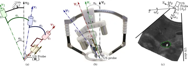
α0 α1 α2 {Rp} q1 q3 q2 z ψ3 ψ2 ψ1 ψ0 US Probe (a) q1 q3 q2 z ψ3 ψ2 α0 ψ1 ψ0 US probe (b) U S sl ice
s
y x z {Rp} US Probe ωx ωy ωzvz (c)Fig. 2. The PROSIT robotic system: (a) kinematic diagram of the tilted serial spherical wrist structure; (b) photographic view of the tele-operated system; (c) probe frame with a section of the organ of interest (OI).
control and the automatic modes based on kinematic model control. In both modes, Euler position of the virtual probe handled by the sonographer are sent through the communica-tion link from the expert site (left side of Fig.1a) to the expert site. However these controls, for both modes, are processed differently at the patient site. In manual mode, the virtual probe Euler positions are transformed in articular positions for the robot using inverse geometric mode. The robot is not controlled by an Invert Kinematic Model to be robust in case of lacks of transmitted data: the robot will never diverge and will simply stop on fails. In automatic modes, the processing algorithms use locally kinematics model. As a consequence, inverse kinematics model is used when these modes are selected.
B. The Robotic System
When designing an optimal robotic structure for tele-echography several parameters have to be taken into account: minimal workspace, probe movement accuracy, a lightweight structure (less than3 kg to be withstood by the patient), robot compactness to facilitate the examination and transportation. These constraints are contradictory and the optimal solution leads to a compromised design criteria given by spherical wrist structures with concurrent axes; these are good candidates to satisfy most criteria, but present singularities within the workspace. Nevertheless, the choice of such serial spherical robot usually brings forth two issues.
1) Kinematic Issue: First, similar to all poly-articulated mechanisms, the kinematic of a serial spherical wrist presents singularities within the operational space, and leads to position trajectory errors of the effector. The singularities studies could be achieved by considering the robot’s kinematic model. This model allows to determine the relationship between the US probe velocities v = (v, ω), and the vector of joint rates
˙
q = ( ˙θ1, ˙θ2, ˙θ3, ˙r4) (Fig. 2a). Hence, the kinematic model could be expressed here as:
v= v ω ! = J · ˙q = A C B 03×1 ! · ˙q (1)
Only the 3 rotations are required to position and orientate the probe, whereas the translation is only used to maintain a safe contact force between the US probe and the patient’s skin (cf. Sect.III-D). In the following, we focus on the rotation motion, as the translational motion could be obtained from:
v= ω ∧ (0 0 r4)T+ (0 0 ˙r4)T (2) The rotational kinematics ω= Jω· ˙q in the probe frame {Rp} is defined by [15]: Jω= sα1cα2cθ2sθ3+ sα1sθ2cθ3 sα2sθ3 0 0 +cα1sα2sθ3 sα1cα2cθ2cθ3+ −sαssθ2cθ3 sα2cθ3 0 0 +cα1sα2cθ3 cα1cα2− sα1sα2cθ2 cα2 1 0 (3) with αi−1 the angle between each link (Fig. 2a). As these angles are set to αi−1 = 22.5◦, the spherical wrist singu-larities are encountered when θ2 = kπ. To avoid the central singularity, which is a position favored by the expert during the echography, PROSIT has a serial spherical wrist tilted away from the normal of the patient’s skin (Fig. 2b). This is performed by introducing a tunable tilt angle α0 on the main axis with respect to the normal Ψ0 of the patient’s skin. This system enables to reject the central singularity out of the workspace favored by the US expert during the tele-echography act.
2) Dynamic Issue: The second issue is related to the robot mass; its lightweight renders the robot sensitive to the patient’s physiological moves and to the mishandling by the operator during the tele-operation. These two perturbations may generate small unexpected robot’s displacements on the patient’s body leading to the loss of points of interest within the fed back US image, on which the expert relies on to give a diagnosis. In these situations, the robot may have to be repositioned on the patient’s body by the assistant in order to help the expert to find the original investigated organ. Therefore, a robotic control mode is useful to automatically maintain the visibility of the anatomical element of interest
in the 2D US image while the expert tele-operates the haptic probe [6].
C. The Tele-Sonographer Interactive System
The medical expert manipulates a haptic probe during the tele-echography procedure. As illustrated in Fig.3, the haptic probe usually looks like real US probe. The haptic device has to provide a good rendering of the distant interactions between the robot and its environment. This probe can be either i) passive that is recording only the expert’s movements; ii) pseudo-haptic that is having a spring to simulate the compliance of the patient’s body; or iii) fully-haptic, that is the probe being actuated to render the force exerted by the ultrasound probe on the patient’s skin.
(a) (b) (c)
Fig. 3. Different haptic probes: (a) passive probe, (b); pseudo-haptic probe, and (c) fully-haptic probe.
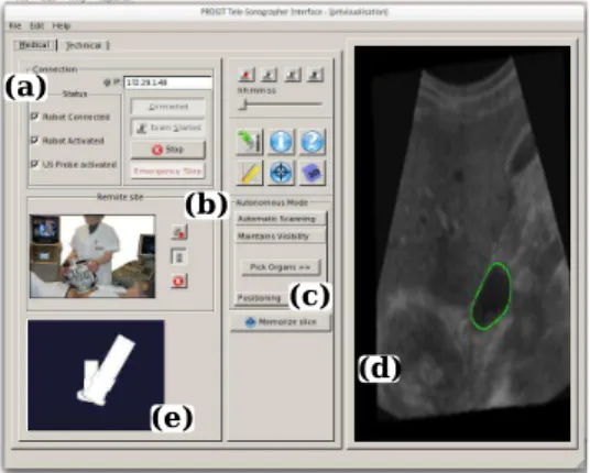
Furthermore, performing a robotized tele-echography via specific networks requires the knowledge of the accurate positioning of the robot’s end-effector with respect to the haptic probe’s current position. This information has to be em-bedded in the telesonographer Graphic User Interface (GUI) to provide better information about the remote robot’s behavior. As illustrated in Fig. 4, the developed telesonographer GUI is composed of different parts: (a) the connection panel, (b) the visioconference management panel, (c) the task selec-tion panel, (d) the 2D ultrasound image flow, and (e) the virtual probes display. The virtual probe display represents
(b)
(d) (e)
(c) (a)
Fig. 4. The telesonographer GUI at the master site.
the orientation of the haptic probe and the robot’s end-effector, and consists of three parts: the mobile element held by the medical expert, the end-tip of the probe representing
the ultrasound sensor capturing the ultrasound images and one element joining the two previous ones. This will help the expert to perform his remote medical act with the best rendering of the distal interactions between the robot and the patient.
D. Tele-Echography Procedure
During the tele-echography act, a paramedical assistant positions the probe holder robotic system on a predetermined anatomical location and maintains it on the patient’s body. The medical expert could then remotely control the robotic system. The patient’s US images are fed back to the specialist who analyzes them either in real time or after the tele-echography act by exploring the recorded data to provide his diagnosis. Using our proposed tele-echography system, the sonographer could operate in different modes: a fully tele-operated mode and automated mode, described in the following.
1) Tele-Operated Mode: Using a haptic probe, the medical expert uses it to control the orientations of the remotely located robot. Information on the movements of the haptic probe, acquired from an IMU sensor, is sent to the patient site the Euler angle to move the real tele-operated echographic probe held by the robot end-effector.
A robot-aided tele-echography system must provide, for the medical expert, the best working conditions for a remote medical consultation and ensure safety for the patient. Never-theless, the communication links between expert and patient site introduce some variable time-delays. For instance, in [18] is reported a time-delay of about 1 s with a standard devi-ation of 200 ms using an Inmarsat satellite communication. This communication constraint may lead to disturbances and deteriorates the trajectory tracking generated by the expert. The chosen system architecture built upon ContrACT real time middleware ensures that the overall tele-echography tasks are effectively realized in time. However, the design of dedicated control strategies is still required to maintain stability and transparency in the tele-operated system. The tele-operated system is fully transparent under two conditions: i) the robot end-effector holding the US probe reproduces the same orien-tations as the one generated by the practitioner manipulating the haptic probe, and ii) the force rendered by the haptic probe reflects the force exerted by the US probe on the patient’s body. To this aim, different bilateral control architectures have been developed [18]. These control aspects will not be considered in this paper as we will focus on maintaining the visibility of the regions of interest that could be lost by unexpected moves at the patient sites (i.e. patient physiological moves and paramedic moves).
2) Autonomous Mode: During the tele-echography act some tasks could be achieved autonomously, and thus assisting the medical expert in making his diagnosis. To this aim, the expert sonographer is also able to select some predefined tasks that are performed autonomously. Those tasks are related to the
autonomous modein which the following automatic operations are realized:
M1. Automatic scanning: builds a 3D volume from several 2D US images, and then offers to the expert its off-line virtual exploration;
M2. Maintain visibility of an organ: shares the control be-tween the tele-operation task and an US visual servoing; M3. Autonomous positioning #1: reaches a pre-memorized
position by the ultrasound expert;
M4. Autonomous positioning #2: reaches an US slice ex-tracted from the virtual 3D volume.
These different autonomous modes provide more flexibility to the system and to the sonographer. At any time, the sonog-rapher can go back to the full tele-operation control mode. On the patient side, the autonomous mode control strategies are implemented and provide the positions or velocities to the robotized tele-echography system low-level controller, as illustrated in Fig. 1a.
III. AUTONOMOUSMODE:ANASSISTINGTOOL FOR
TELE-ECHOGRAPHY
To perform robotized tele-echography, the literature pro-vides many different teleoperated procedures. Hence, different bilateral control architectures based on wave variable are presented in [18]. In this work, we propose to enhance the tele-echography process thanks to some autonomous modes. In this section, first, the ultrasound image-based visual servoing (USIBVS) principle is introduced. Then, US-IBVS is extended to maintain the visibility of a selected organ. Finally, we briefly present the forces control scheme of the US probe in contact with the patient’s skin.
A. Ultrasound Image-based Visual Servoing (US-IBVS)
The autonomous positioning of the robotized US probe to reach either a previously memorized cross section (M3) or retrieve a slide extracted from the virtual 3D volume (M4), is designed using image-based visual servoing (IBVS) approaches [19]. Classically, IBVS methods aim at controlling the robot motion using visual data from image acquired by a vision system. In this study, the US image is used to provide information in its observed plane. Therefore, suitable features need to be used to control not only the in-plane velocity (ωx) but also the out-of-plane velocities (ωy andωz) of the 4-DOF robot (Fig. 2c) to reach the desired section in sight. In this work, based on our previous approach presented in [20], we use the US image momentsmij =
RR Sx
iyjdxdy as feedback to the control scheme. Thus, this US-IBVS feedback is defined by the set s of visual features that has been chosen as:
s= (xg, yg, d) (4)
with (xg = mm10
00, yg =
m01
m00) the 2D coordinates center of
mass of the section of interestS, and d =√m00is the square root of its surface. To design the control law of the US-IBVS, we analytically determined in [20] the relation between the variation ˙s of the US image visual features s that is induced by the probe motion v, that is written as [19], [20]:
˙s = Lsv (5)
where Ls denotes the interaction matrix related to the US image visual features1 s. The interaction matrix can be for-mulated as: Ls = [Lv Lω], with its translational Lv and
1See [19] or [20] for further details about the interaction matrix.
angular Lω parts. In our case, only the rotational velocities ω= (ωx, ωy, ωz) are visually servoed. Thus, considering only the rotational velocities ω, the relation (5) can be reduced to:
˙s = Lωω (6)
In classical IBVS methods, desired values s⋆ are defined for each visual data s. Hence, a kinematic controller can be determined by imposing an exponential convergence to the error e= (s − s⋆) to zero, that is [19]:
ω= −λbL+ω(s − s⋆) (7)
whereλ > 0 is the control gain, and bL+
ωis the Moore-Penrose pseudo inverse of an estimation of the interaction matrix Lω related to the set of visual features (4). According to [19], the control law (7) is known to be locally asymptotically stable when the estimation bLωof Lωrespects the following sufficient condition:
b L+
ωLω> 0 (8)
B. Feature Tracking in Ultrasound Images
To compute the required visual features (4), a segmentation of the section of interest S are mandatory. This can be done by active contours (or snake) [21]. To this aim, a robust image processing algorithm that detects and tracks the contourC of S from US image in real time is required. We applied the recursive parametric active contour (snake) we presented in [22], to extract the contour from US images. The contour parametrization we used is based on the Fourier descriptors in order to extract both concave and convex shape as illustrated in the Fig.5. To ensure the real time (25 frames/second) contour detection and tracking, we developed a GPU implementation of the snake algorithm using CUDA library.
(a) (b)
Fig. 5. Snake feature tracking in US images: (a) contour detection of convex and (b) concave objects.
C. Visibility Assistance Task
The robotic task proposed here is to automatically maintain the visibility of an organ of interest (OI) in the US plane while the medical expert, using the haptic probe, tele-operates the distant robot. The different successive steps are: i) the medical specialist tele-operates the 4-DOF of the robotized probe to reach a section of an OI, as in Fig. 2c; ii) the sonographer activates the visibility assistance task by clicking inside the section of the organ that is then automatically segmented
thanks to a real-time active contour algorithm such as one proposed in [22]; iii) then he pursues the exploration of the organ by freely tele-operating all the 4-DOF while the system automatically prevents the loss of the organ visibility by acting like an active virtual guide. The aim of the assistance task is to automatically maintain the section center in an image region xg ∈ [x−, x+], yg ∈ [y−, y+] and a minimum section area d ≥ d−
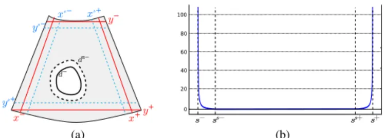
that guarantees an intersection between the organ and the US plane. The retained solution to insure the visibility constraints is to trigger a visual servo control when at least one visual feature goes outside a safe interval defined by xg ∈ [xs−, xs+], yg ∈ [ys−, ys+] and d ≥ ds− where the section is still visible as illustrated on Fig.6a. In [23], a concept of triggering visual servo control was presented where a 6-DOF robot actuating a camera was controlled by mixing an image-based and position-based visual servoing approaches. By adapting this concept to our application case, we get the following control law:
ω= −λ(HbLω)+H(s − s∗) (9)
where λ > 0 is the control gain, ω is the 3D rotational velocity to apply to the probe. Note that we do not consider in the visibility task the control of the translation along the main axis of the probe since this DOF is exclusively tele-operated by the clinician to keep the probe in contact with the patient’s skin. H= Diag(h1, h2, h3) is a diagonal weighting matrix whereh1,h2,h3are varying weights associated to the three visual features. Since the visual features do not have to converge exactly to their desired values but only go back in the safe area, the goal is different. Thus, a varying weight is affected on each visual feature to servo them only if they leave the safe interval. Fig. 6b presents the weighting function hi that is considered for each feature. Its formulation is given herein for the featurexg and is similar for the other ones:
h1(xg) = xg−x s+ x+−x g ifxg> x s+ xg−xs− x−xg ifxg< x s− 0 otherwise (10)
With this approach, the visual constraint related to one feature is activated as soon as its weight is non-null and deactivated when the considered feature goes back in the safe area. However, as the rank of HbLω can switch from 3 to 0 when the visual features come back in the safe area, this control law will lead to discontinuity issues during the rank switching as we showed from a simulation study presented in our previous work [24]. We therefore propose to replace the classical Moore-Penrose pseudo-inverse operator by the continuous pseudo-inverse operator proposed in the framework of varying-feature-set [25] to avoid these control law discon-tinuities. However, the formulation of this continuous inverse operator is appropriate for weights between 0 and 1. As H is defined up to a scale factor, we define therefore a normalized weighting matrix Hn as:
Hn= ( H ifkHk∞≤ 1 H/kHk∞ else (11) (a) (b)
Fig. 6. (a) Visibility constraint (plain red) and safe (dotted blue) intervals defined for xg and yg; minimum (plain black) and safe (dotted black) values
are defined for d. (b) Weighting function: hiis null in the safe interval and
increases to the border
We denote L LH
n
ω the continuous inverse of Lω with the
weighting matrix Hn(see [26] for the analytical computation). The control law that ensures the visibility constraints is therefore given by : ω= −λL LH n ω (s − s ⋆) (12) This way, only the DOF required to maintain the visibility of the activated feature(s) is/(are) constrained by the visual servo and it is therefore possible to control the remaining DOF by tele-operation thanks to the redundancy formalism [27]. This is achieved by applying the following final control law that we propose in order to fuse the visibility task with a secondary task corresponding to the tele-operation control:
ω= −λL LH n ω (s − s ⋆ ) + PLH n ωm (13) with PLH n = I3− L LH n
ω Lω, and ωm is the 3D rotational velocity that is measured from the haptic device manipulated by the medical expert during tele-operation. Here PLHn is the projector operator proposed in [26] for the varying-feature-set framework that projects the component of ωm on the null space of the visibility task in order that the tele-operation task does not disturb the visibility one.
The fundamental issues related to the stability of the above control law (13) that fuses the visibility and tele-operation tasks will now be discussed. When all the visual features are fully activated by the visibility task (i.e. the organ of interest cross the visibility constraint), the sole control law (7) is applied since the weighting matrix Hn is equal to the identity matrix, and then the projection operator PLH
n is null. The
asymptotic local stability is therefore insured as soon as the well-known condition (8) is respected [19]. In the opposite case, when all the visual features are deactivated (i.e. the organ of interest cross is inside the safe area), the control law corresponds then to a fully teleoperated mode (ω= ωm), that applies directly the input velocity sent by the medical expert. So, in this second case no stability issue has to be considered since the probe reproduces directly the motion of the expert. In the transition case, when at least one or two feature(s) is/(are) activated, the visibility task can not be perturbed by the tele-operation task thanks to the use of the projection operator PLH
n. Actually, thanks to the redundancy formalism, the
condition (8) is also sufficient to insure the asymptotic stability of the system [27].
D. Force Control to Maintain the Probe/Patient’s Skin Contact
As introduced in Sect.II-B1, the translational velocity is obtained from (2). As one can see, the z-axis translation of the PROSIT end-effector is totally decoupled from its orien-tation wrist mechanism. Therefore, to automatically maintain the probe contact, an independent force controller that only actuates the vz translational velocity is implemented. Thus, we applied here the following simple force regulation law that was used in [28]: vz= − K σ (fz− f ⋆ z) (14)
where fz and fz∗ are respectively the gravity-compensated force measure along the end-effector z-axis and the desired force to achieve;σ is an estimate of the contact stiffness; and K is a positive proportional control gain. In particular, the patient skin is modeled here by a simple spring of constant stiffnessσ. A more efficient adaptive force controller may also be used like in [29] where a varying viscoelastic model was considered. Finally, as translational motion (14) is decoupled from the rotational motion ω (ie. (7) for full US-IBVS, or (13) for visibility assistance task), the overall system local stability could be ensured.
IV. EXPERIMENTALRESULTS
To validate the proposed robotized tele-echography system, two different scenarios are considered. First, an anthropomor-phic arm is used as the robotic system to evaluate the overall framework. Then, the concept is implemented on the medical PROSIT platform in order to be tested on an US abdominal phantom and then on a human volunteer.
A. Visibility Assistance Results with an Anthropomorphic Robot
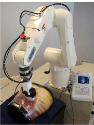
Foremost, the autonomous mode is tested on an experimen-tal setup consisting of a 6-DOF anthropomorphic robot holding a 3-5 Mhz convex US probe that interacts with a realistic abdominal phantom (see Fig 7). We purposely constraint the motion of the robot to simulate the 4-DOF kinematic of the PROSIT robot by applying only the velocity vector v to the probe (1). Moreover, in order to automatically keep the contact between the probe and the phantom, we regulated the vz velocity by the independent force control scheme (14) to maintain af∗
z = 1 N contact force.
In a first experiment, the user performed an exploration of the phantom by tele-operating the rotational velocities of the probe without enabling the visibility assistance mode. The operated velocities are represented in Fig. 8b. As expected, during this pure tele-operation mode without visibility assis-tance, the surface of interest leaves the image as seen in Fig.8a where the trajectory is displayed in white when the feature leaves the visibility region. White parts do appear in Fig.8a at both extremities, revealing that xg leaves the acceptable interval. Furthermore, the object area is particularly small in Fig.8a and can be entirely lost.
In a second experiment, we activated the visibility assistance mode by applying the control law (13) where we fixed the
Fig. 7. The first experimental setup is composed by a 6-DOF anthropomorphic Viper (Adept) robot holding a US probe that interacts with a realistic abdominal phantom
control gain to λ = 0.4 and we set the desired values of the visual features to (x∗
g, y ∗
g) = 0 m (the center of the image) and d∗
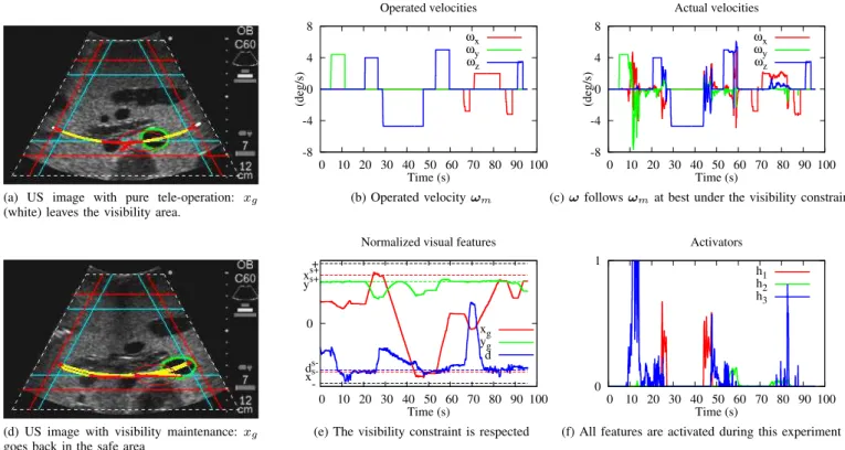
= 0.021 m. To compare the results, we considered as input the same operated velocities that were sent by the user during the pure tele-operation previous experiment. Fig.8d shows that active control prevents the object from leaving the image since the trajectory does not pass the red lines, and the object section area is kept sufficiently large in the image. The trajectory of the center of gravity is displayed in yellow when no constraints are taken into account and in red when at least one constraint is activated. We can note that three red parts are visible: on both sides of the image, which means xg was leaving its safe interval, and in the middle of the image, that corresponds to the activation of yg. This observation is confirmed by Fig.8e that shows the evolution of the features in full lines and their interval limits in dashed lines. The evolution of xg (red) shows that it first approaches its upper limit (t = 30 s), then approaches its lower limit (t = 45 s). This corresponds to the extremities of the trajectory. The upper limit of yg (green) is approached many times, the feature value is indeed very near to the upper safe value. Finally, the area of the surface of interest (blue) is controlled several times when approaching its lower limit. The weights are represented in Fig.8f. The activation of each weight corresponds to the US visual feature approaching its limit. The object area (blue) is activated particularly often, denoting that the operated velocity ωm would make the object surface reduce too much. The abscissa xg is activated twice, that corresponds to the two extremities already mentioned. Let us note that a weight of 0.6 is enough to ensure the visibility constraint at t = 25 s. Although it is always near its upper safe value, the ordinateyg has a very small weight during the scheme. The probe actual velocities (Fig.8c) are very similar to the tele-operated ones (Fig.8b). This shows that the user can still tele-operate the probe correctly while the visibility assistance task is active. However, if the tele-operate motion dynamics are too high, the visibility assistance controller may not react efficiently and the organ of interest could leave the US 2D image. This limitation could be overcome by defining a more suitable control gainλ.
(a) US image with pure tele-operation: xg
(white) leaves the visibility area.
-8 -4 0 4 8 0 10 20 30 40 50 60 70 80 90 100 (deg/s) Time (s) Operated velocities ωx ωy ωz (b) Operated velocity ωm -8 -4 0 4 8 0 10 20 30 40 50 60 70 80 90 100 (deg/s) Time (s) Actual velocities ωx ωy ωz
(c) ω follows ωmat best under the visibility constraint
(d) US image with visibility maintenance: xg
goes back in the safe area
0
0 10 20 30 40 50 60 70 80 90 100 Time (s)
Normalized visual features + xs+ ys+ d s-x s -xg yg d
(e) The visibility constraint is respected
0 1 0 10 20 30 40 50 60 70 80 90 100 Time (s) Activators h1 h2 h3
(f) All features are activated during this experiment Fig. 8. Results on the real phantom. US image (a) without and (d) with the control law. (b) Operated velocity ωm and (c) actual probe velocity ω; (e)
Normalized visual features and (f) corresponding weights.
B. Visibility Assistance Results with the PROSIT robot
As experiments of the visibility assistance mode conducted on the anthropomorphic robot give entire satisfaction, we implemented this new functionality on the PROSIT platform. We first tested it with the US abdominal phantom and then on a human volunteer. The automatic segmentation of the organ of interest (OI) is performed in real-time (25fps) thanks to our active contour algorithm presented in [22]. The desired visual features(x∗
g, y ∗
g) are fixed to be the image center with a section aread∗
equal to the half of the initial measured area and we set the control gain toλ = 0.8. Note that others values defined in the safe intervals can be retained for the desired features since the objective is not to reach them but only to bring the current activated feature(s) inside the border of the safe area.
(a) (b)
Fig. 9. Experiment setup with the PROSIT robot interacting with (a) the abdominal phantom and (b) human volunteer.
(a) (b)
Fig. 10. Phantom experiment with PROSIT robot: (a) no autonomous mode (here the OI leaves the border limits), (b) visibility constraint applied
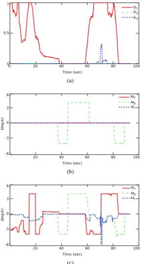
In a first experiment (see Fig. 9a), the robot is maintained on the phantom and tele-operated by the medical expert (Fig. 10) without using the visibility assistance control law (13) but directly the control velocity vector ωm provided by tele-operation. The trajectory of the section gravity center is displayed in green when no visibility constraints are detected, in blue until at least one constraint is involved, and in white when the features leave the visibility region. We can see that white parts of the trajectory appear in Fig. 10a meaning that xg leaves the visibility region defined in the image. However, Fig. 10b shows that using our visibility assistance control law prevents the anatomical object from leaving the image: the trajectory does not pass the red lines. In addition, the weights that behave as visual feature activators (Fig. 11a) are increasing when the medical expert tele-operates the robot each time their relating visual features leave their safe interval. Notice that the weight hxis immediately activated from time
0 to 40 s since the initial section (yellow contour) is already on the limit of the safe image when the medical expert indicates the section of interest before starting the visibility assistance mode. One can see that, from 60 to 80 s, the weights hx and hd are acting to preserve xg in the safe image region and to maintain the current section area d to a minimal value in order to keep the intersection between the object and the US plane. Fig. 11b and 11c show respectively the input velocity ωmprovided by the medical expert via tele-operation and the final velocity resulted from (13) applied to the robot low-level controller.
(a)
(b)
(c)
Fig. 11. Phantom experiment with PROSIT robot: (a) visual feature weights, (b) operated velocity ωm, (c) actual probe velocity
We also performed an experiment in real condition by positioning the robot on the abdomen of a human volunteer. In fact, as we mentioned in Sect. III, the visibility of the section of interest can also be lost due to patient physiological motions (e.g. breathing). Fig. 12a shows the results obtained when an artery section in the liver is selected to be automatically kept in the safe image region with a minimal area. Here, we purposely positioned the US probe to initially observe the artery (yellow contour) at a location close to the border of the safe image area and we did not apply tele-operation velocity ωmin order to see the behavior of our visibility control (13) for patient motion. As expected the visual servoing is automatically triggered thanks to the varying weights (Fig. 12b) to maintain the visual
features inside their safe intervals and the trajectory of the section center never crosses the red line limits. This result demonstrates that the visibility assistance task could be useful to compensate the human physiological motions.
(a) (b)
Fig. 12. Results with human experiments: (a) US image and (b) visual feature weights
V. CONCLUSION
This paper presents a robotized tele-echography system that offers sonographers a solution to perform in real-time a diag-nosis on remotely located patients. To enhance these robotized systems in terms of diagnosis capabilities, we have proposed new assistance tools referred to as autonomous modes. Espe-cially, a visibility assistance task that automatically maintains the visibility of an organ of interest (OI) during a robotized tele-echography act is designed. The main advantage of the proposed shared visual servoing control law is that the medical expert can explore an OI by tele-operating the robot without caring whether it leaves the US image or its intersection with the image plane disappears. Experimental results obtained with a phantom and a human volunteer validated the concept of the control strategy. Furthermore, the visibility assistance also helps to compensate human physiological movements during the diagnosis assessment. In future works, clinical trials will be performed to appreciate the relevance of this robotized assistance mode during tele-echography examinations in order to deliver equitable healthcare in medically isolated settings.
ACKNOWLEDGMENT
This work is supported by the ANR-PROSIT project of the French National Research Agency (ANR-08-CORD-017) and the S2E2 cluster.
REFERENCES
[1] F. Courreges, P. Vieyres, R. S. Istepanian, P. Arbeille, and C. Bru, “Clinical trials and evaluation of a mobile, robotic tele-ultrasound system,” Journal of telemedicine and telecare, vol. 11, no. suppl 1, pp. 46–49, 2005.
[2] P. Arbeille, J. Ayoub, V. Kieffer, P. Ruiz, B. Combes, A. Coitrieux, P. Herve, S. Garnier, B. Leportz, E. Lefbvre, and F. Perrotin, “Realtime tele-operated abdominal and fetal echography in 4 medical centres, from one expert center, using a robotic arm & ISDN or satellite link,” in IEEE
Int. Conf. on Automat., Qual. and Testing, Robot. (AQTR), vol. 1, 2008, pp. 45–46.
[3] F. Bruy`ere, J. Ayoub, and P. Arbeille, “Use of a telerobotic arm to perform ultrasound guidance during renal biopsy in transplant recipients: A preliminary study,” Journal of Endourology, vol. 25, no. 2, pp. 231– 234, 2011.
[4] W. J. Chimiak, R. O. Rainer, N. T. Wolfman, and W. Covitz, “Architec-ture for a high-performance tele-ultrasound system,” in Medi. Imaging:
PACS Design and Evaluation: Eng. and Clinical Issue, R. G. Jost and S. J. D. III, Eds., vol. 2711. SPIE, 1996, pp. 459–465.
[5] G. Kontaxakis, S. Walter, and G. Sakas, “EU-TeleInViVo: an integrated portable telemedicine workstation featuring acquisition, processing and transmission over low-bandwidth lines of 3D ultrasound volume im-ages,” in IEEE EMBS Int. Conf. on Inf. Tech. Appli. in Bio.Med., 2000, pp. 158–163.
[6] P. Abolmaesumi, S. Salcudean, W.-H. Zhu, M. Sirouspour, and S. Di-Maio, “Image-guided control of a robot for medical ultrasound,” IEEE
Trans. Robot. Automat., vol. 18, no. 1, pp. 11–23, 2002.
[7] K. Masuda, E. Kimura, N. Tateishi, and K. Ishihara, “Three dimensional motion mechanism of ultrasound probe and its application for tele-echography system,” in IEEE/RSJ Int. Conf. on Intel. Rob. and Syst.
(IROS), vol. 2, 2001, pp. 1112–1116.
[8] A. Vilchis, J. Troccaz, P. Cinquin, K. Masuda, and F. Pellissier, “A new robot architecture for tele-echography,” IEEE Trans. Robot. Automat., vol. 19, no. 5, pp. 922–926, 2003.
[9] E. Micheli-Tzanakou, P. Vieyres, G. Poisson, F. Courr`eges, N. Smith-Guerin, C. Novales, and P. Arbeille, “A Tele-Operated Robotic Sys-tem for Mobile Tele-Echography: The Otelo Project,” in M-Health, ser. Topics in Bio.Med. Eng. Int. Book Series, R. S. H. Istepanian, S. Laxminarayan, and C. S. Pattichis, Eds. Springer US, 2006, pp. 461–473.
[10] Z. Neubach and M. Shoham, “Ultrasound-Guided Robot for Flexible Needle Steering,” IEEE Trans. Biomed. Eng., vol. 57, no. 4, pp. 799– 805, 2010.
[11] F. Najafi and N. Sepehri, “A novel hand-controller for remote ultrasound imaging,” Mechatronics, vol. 18, no. 10, pp. 578–590, 2008.
[12] T. Essomba, M. A. Laribi, J.-P. Gazeau, S. Zeghloul, and G. Poisson, “Contribution to the Design of a Robotized Tele-Ultrasound System,” in IFToMM Int. Symp. on Robotics and Mechatronics (ISRM), Shangai, Chine, 2011.
[13] L. Nouaille, N. Smith-Guerin, and G. Poisson, “Modeling and geomet-rical validation of a tele-echography robot,” in IEEE/RSJ Int. Conf. on
Intel. Rob. and Syst. (IROS), 2008, pp. 1447–1452.
[14] K. Ito, S. Sugano, and H. Iwata, “Portable and attachable tele-echography robot system: FASTele,” in IEEE Int. Conf. on Eng. in Med.
and Bio. Soc. (EMBC), 2010, pp. 487–490.
[15] L. Nouaille, N. Smith-Guerin, G. Poisson, and P. Arbeille, “Optimization of a 4-DOF tele-echography robot,” in IEEE/RSJ Int. Conf. on Intel. Rob.
and Syst. (IROS), 2010, pp. 3501–3506.
[16] R. Passama and D. Andreu, “ContrACT: a software environment for developing control architecture.” in 6th National Conf. on Contr. Archit.
of Robots. Grenoble, France: INRIA Grenoble Rhˆone-Alpes, May 2011, p. 16 p.
[17] R. Passama, D. Andreu, B. Brun et al., “Upgrading the contract sched-uler with useful mechanisms for dependability of real-time systems,” in 7th National Conf. on Contr. Archit. of Robots, Nancy, France, May 2012.
[18] P. Vieyres, L. Josserand, M. Chiccoli, J. Sandoval, N. Morette, C. No-vales, A. Fonte, S. Avgousti, S. Voskarides, and T. Kasparis, “A predic-tive control approach and interacpredic-tive gui to enhance distal environment rendering during robotized tele-echography: Interactive platform for robotized telechography,” in IEEE 12th Int. Conf. on Bioinformatics &
Bioengineering (BIBE), 2012, pp. 233–239.
[19] F. Chaumette and S. Hutchinson, “Visual servo control, part I: Basic approaches,” IEEE Robot. Automat. Mag., vol. 13, no. 4, pp. 82–90, Dec. 2006.
[20] R. Mebarki, A. Krupa, and F. Chaumette, “2d ultrasound probe complete guidance by visual servoing using image moments,” IEEE Trans. Robot., vol. 26, no. 2, pp. 296–306, 2010.
[21] M. Kass, A. Witkin, and D. Terzopoulos, “Snakes: Active contour models,” Int. J. of Computer Vision, vol. 1, pp. 321–331, 1988. [22] T. Li, A. Krupa, and C. Collewet, “A robust parametric active contour
based on fourier descriptors,” in IEEE Int. Conf. on Image Processing
(ICIP), Brussels, Belgium, 2011.
[23] O. Kermorgant and F. Chaumette, “Combining IBVS and PBVS to ensure the visibility constraint,” in IEEE/RSJ Int. Conf. on Intel. Rob.
and Syst. (IROS), 2011, pp. 2849–2854.
[24] T. Li, O. Kermorgant, and A. Krupa, “Maintaining visibility constraints during tele-echography with ultrasound visual servoing,” in IEEE Int.
Conf. on Intel. Rob. and Automation (ICRA), Saint Paul, USA, May 2012, pp. 4856–4861.
[25] N. Mansard, A. Remazeilles, and F. Chaumette, “Continuity of varying-feature-set control laws,” IEEE Trans. Automat. Contr., vol. 54, no. 11, pp. 2493–2505, Dec. 2009.
[26] N. Mansard, O. Khatib, and A. Kheddar, “A unified approach to integrate unilateral constraints in the stack of tasks,” IEEE Trans. Robot., vol. 25, no. 3, pp. 670–685, 2009.
[27] C. Samson, B. Espiau, and M. L. Borgne, Robot control: the task
function approach. Oxford University Press, 1991.
[28] C. Nadeau and A. Krupa, “Intensity-based direct visual servoing of an ultrasound probe,” in IEEE Int. Conf. on Intel. Rob. and Automation
(ICRA), May 2011, pp. 5677 –5682.
[29] P. Moreira, C. Liu, N. Zemiti, and P. Poignet, “Soft tissue force control using active observers and viscoelastic interaction model,” in IEEE Int.
Conf. on Intel. Rob. and Automation (ICRA), 2012, pp. 4660–4666.
Alexandre Krupa Alexandre Krupa received the M.S. and Ph.D. degrees in control systems and signal processing from the National Polytechnic Institute of Lorraine, Nancy, France, in 1999 and 2003, respectively. He received the ”Habilitation `a Diriger des Recherches” in Signal processing from the University of Rennes, France, in 2012.
His Ph.D. research work was carried out with the eAVR team (Control Vision and Robotics) with the Laboratoire des Sciences de l’Image de l’Informatique et de la T´el´ed´etection, Strasbourg, France. From 2002 to 2004, he was an Assistant Associate Professor for undergraduate student lectures in electronics, control, and computer program-ming with Strasbourg University, Strasbourg, France. Since 2004, he has been a Research Scientist with Inria Rennes - Bretagne Atlantique, France, where he is currently a member of the Lagadic group. In 2006, he was a Postdoctoral Associate with the Computer Integrated Surgical Systems and Technology Engineering Research Center, Johns Hopkins University, Baltimore, MD. His current research interests include medical robotics, computer-assisted systems in the medical and surgical fields, and, most specifically, the control of medical robots by visual servoing using ultrasound images.
David Folio (S’04-A’08-M’11) received his Ph.D. in robotics and control in 2007. His works were held in the Robotics, Action, and Perception (RAP) group of the Laboratory for Analysis and Architecture of Systems (LAAS) under the supervision of Dr. Viviane Cadenat, associate professor at Paul Sabatier university.
He has worked on the design of visual servoing strategies able to tolerate the visual data loss during the execution of a vision-based navigation mission. Between 2007 and 2008, he then joined the Lagadic team from Inria Rennes-Bretagne Atlantique center as a post-doctoral fellow. Since 2008, he is associate professor at the INSA Centre Val de Loire where he is teaching electronics and electrical science. He is working in the Robotic Team of the laboratory PRISME on modeling, control and navigation for micro/nano-robotics and telerobotics fields, mainly devoted to health and biomedical applications.
Pierre Vieyres Pierre Vieyres received a MSC in Electrical engineering from University College Lon-don (UK), and a Ph.D. degree in 1990 in biomedical engineering from the University of Tours (France).
In 1992, he joined the University of Orleans (France), he is currently a full time Professor in the Robotic Team of the laboratory PRISME. Since 1995, he has been involved in the development of robots for the medical field and especially for tele-echography. He was recently the coordinator of the national PROSIT project on robotized tele-echography (2009-2013). His activities focus on the development of haptic systems and bilateral control architecture for tele-operated robots.
Cyril Novales Cyril Novales received the Ph.D. degree in robotics from the University of Montpellier, France, in the CNRS Laboratory LIRMM.
He spent two years as postdoctorate in INRIA Laboratory, Grenoble, working in autonomous vehicles. In 1998, he joined the University of Orleans (France), he is currently an Associate Professor in the Robotic Team of the laboratory PRISME. Since 1998, he was involved in research including autonomous mobile robots and teleoperated robotics dedicated to healthcare.
Tao Li Tao Li received a MSC in Electronics and Computer Engineering from INSA Rennes in 2009, and a Ph.D. degree in robotics in 2013.