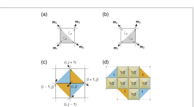
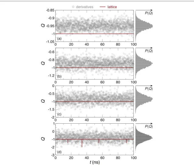
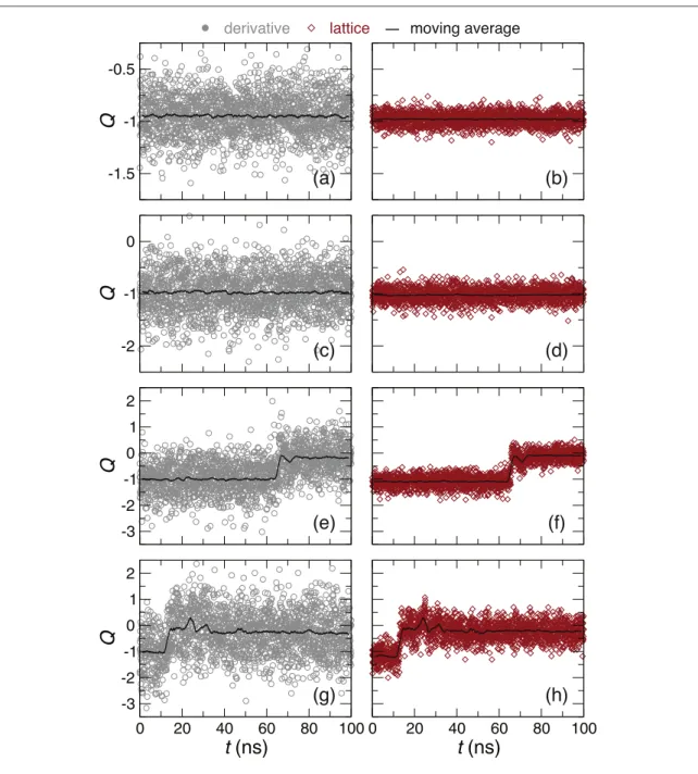
On quantifying the topological charge in micromagnetics using a lattice-based approach
Texte intégral
Figure

Documents relatifs
61 See Supplemental Material for additional electron diffraction images, crystallographic details inferred from single-crystal X-ray diffraction, additional images of
- We present recent studies of the effects of cation substitution on the Charge Density Wave (CDW) transition in VSe,. In order to make a n orderly comparison, some
Les cols sont des regions a faible vitesse de Fermi, et B forte densite d'etats, qui peuvent tenir lieu de puits de diffusion dans la phase haute temperature ;
L’archive ouverte pluridisciplinaire HAL, est destinée au dépôt et à la diffusion de documents scientifiques de niveau recherche, publiés ou non, émanant des
On the origin of a strong central peak in the local density of d states at the surface of transition
Results were presented in the form of graphs that be can directly used to measure local fracture parameters with tests on axisymmetrically notched specimens or to predict
Moreover we make a couple of small changes to their arguments at, we think, clarify the ideas involved (and even improve the bounds little).. If we partition the unit interval for
Complète la colonne qui représente le nombre de candidats admis pour les trois écolesa. Nombres et
