Conductive Filler Morphology Effect on Performance of
Ionic Polymer Conductive Network Composite Actuators
The MIT Faculty has made this article openly available.
Please share
how this access benefits you. Your story matters.
Citation
Liu, Sheng et al. “Conductive filler morphology effect on
performance of ionic polymer conductive network composite
actuators.” Electroactive Polymer Actuators and Devices (EAPAD)
2010. Ed. Yoseph Bar-Cohen. San Diego, CA, USA: SPIE, 2010.
764219-10. Web.
As Published
http://dx.doi.org/10.1117/12.847619
Publisher
SPIE
Version
Final published version
Citable link
http://hdl.handle.net/1721.1/58549
Terms of Use
Article is made available in accordance with the publisher's
policy and may be subject to US copyright law. Please refer to the
publisher's site for terms of use.
Conductive filler morphology effect on performance of ionic polymer
conductive network composite actuators
Sheng Liu
a, Yang Liu
a, Hulya Cebeci
b, Roberto Guzman de Villoria
b, Jun-Hong Lin
c, Brian L.
Wardle
band Qiming Zhang
*a,ca
Department of Electric Engineering, The Pennsylvania State University,
University Park, PA USA 16802
b
Departments of Aeronautics and Astronautics, Massachusetts Institute of Technology,
77 Massachusetts Avenue, Cambridge, MA USA 02139
c
Department of Materials Science and Engineering, The Pennsylvania State University,
University Park, PA USA 16802
ABSTRACT
Several generations of ionic polymer metal composite (IPMC) actuators have been developed since 1992. It has been discovered that the composite electrodes which are composed of electronic and ionic conductors, have great impact on performance of ionic polymer actuators by affecting strain level, efficiency and speed. One of important factors in composite electrodes is the shape and morphology of electronic conductor fillers. In this paper, RuO2 nanoparticles and vertically aligned carbon nanotube (Va-CNT) are used as conductor fillers. Making use of unique properties of Va-CNT forests with ultrahigh volume fraction in Nafion nanocomposite, an ionic polymer actuator is developed. Ion transport speed is greatly increased along CNT alignment direction. The high elastic anisotropy, arising from the high modulus and volume fraction of Va-CNTs, enhances actuation strain while reducing the undesirable direction strain. More than 8% actuation strain under 4 volts with less than one second response time has been achieved.
Keywords: aligned carbon nanotubes, ionic polymer actuators, strain and speed, nanocomposite.
1. INTRODUCTION
1.1 Shapes of electronic conductors
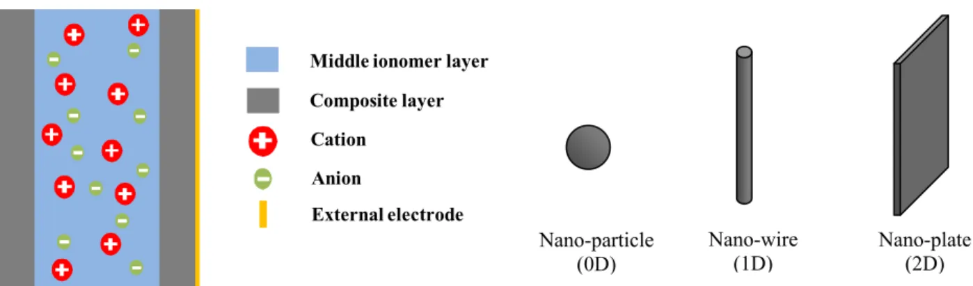
The composite electrodes of ionic devices such as batteries, ultracapacitors, fuel cells and ionic actuators, are composed of electronic and ionic conductors.[1-3] Usually in these devices two composite electrodes are separated a spacer for electron insulation, shown in figure 1. Due to the large volume of carriers— the ions moving inside, the morphology of these electrodes plays an important role in determining device performance. Changing the conductive filler shape is one of the methods of tuning morphology, which could include particles, tubes and plates (shown in fig. 1). In this paper, the effects of different shapes of electronic conductor fillers on device performance are investigated in ionic polymer conductor network composite (IPCNC) actuators (fig. 1). Since 1992, the composite electrodes have been improved in ionic polymer metal composite (IPMC) actuators.[4] The first few generations are fabricated using chemical reduction method to form porous metal layers on Nafion surfaces.[5-7] Then Leo’s group developed direct assembly method using RuO2/Nafion mixture as composite electrodes.[8, 9] Recently self-assembly layer-by-layer (LbL) method has been
developed to coat ultra-thin (sub-micron) composite electrode on Nafion surfaces.[10] All these developments are based on random structures of particle shaped (0D) electronic conductors. The 1D shaped electronic conductors are also used, such as random carbon nanotubes which are easy to reach percolation threshold.[11] 2D shaped conductors such as grapheme and exfoliated graphite nano-plateletshave been developed with great promise to introduce unique properties of composite electrodes, but the application in ionic polymer actuators will be investigated in future.[12, 13] In this paper, we focus on comparing performance of IPCNC with random RuO2 nanoparticles and vertically aligned carbon
nanotubes (Va-CNTs).
* QXZ1@psu.edu; phone 1 814 863 8994; fax 1 814 863 7846
Electroactive Polymer Actuators and Devices (EAPAD) 2010, edited by Yoseph Bar-Cohen, Proc. of SPIE Vol. 7642, 764219 · © 2010 SPIE · CCC code: 0277-786X/10/$18 · doi: 10.1117/12.847619
Middle ionomer layer Composite layer Cation
Anion
External electrode
1.2 Va-CNTs as electronic conductors in ionic polymer actuators
Figure 1. Schematic drawing of general structure of ionic devices such as batteries, ultracapacitors, fuel cells and actuators, with three different shapes of electronic conductors in composite electrodes.
Recent advances in fabricating millimeter size Va-CNT forests with ultrahigh volume fraction (>20 vol% of CNTs) create unique opportunities for developing high performance functional nanocomposites.[1, 14, 15] One area that the high volume fraction Va-CNTs will have impact is the electroactive polymer (EAP) actuators.[3] CNTs have been investigated in the past for standalone EAP actuators and for integrating with other EAPs to form nanocomposites with the aim of enhancing the EAP actuator performance.[3, 11, 16-20] In this paper, we investigate high volume fraction Va-CNTs/ionomer nanocomposites for EAP actuators in which the accumulation or depletion of excess ions at the CNT electrodes generates large strain under a few volts. As will be shown in the paper, the vertical alignment of the CNTs in the electrodes greatly facilitates the ion transport in the porous electrodes and consequently results in a faster actuation speed. The combination of Va-CNTs with high volume fraction (~10 vol%) in the nanocomposites and high elastic modulus of CNTs along the nanotube axis also creates actuators with large elastic anisotropy,[21] which as will be presented in the paper, enhances the actuation strain and consequently improves the efficiency.
Figure2. (a) Schematic of a CNC/ionomer/CNC three layers bimorph actuator with Va-CNTs in the CNC layers (no voltage applied) (b) Schematic of a bended actuator with excess ions on cathode side with voltage applied. z axis is in the thickness direction and x axis along length direction (actuation). In the actuator, the mobile ions are assumed to be cations. Au films (yellow colored layers) are also shown.
Illustrated in figure 2(a) is a schematic of the composite actuator investigated in this paper. The EAP actuator has a three layer structure, consisting of Va-CNTs/ionomer nanocomposite electrode (referred to as the conductor network nanocomposite, CNC, in this paper) layers attached to an ionomer layer, acting as a spacer. To generate large bending actuation, the actuators absorb room temperature ionic liquids (ILs), which provide high concentration of mobile ions and also function as solvent to enhance the ion mobility.[22, 23] Under the application of a voltage, the accumulation of
Nano-particle (0D) Nano-wire (1D) Nano-plate (2D)
excess ions at one electrode (CNC) and depletion at the other electrode (CNC) create differential volume strains in the two regions and cause bending actuation as shown in figure 2(b) in which cations are assumed to be the mobile ions. For this type of actuators, a high concentration of these excess ions in the electrode regions is necessary in order to generate high strain and large force in the EAP actuators. Hence a high volume fraction of Va-CNTs in the ionomer matrix is highly desirable since it will provide a large specific electrode surface area in the CNCs for the storage of these excess ions. This consideration is very similar to that in designing supercapacitors where a large specific electrode surface area is required.[24]
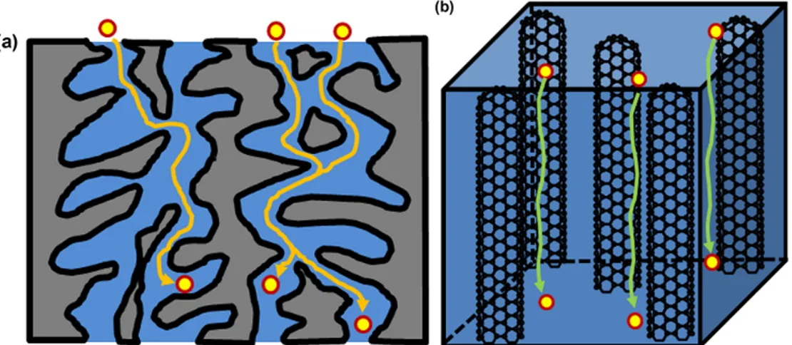
The actuation principle for the EAP actuator investigated here is analogous to that of ionic polymer-metal composite (IPMC) actuators which have been investigated since early 1990s.[4-7, 25, 26] However, there is fundamental difference in the electrode morphology in the Va-CNT/ionomer nanocomposites in this paper and the composite electrodes developed in the early studies of IPMC actuators. For example, one widely investigated IPMCs uses a chemical reduction method to deposit noble metals to ionomer membrane surfaces,[4-6, 25, 26] such as Nafion which a perfluoro-sulfanated ionomer membrane developed by DuPont, in which process nanosized metal particles penetrate into ionomer membrane to form porous electrodes. The electrodes thus formed have tortuous transport paths for the ions to move in and out of the porous electrode regions, as schematically illustrated in figure 3(a). More recently, direct assembly methods were developed in which various types of conductor nanoparticle/ionomer nanocomposite electrode layers were directly deposited on an ionomer substrate to form IPMC bending actuators.[18, 23] Although the direct assembly methods significantly simplify the IPMC fabrication process and also allow for a broad range of conductor nanoparticles, including carbon nanotubes ,[18] to be utilized in CNCs, the random arrangements of the conductor nanoparticles in the CNCs also cause tortuous transport paths for the mobile ions, as has been illustrated in figure 3(a). Moreover, in these randomly mixed nanocomposites, the imperfect contacts between conductor nanoparticles incur large electric resistance. All of these will reduce the ion transport speed in CNC layers under an applied voltage and reduces the actuator efficiency. In contrast, the Va-CNTs based CNCs, as schematically illustrated in figure 3(b), form nearly straight transport pathways for the mobile ions to move into and out of the CNCs.[24] Hence, much short ion transport path and much reduced ion transport resistance in the Va-CNTs based CNCs will cause much fast IPMC actuation speed. Moreover, the reduced electrical resistive loss will also lead to improvement in the actuator efficiency.
Figure 3. (a) Schematic drawing of tortuous ion transport paths in nanoparticle/Nafion CNCs. (b) schematic drawing of nearly straight ion transport paths in Va-CNT/Nafion CNCs.
Besides the electrical considerations, the high volume fraction Va-CNTs based CNCs can also lead to high elastic anisotropy, which is also highly desirable for the bending actuators developed in this paper. The high elastic modulus along with the high volume fraction of the Va-CNTs will create high effective elastic modulus for the composite along the aligned direction of CNTs compared with that in perpendicular direction.[21] As a result, the strain generated in the bending actuators due to the accumulation or depletion of the excess ions in the electric double layers (EDL) in the CNCs will be predominantly along the directions perpendicular to the CNT alignment direction. Since the volume strain generated by excess ions is Sv= Sx + Sy + Sz (see figure 2(b) for the coordinate system) a smaller Sz will increase the
strain level Sx for the actuation, improving the actuation efficiency. In contrast, if the CNCs possess isotropic elastic
along the z-direction (see figure 2) does not contribute to the actuation of the bending actuators which lowers the actuator efficiency. In future, the 2D electronic conductor will be investigated. It is expected that the strain in y-direction strain will be further clamped and electromechanical efficiency will be even larger.
2. EXPERIMENTS
2.1 CNT fabrication
VA-CNTs were grown using a modified chemical vapor deposition (CVD) method on silicon substrates using an Fe on alumina catalyst system. [27, 28] The resulting aligned CNTs have been characterized previously for alignment, CNT diameter, distribution, and spacing. [29] The as-synthesized CNTs (referred to as 1 % volume fraction (Vf)) have
densities of 109–1010 CNTs/cm2. The average diameter of these CNTs is 8 nm and the CNT-CNT spacing (center to
center) is approximately 80 nm. For high volume fraction CNT fabrication, the released array is then subjected to mechanical biaxial compression in two orthogonal directions. By varying the intertube distance via compression, variable-density CNT arrays are obtained. [15] In addition, the alignment of CNTs and uniformity of CNT density are still preserved.
2.2 CNT/Nafion composite fabrication
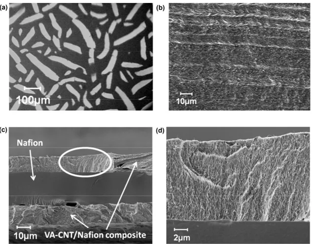
In order to take full advantages of the high volume fraction Va-CNTs/ionomer nanocomposites for the intended EAP actuators, the nanocomposites must be fabricated free of voids, which requires careful design of fabrication process to avoid the formation of voids in the CNC composites during the evaporation of the solvent. In this study, 10 vol% Va-CNT forests were used in order to create relatively large sized actuators. Nafion was selected for the ionomer matrix because of high ionic conductivity and desired mechanical properties.[30, 31] In the fabrication process of the Va-CNT forste/Nafion composites, the solvent in alcohol based commercial Nafion dispersion purchased from Ion-Power® was replaced by Dimethylformamide (DMF) so that the solvent can be evaporated at a very slow rate. A fast evaporation of the solvent will cause collapse of CNT array and cracks inside composite (see figure 4(a)). The high boiling point (153°C) of DMF makes it possible to slowly evaporate the solvent when processed at room temperature. In the fabrication process, the Nafion solution is infiltrated into CNT arrays under vacuum for several hours to remove trapped air between nanotubes, which is extremely important in order to prepare high quality Va-CNTs/Nafion composites. The whole evaporation process usually takes about one week. After removing the solvent, the composite is annealed at 130°C under vacuum for 1 h to increase crystallinity of Nafion.
The typical dimension of Va-CNTs/Nafion composites fabricated is 3 mm × 5 mm in the lateral direction and several millimeters thick. In order to fabricate CNCs for the intended bimorph actuators in figure 2, CNC layer thickness should be much smaller than the length (x-direction) as well as width (y-direction, which should be smaller than the length). A microtome was employed to cut the composites into thin thickness for CNC layers to be used in the actuators of figure 2 so that the bending actuation under applied voltages can be easily observed and characterized.[32] In this fabrication process, the fabricated Va-CNTs/Nafion nanocomposites were embedded in an epoxy before being sectioned. After epoxy cured, the samples were mounted on a Finesse microtome with Va-CNTs perpendicular to the cutting direction. The thin slices contained extra epoxy surrounding Va-CNTs/Nafion nanocomposites which were removed by carefully cutting along the edges with a razor blade. SEM image has been taken and shown in figure 4(b) in through plane direction, displaying CNT tips out of the composite slices.
2.3 Actuator fabrication
The actuators investigated in this paper have final CNC layer thickness of 12 μm on a 25 μm Nafion film (commercial Nafion NR-211) and hence the total thickness of the actuator is 49 μm. The CNC layer was bonded to the Nafion film by an ultra-thin layer of Nafion dispersion (<0.1µm), which was deposited on the neat Nafion films by ultrasonic spraying. CNC layers were laminated on the neat Nafion films with thin Nafion dispersion and the whole CNC/Nafion/CNC layers were then clamped by two pieces of Kapton films under a pressure. The stacks were dried and then annealed at 130 oC to further improve the bonding . A SEM image of the cross section of the finished actuators is
shown in figure 4(c). The interface between CNC and Nafion films is amplified and shown in figure 4(d), displaying aligned CNTs in the CNC layers.
Figure 4. (a) Optical image of CNT/Nafion collapse due to fast solvent evaporation. (b) SEM image of good quality Va-CNT/Nafion composite surface with CNT array in through plane direction. The white tiny dots indicates Va-CNT tips. (c) SEM image showing cross-section of fabricated Va-CNT actuators. (d) SEM image of interface region (white circle in (c)) showing aligned CNT in CNC layer.
3. RESULTS AND DISCUSSIONS
3.1 Anisotropic mechanical property
The anisotropic strain generation property of the high volume fraction (10 vol%) Va-CNTs/Nafion nanocomposite was demonstrated by testing the strains generated along and perpendicular to the CNT alignment direction (i.e., the thickness direction or z-direction) of Va-CNTs/Nafion composites from the absorption of ILs. For the comparison, pure Nafion films were also fabricated under the same condition and the strains were also characterized along and perpendicular to the thickness direction due to the absorption of ILs. Here the imidazolium based IL, 1-ethyl-3-methylimidazolium trifluoromethanesulfonate (EMI-Tf), was chosen for the study. Imidazolium ionic liquids (ILs) have been investigated very extensively as the electrolytes for ionic EAP actuators.[22, 23] It has been shown that due to the negligible vapor pressure, the utilization of ILs as the electrolytes for IPMC actuators enables the IPMC actuators to be operated in air for very long operation life (>106 actuation cycles).[23] Furthermore, the high electrochemical window and high ion
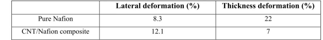
mobility can also lead to improved ionic EAP actuator performance.[18, 22, 23] Among various imidazolium based ILs, earlier studies have shown that the ionic EAP actuators with EMI-Tf display high actuation strain and fast actuation speed.[18, 23] After soaking IL, the CNCs filled with Va-CNTs exhibit a different anisotropic deformation from neat Nafion films fabricated using the same solution cast method, as shown in table 1. The pure Nafion films, upon absorption of 35 wt% of EMI-Tf, exhibit a large thickness strain Sz=Δl/l0~22%, where l0 is the original thickness and Δl
is the thickness change, and a much smaller lateral strain (perpendicular to the thickness direction, = 8.3%). In addition, a commercial Nafion film (Nafion NR211, fabricated from solution cast by DuPont) was also studied and very similar results were obtained. In contrast, the Va-CNTs/Nafion nanocomposite films exhibit much smaller Sz (=7%) while the
lateral strain is increased to 12.1%. These results demonstrate that the high volume fraction Va-CNTs can markedly reduce the strain in the composites along its alignment direction while enhancing the strain in the perpendicular direction, as desired for the actuators developed here.
Table 1. Mechanical deformation of pure Nafion and CNT/Nafion composite with same amount IL uptake.
Lateral deformation (%) Thickness deformation (%)
Pure Nafion 8.3 22
CNT/Nafion composite 12.1 7
3.2 Strain
Presented in figure 5(a) is the bending actuation generated for the actuator of figure 1 with length (x-direction) of 5mm and width (y-direction) of 0.8 mm, from which the bending actuation radius of curvature is deduced (R=1.83mm). In the bending actuator fabricated, Au films of 50 nm thick were bonded to the Va-CNT/Nafion composite as shown in figure 1(b). Au films were used here to ensure high electrical conductivity along the actuator surface so that there is very little voltage drop along the film surface (the electrical conductivity of Va-CNTs/Nafion composite in perpendicular to the CNT alignment direction is low).
In these actuators, the bending actuation is generated by the strains in the CNC layers. In order to extract the strain in the CNC layer, we use the relationship between the bending radius of curvature R and the strain
S
10c along the film surface in the CNC layers derived in an early publication.24 It should be noted that In the bending actuators, the actualstrain
S
1c is reduced fromS
10c due to the stresses from the ionomer layer and Au film, i.e.,
S
1c=
S
10c+
s
11cT
1c (1) where sc11 is the elastic compliance and Tc1 is the stress along the film surface.
S
10c can be deduced from the radius ofcurvature, the thickness and elastic modulus of each layer.[10] In order to derive
S
10c , the elastic modulus of Va-CNTs/Nafion composite absorbed with EMI-Tf was determined. From the radius of curvature along with the elastic modulus data for each layer in the actuator of figure 1,S
10c was deduced to be 8.2% under 4 volts applied voltage. The actuator speed was also characterized by measuring the response of the actuator under a step voltage of 4 volts and the data is presented in figure 5(b). The data is fitted well with an exponential function,
⎟⎟
⎠
⎞
⎜⎜
⎝
⎛
−
−
=
0 0 10 10(
)
/
1
exp
τ
t
S
t
S
c c (2)The fitting results from several 10 vol% Va-CNTs/Nafion based bending actuators yield a τ0= 0.82 ± 0.09 seconds. In
comparison, the bimorph bending actuators with RuO2 nanoparticle/Nafion CNCs on the same Nafion film (Nafion
NR-211) show a τ0 =1.03 seconds for actuators with CNC layer thickness of 3 μm and hence the total actuator thickness of
31 μm.[10] RuO2/Nafion nanocomposite ionic polymer conductor network composites have been investigated extensively and have shown high strain response (~2.4% strain) among the IPMCs developed.[4-6, 8, 18, 25, 26, 33] As has been observed in early experiments, the actuator response time for the bending actuator as shown in figure 1 is dominated by the ion transport time in the CNC layers and a thick CNC layer will lead to larger actuation time (slow actuation speed).[34] For instance, we have shown in reference 24 that by using 0.4 μm thick CNC layer on 25 μm Nafion film (hence the total actuator thickness is 26 μm), the bending actuation time can be reduced to 0.18 seconds for CNCs with randomly arranged conductor nanoparticles in CNCs.[10] The time constants of the three actuators with different CNC type and thickness is plotted in figure 5(c). The reduced actuation time while the CNC layer thickness is increased from 3 μm to 12 μm demonstrates that employing Va-CNTs/ionomer nanocomposites as CNCs can markedly improve the actuation speed of the ionic EAP actuators. This is also indicated by figure 5(d), in which the time constant of each kind of actuator is divided by the thickness of CNC layer. Actuators with Va-CNT/Nafion CNC has the shortest
time constant per unit thickness of 0.068 s/µm, while the actuators with random nanoparticle filled CNCs have relatively large time constant per unit thickness of 0.45 s/µm and 0.34 s/µm for LbL and RuO2/Nafion CNC, respectively. The
large strain and fast actuation time observed in this study indicate the potential of ultra-high volume fraction Va-CNTs for high performance ionic polymer actuators.
Figure 5. (a) Image of a bending Va-CNT/Nafion composite actuator reaching maximum strain (8.2%) under 4 volts. (b) Normalized strain versus time under a step voltage of 4 volts and its fitting curve with exponential function. (c)(d) Comparison of actuation speed among actuators with 0.4µm LbL, 3µm RuO2/Nafion and 12µm Va-CNT/Nafion CNCs from fitting strain versus time with
exponential function under 4 volts: (c) time constants of each actuator, (d) comparison of the time constant per unit CNC thickness for several ionic polymer actuators investigated recently by the authors[10].
3.3 Ionic conductivity
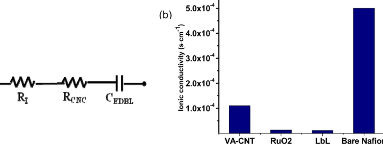
Ionic conductivity is characterized using a Princeton Applied Research® PAR-2273 potentiostat with frequency response
analyzer. The electrical model is simplified, with three components shown in figure 6(a). RI is the real impedance of
Nafion spacer; RCNC is the real impedance of composite electrode; and CEDBL is the electrical double layer capacitance
formed in composite electrodes.
At high frequency, usually 10 kHz for ionic actuators, the capacitors are shorted and total impedance equals to sum of RI
and RCNC The ionic conductivity is calculated using formula
A
R
t
CNC CNC⋅
=
σ
(3) where tCNC is the total thickness of composite electrode and A is the sample size. The results show that bare Nafion hasthe largest ionic conductivity 5×10⁻⁴ S·cm-1. Although LbL shows overall large speed in time domain strain response its
ionic conductivity is the lowest 1.1×10⁻⁵ S·cm-1. Same as random particle structure, RuO
higher value of 1.3×10⁻⁵ S·cm-1. Va-CNT/Nafion, due to its aligned morphology, shows much increase ionic conductivity
among composite electrodes, with 1.1×10⁻⁴ S·cm-1. The results are plotted together in figure 6(b) for comparison.
Figure 6. (a) Simplified electrical model for IPCNC actuators; (b) ionic conductivity of different layers.
4. CONCLUSIONS
In conclusion, we show that by making use of Va-CNTs with high volume fraction in nanocomposites with Nafion, the nanocomposite actuators can suppress the strain generated along the CNT alignment direction, which is not desirable for the actuator and reduces the efficiency, while enhancing the strain along the actuation direction. The vertical alignment of CNTs in the CNCs greatly facilitates the ion transport in the CNCs along the CNT alignment direction, compared with the CNCs with randomly dispersed conductor nanoparticles. The ionic actuators with EMI-Tf IL thus developed exhibit an actuation strain of more than 8% under 4 volts. For the actuators with 12 μm CNC layer thickness of 25 μm Nafion films (total actuator thickness is 49 μm), the actuation response time under a step voltage of 4 volts is about 0.8 seconds. These results demonstrate the potential of high volume fraction Va-CNTs for ionic polymer actuators with high strain and fast response speed. The results also show the importance in tailoring the CNC morphology in these ionic polymer actuators to achieve high performance.
Acknowledgements
This material is based upon work at Penn State University supported in part by the U.S. Army Research Office under Grant No. W911NF-07-1-0452 Ionic Liquids in Electro-Active Devices (ILEAD) MURI. At MIT the work was supported by Airbus S.A.S., Boeing, Embraer, Lockheed Martin, Saab AB, Spirit AeroSystems, Textron Inc., Composite Systems Technology, and TohoTenax Inc. through MIT’s Nano-Engineered Composite aerospace STructures (NECST) Consortium. Hülya Cebeci acknowledges support from Scientific and Technical Research Council of Turkey (TUBITAK) for a 2214-International Research Fellowship Programme. Roberto Guzman de Villoria is grateful for the support of the Ministry of Science and Education (MEC) for the award of a FPU grant (AP-2004-6264).
REFERENCES
[1] D. N. Futaba, K. Hata, T. Yamada, T. Hiraoka, Y. Hayamizu, Y. Kakudate, O. Tanaike, H. Hatori, M. Yumura and S. Iijima, “Shape-engineerable and highly densely packed single-walled carbon nanotubes and their application as super-capacitor electrodes,” Nature Materials, 5(12), 987-994 (2006).
[2] V. Mehta and J. S., “Cooper, Review and analysis of PEM fuel cell design and manufacturing,” J. Power Sources, 114(1), 32-53 (2003).
[3] Y. Bar-Cohen and Q. M. Zhang, “Electroactive polymer actuators and sensors,” MRS Bull., 33(3), 173-181 (2008). [4] K. Oguro, Y. Kawami and H. Takenaka, “Bending of an ion-conducting polymer film-elelctrode composite by and electric stimulus at low voltage,” Journal of Micromachine Society, 5(27), 27-30 (1992)
VA-CNT RuO2 LbL Bare Nafion 1.0x10⁻⁴ 2.0x10⁻⁴ 3.0x10⁻⁴ 4.0x10⁻⁴ 5.0x10⁻⁴ Io n ic co ndu ct iv it y ( s ⋅ cm -1 )
(a)
(b)
[5] M. Shahinpoor, “MICROELECTROMECHANICS OF IONIC POLYMERIC GELS AS ELECTRICALLY CONTROLLABLE ARTIFICIAL MUSCLES,”Journal of Intelligent Material Systems and Structures, 6(3), 307-314 (1995).
[6] M. Shahinpoor, Y. Bar-Cohen, J. O. Simpson and J. Smith, “Ionic polymer-metal composites (IPMCs) as biomimetic sensors, actuators and artificial muscles - a review,” Smart Materials & Structures, 7(6), R15-R30 (1998).
[7] D. Kim, K. J. Kim and Y. Tak, “Self-oscillating electroactive polymer actuator,” Applied Physics Letters, 90(18), 184104 (2007)
[8] B. J. Akle, M. D. Bennett and D. J. Leo, “High-strain ionomeric-ionic liquid electroactive actuators,” Sensors and Actuators a-Physical, 126(1), 173-181 (2006).
[9] B. J. Akle, M. D. Bennett, D. J. Leo, K. B. Wiles and J. E. McGrath, “Direct assembly process: a novel fabrication technique for large strain ionic polymer transducers,” Journal of Materials Science, 42(16), 7031-7041 (2007).
[10] S. Liu, R. Montazami, Y. Liu, V. Jain, M. R. Lin, J. R. Heflin and Q. M. Zhang, “Layer-by-layer self-assembled conductor network composites in ionic polymer metal composite actuators with high strain response,” Applied Physics Letters, 95(2), 023505 (2009)
[11] K. Mukai, K. Asaka, T. Sugino, K. Kiyohora, I. Takeuchi, N. Terasawo, D. N. Futoba, K. Hata, T. Fukushima and T. Aida, “Highly Conductive Sheets from Millimeter-Long Single-Walled Carbon Nanotubes and Ionic Liquids: Application to Fast-Moving, Low-Voltage Electromechanical Actuators Operable in Air,” Advanced Materials, 21(16), 158 (2009).
[12] A. Yoshida, Y. Hishiyama and M. Inagaki, “EXFOLIATED GRAPHITE FROM VARIOUS INTERCALATION COMPOUNDS,” Carbon, 29(8), 1227-1231 (1991).
[13] M. Inagaki and T. Suwa, “Pore structure analysis of exfoliated graphite using image processing of scanning electron micrographs,” Carbon, 39(6), 915-920 (2001).
[14] E. J. Garcia, A. J. Hart, B. L. Wardle and A. H. Slocum, “Fabrication of composite microstructures by capillarity-driven wetting of aligned carbon nanotubes with polymers,” Nanotechnology, 18(16), 165602 (2007)
[15] B. L. Wardle, D. S. Saito, E. J. Garcia, A. J. Hart, R. G. de Villoria and E. A. Verploegen, “Fabrication and characterization of ultrahigh-volume-fraction aligned carbon nanotube-polymer composites,” Advanced Materials, 20(14), 2707 (2008).
[16] R. H. Baughman, C. X. Cui, A. A. Zakhidov, Z. Iqbal, J. N. Barisci, G. M. Spinks, G. G. Wallace, A. Mazzoldi, D. De Rossi, A. G. Rinzler, O. Jaschinski, S. Roth and M. Kertesz, “Carbon nanotube actuators,” Science, 284(5418), 1340-1344 (1999).
[17] G. M. Spinks, V. Mottaghitalab, M. Bahrami-Saniani, P. G. Whitten and G. G. Wallace, “Carbon-nanotube-reinforced polyaniline fibers for high-strength artificial muscles,” Advanced Materials, 18(5), 637 (2006).
[18] B. J. Akle and D. J. Leo, “Single-walled carbon nanotubes - Ionic polymer electroactive hybrid transducers,” Journal of Intelligent Material Systems and Structures, 19(8), 905-915 (2008).
[19] B. J. Landi, R. P. Raffaelle, M. J. Heben, J. L. Alleman, W. VanDerveer and T. Gennett, “Single wall carbon nanotube-Nafion composite actuators,” Nano Letters, 2(11), 1329-1332 (2002).
[20] Y. Yun, V. Shanov, Y. Tu, M. J. Schulz, S. Yarmolenko, S. Neralla, J. Sankar and S. Subramaniam, “A multi-wall carbon nanotube tower electrochemical actuator,” Nano Letters, 6(4), 689-693 (2006).
[21] L. Ci, J. Suhr, V. Pushparaj, X. Zhang and P. M. Ajayan, “Continuous carbon nanotube reinforced composites,” Nano Letters, 8(9), 2762-2766 (2008).
[22] W. Lu, A. G. Fadeev, B. H. Qi, E. Smela, B. R. Mattes, J. Ding, G. M. Spinks, J. Mazurkiewicz, D. Z. Zhou, G. G. Wallace, D. R. MacFarlane, S. A. Forsyth and M. Forsyth, “Use of ionic liquids for pi-conjugated polymer electrochemical devices,” Science, 297(5583), 983-987 (2002).
[23] M. D. Bennett and D. J. Leo, “Ionic liquids as stable solvents for ionic polymer transducers,” Sens. Actuators A, 115(1), 79-90 (2004).
[24] P. Simon and Y. Gogotsi, “Materials for electrochemical capacitors,” Nature Materials, 7(11), 845-854 (2008). [25] J. W. Paquette and K. J. Kim, “Ionomeric electroactive polymer artificial muscle for naval applications,” IEEE Journal of Oceanic Engineering, 29(3), 729-737 (2004).
[26] S. Nemat-Nasser and Y. X. Wu, “Comparative experimental study of ionic polymer-metal composites with different backbone ionomers and in various cation forms,” J. Appl. Phys., 93(9), 5255-5267 (2003).
[27] A. J. Hart and A. H. Slocum, “Rapid growth and flow-mediated nucleation of millimeter-scale aligned carbon nanotube structures from a thin-film catalyst,” J Phys Chem B, 110(16), 8250-8257 (2006).
[28] E. J. Garcia, A. J. Hart and B. L. Wardle, “Long carbon nanotubes grown on the surface of fibers for hybrid composites,” AIAA J, 46(6), 1405-1412 (2008).
[29] A. J. Hart and A. H. Slocum, “Force output, control of film structure, and microscale shape transfer by carbon nanotube growth under mechanical pressure,” Nano Lett, 6(6), 1254-1260 (2006).
[30] K. D. Kreuer, “On the development of proton conducting polymer membranes for hydrogen and methanol fuel cells,” Journal of Membrane Science, 185(1), 29-39 (2001).
[31] K. A. Mauritz and R. B. Moore, “State of understanding of Nafion,” Chemical Reviews, 104(10), 4535-4585 (2004).
[32] Q. B. Xu, R. Perez-Castillejos, Z. F. Li and G. M. Whitesides, “Fabrication of high-aspect-ratio metallic nanostructures using nanoskiving,” Nano Letters, 6(9), 2163-2165 (2006).
[33] J. D. W. Madden, N. A. Vandesteeg, P. A. Anquetil, P. G. A. Madden, A. Takshi, R. Z. Pytel, S. R. Lafontaine, P. A. Wieringa and I. W. Hunter, “Artificial muscle technology: Physical principles and naval prospects,” IEEE J. Oceanic Eng., 29(3), 706-728 (2004).
[34] S. Liu, Y. Liu, M. Lin, X. Zhou, Q.M. Zhang, R. Montazami, V. Jain and J.R. Heflin, “Influence of the conductor network composites on the electromechanical performance of ionic polymer conductor network composite actuators,” Sensor and Actuators Phys. A, 157(2), 267-275 (2010).