HAL Id: hal-01753426
https://hal.archives-ouvertes.fr/hal-01753426
Submitted on 29 Mar 2018
HAL is a multi-disciplinary open access
archive for the deposit and dissemination of
sci-entific research documents, whether they are
pub-lished or not. The documents may come from
teaching and research institutions in France or
abroad, or from public or private research centers.
L’archive ouverte pluridisciplinaire HAL, est
destinée au dépôt et à la diffusion de documents
scientifiques de niveau recherche, publiés ou non,
émanant des établissements d’enseignement et de
recherche français ou étrangers, des laboratoires
publics ou privés.
Architectural optimization of an epoxy-based hybrid
sol–gel coating for the corrosion protection of a cast
Elektron21 magnesium alloy
Noé Verner Murillo-Gutiérrez, Florence Ansart, Jean-Pierre Bonino, S.R.
Kunst, C.F. Malfatti
To cite this version:
Noé Verner Murillo-Gutiérrez, Florence Ansart, Jean-Pierre Bonino, S.R. Kunst, C.F. Malfatti.
Ar-chitectural optimization of an epoxy-based hybrid sol–gel coating for the corrosion protection of a
cast Elektron21 magnesium alloy. Applied Surface Science, Elsevier, 2014, vol. 309, pp. 62-73.
�10.1016/j.apsusc.2014.04.169�. �hal-01753426�
To cite this version : Murillo-Gutiérrez, Noé Verner and Ansart, Florence and
Bonino, Jean-Pierre and Kunst, S.R. and Malfatti, C.F. Architectural
optimization of an epoxy-based hybrid sol–gel coating for the corrosion
protection of a cast Elektron21 magnesium alloy. (2014) Applied Surface
Science, vol. 309. pp. 62-73. ISSN 0169-4332
O
pen
A
rchive
T
OULOUSE
A
rchive
O
uverte (
OATAO
)
OATAO is an open access repository that collects the work of Toulouse researchers and
makes it freely available over the web where possible.
This is an author-deposited version published in :
http://oatao.univ-toulouse.fr/
Eprints ID : 19804
To link to this article :
DOI : 10.1016/j.apsusc.2014.04.169
URL : http://dx.doi.org/10.1016/j.apsusc.2014.04.169
Any correspondence concerning this service should be sent to the repository
administrator:
staff-oatao@listes-diff.inp-toulouse.fr
Architectural optimization of an epoxy-based hybrid sol–gel coating
for the corrosion protection of a cast Elektron21 magnesium alloy
N.V. Murillo-Gutiérrez
a,∗, F. Ansart
a, J-P. Bonino
a, S.R. Kunst
b, C.F. Malfatti
baUniversité de Toulouse UPS-INP-CNRS, Institut Carnot CIRIMAT, Toulouse, France
bUniversidade Federal do Rio grande do Sul, Laboratory of Corrosion Research (LAPEC), Porto Alegre, Brazil
Keywords: Magnesium Corrosion Sol–gel Coating Impedance Elektron21
a b s t r a c t
An epoxy-based hybrid sol–gel coating was prepared in various architectural configurations has been studied for the corrosion protection of a cast Elektron21 magnesium alloy. The creation of a single layer of this coating presents defects consisting of macro-pores and protuberances, which opens access for cor-rosive species to reach the metallic substrate. These defects are suspected to result from the high reactivity of the substrate, as well as to the irregular topography of the substrate disrupted by the microstructure of the own magnesium alloy. Hence, a sol–gel coating in bilayer architecture is proposed, where the first layer would “inert” the surface of the magnesium substrate, and the second layer would cover the defects of the first layer and also thickening the coating. The morphological characteristics of the sol–gel coatings were analyzed by scanning electron microscopy (SEM), and their corrosion behavior was evaluated by OCP (open circuit potential) monitoring and electrochemical impedance spectroscopy (EIS) in chloride media. It is shown that both the architectural arrangement and the individual thickness of the first and second layers have an important influence on the anticorrosion performances of the protective system, just as much as its global thickness.
1. Introduction
The lower density than that of aluminum (around 30% less), makes the magnesium and its alloys an interesting material for the automotive and aeronautics industries, since this structural metal could allow the production of specific pieces and the construction of lighter vehicles. This strategy is related to the reduction of com-bustible consumption of transport vehicles and the optimization of resources. Nonetheless, these alloys are highly susceptible to corrosion when exposed to aggressive environments, resulting on the loss of its mechanical characteristics. In the recent years, many magnesium alloys have been developed in order to increase both its mechanical and corrosion resistance[1–4], but even though it is necessary to apply a protective coating on the metallic surface in order to prevent the contact with corrosive species. Many of the most efficient surface treatments for magnesium alloys uses chromium-based compounds including Cr6+species, highly toxic
and harmful for health and the environment, which are in process of interdiction by the international normative.
∗ Corresponding author. Tel.: +33 5 61 55 78 71.
E-mail addresses:murillo@chimie.ups-tlse.fr,n verner mg@hotmail.com
(N.V. Murillo-Gutiérrez).
This background leads to the research for alternative surface treatments for magnesium alloys excluding the use of danger-ous compounds. The sol–gel route is a chemical way to produce harmless inorganic materials generally by using metallic alcoxydes, which may also contain organic functions (acrylic, vinyl, etc.) per-mitting the production of hybrid organic/inorganic materials and coatings with improved flexibility. In particular, the epoxy-based materials presents interesting characteristics like mechanical resis-tance and good chemical and thermic stability, superior to other types of hybrid materials[5–7]. A number of hybrid coatings have been produced for the corrosion protection of different metallic substrates such as steels[8], aluminum[9]or zinc alloys[10]. In the case of magnesium alloys, many authors have reported the use of this kind of coatings[11–16], showing a considerable degree of protection.
Commonly, the protective coatings applied on the automotive
[17]and aeronautics[18]industries consists of a series of super-posed layers of different chemical nature, which typically consists of a chemical/anodic conversion layer, an adhesion primer and an organic paint or finishing. Many surface treatments for magnesium alloys including a sol–gel coating have been studied in combination with conversion layers[19,20], anodic coatings[21,22]or even mul-tilayered sol–gel coatings[23–25], in order to provide a complex “architecture” to the protective anticorrosion system.
Table 1
Chemical composition of the cast magnesium alloy.
Elektron21
Element Nd Gd Zr Zn Other rare earths Mg Wt.% 3.1 1.7 1.0 0.5 <0.4 Balance
The present work proposes an architectural approach to the production of an epoxy-based sol–gel coating, for the corrosion protection of a cast magnesium alloy (Mg–Nd–Gd–Zr–Zn). Usually, the metallic pieces obtained by low-pressure casting may contain a large amount of impurities at the surface, also presenting a very irregular and rough surface resulting from the contact with the mold. Hence, a chemical etching is generally applied for this kind of pieces in order to remove the contaminated and rough exter-nal layer before the application of protective coatings[26], though this surface pretreatment may expose the microstructure of the metallic substrate. On the other hand, the high reactivity of the magnesium substrate in aqueous media manifests itself when the sol contains a large portion of water, complicating the preparation of homogeneous coatings without pores and defects. Therefore, a bilayer epoxy-based sol–gel system is presented, where the first created sol–gel layer of sol would undergo the chemical reactions with the magnesium alloy, but thereby providing an inert sur-face for a second sol–gel layer which contribute to the thickening of the sol–gel coating. The morphological aspects of the sol–gel systems are analyzed by scanning electron microscopy, and their electrochemical properties are studied by OCP (open circuit poten-tial) monitoring and electrochemical impedance spectroscopy in chloride media (0.05 M NaCl solution), in order to evaluate their corrosion resistance.
2. Experimental 2.1. Materials
2.1.1. Substrate preparation
The substrate consists of a cast Elektron21 (EV31A) magne-sium alloy, provided by Fonderie Messier. After heat treatment (T6 code: heat solution and aging), large ingots of this alloy where cut and machined to obtain smaller coupons with dimensions of 40 × 20 × 6 mm. The composition of this magnesium alloy is pre-sented onTable 1, furnished by the supplier.
After degreasing with acetone, the magnesium samples were polished with a SiC paper up to grade #1200, and subsequently rinsed with ethanol and dried with a stream of air. Then, the samples followed an acid etching with 20 g/L of HNO3 for 2 min,
followed by rinsing with ethanol and drying with a flux of air.
2.1.2. Sols and coatings preparation
The sols where produced by mixture of 3-glycidyloxypropyl-trimethoxysilane (GPTMS), aluminium-tri-sec-butoxide (ASB), deionized water and propanol in a molar ratio of 2:1:1:10. The mix-ture was kept under stirring for 2 h, followed by aging for 24 h at room temperature, before application on the magnesium samples. The viscosity of the sols was around 15 mPa s. The bilayer hybrid sol–gel coatings were obtained by the dip-coating technique, by immerging the magnesium samples into the sols, and withdrawing with a controlled speed of 50, 100, 200 or 400 mm/min, and sub-sequently realizing a heat treatment. The heat treatment includes two steps: drying at 50◦C for 2 h, and curing at 110◦C for 3 h. The
protective coatings were obtained by applying one or two layers of hybrid sol–gel film, where for each layer produced a heat treatment was applied.
2.2. Characterization techniques
Viscosity of the sols was measured before production on the substrates with a Lamy RM-100 rheometer. The morphology of the magnesium substrate and coatings were analyzed by scanning elec-tron microscopy (SEM) with a JEOL JSM-6510LV microscope, using an operating voltage of 20 kV. Electrochemical impedance spec-troscopy (EIS) and open circuit potential (Eocp) monitoring were
performed in a 0.05 M NaCl solution at room temperature, using a NOVA frequency response analyzer and an AUTOLAB PGSTAT 30 potentiostat. The Eocp measurements were performed during
the first hour of immersion of the samples in the corrosive solu-tion. The measurements were performed using a three-electrode cell. The working electrode exposed area was 2 cm2, with a
ref-erence and auxiliary electrodes consisting of a saturated calomel electrode (SCE) and a platinum foil electrode, respectively. The EIS spectra were drawn using a potentiostatic mode in the frequency range from 100 kHz to 10 mHz, with an applied voltage of 10 mV vs. Eocp. The reproducibility of the tests was verified by analyzing
three samples for each characterization technique. 3. Results and discussion
3.1. Magnesium substrate
The surface of the magnesium alloy samples after acid treat-ment is shown onFig. 1a. The microstructure of the alloy shows the magnesium-rich grains, joined by two segregated regions. These regions correspond to neodymium-rich zones (grain boundaries) and to zirconium-rich zones (located inside the magnesium grains).
On Fig. 1a, the irregularity of the surface of the alloy may be
observed, where the zirconium-rich zones seem to be higher than the rest of the surface.Fig. 1b shows a cross-section SEM image of the substrate on back-scattered electrons (BSE) mode, where the presence of a white region (neodymium grain boundary), and a pro-tuberance may be identified. The EDX analysis of the image reveals that the protuberance contains mainly zirconium (Fig. 1c). These zirconium-rich protuberances are supposed to be created due to a lower dissolution rate of the zirconium than that of the magnesium grains and the neodymium-rich zones, during the acid etching. 3.2. Monolayer hybrid coating
3.2.1. Morphological characterization
The surface and the cross-section of the monolayer hybrid coat-ing were observed by SEM (Fig. 2). It may be seen on the surface view of the sample (Fig. 2a) the irregular surface of the hybrid coating, which presents two kinds of defects: protuberances and pits. The cross-section view of the substrate on BSE mode (Fig. 2b) shows the average thickness of the hybrid coating, estimated to 5.2 ± 0.3 mm. As previously shown inFig. 1b, the presence of protu-berances may be observed, created by the zirconium-rich regions. At this location, the thickness of the film is reduced and disrupts the homogeneity of the coating. The second kind of defect, the pits, may be attributed to the reactivity of the alloy with the sol that produces a hydrogen evolution and therefore creating uncovered regions.
3.2.2. Electrochemical measurements
The electrochemical behavior of the bare magnesium alloy, and covered monolayer hybrid coating (M) was analyzed by immersion in a corrosive solution containing 0.05 M of NaCl. The open circuit potential (Eocp) was followed during the first hour of the immersion
(Fig. 3).
From the beginning of the immersion, the Eocp value for the
Fig. 1. SEM image of the cast magnesium alloy after acid etching with 20 g/L of HNO3: (a) surface of the substrate; (b) cross-section (mode BSE); (c) EDX analyze for zirconium.
associated to the development of a passivity layer as a result of the reaction between with the electrolyte. On the other hand, the potential of the substrate coated by the monolayer hybrid film stays constant from the beginning of the immersion at a higher potential than that of the bare substrate and remains stable for 1 h. At the end of the measurement, both magnesium bare, and coated magnesium by the monolayer hybrid film, showed an equivalent potential, of around −1.56 V. This behavior indicates that the monolayer hybrid film does not represent an efficient barrier between the substrate and the media.
After the Eocpmonitoring, the electrochemical impedance
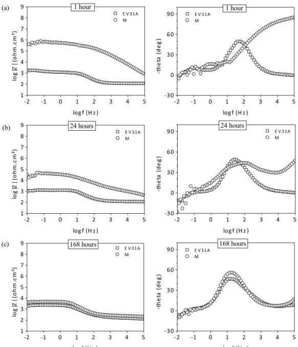
spec-troscopy (EIS) tests were performed (Fig. 4). This technique provides information about the interface of an electrochemical system, which can be the case of a corrosion process[27]. In spe-cific, the impedance modulus at low frequency (Bode impedance modulus diagram) is ascribed to the global resistance of the elec-trochemical system [28]. Moreover, the phenomena shown on the Bode phase diagrams occur at characteristic frequencies that depend of the electrochemical system under study[29].
It may be seen on the Bode modulus diagram that the impedance modulus values of the monolayer hybrid system (M) drops
considerably between 1 h and 24 h of immersion in the corrosive solution, and after 168 h this value is comparable to that of the bare magnesium substrate. This decrease is due to the progressive degradation of the coating induced by the aggressive electrolyte. For the bare magnesium substrate, it was observed a small increase in the impedance modulus values for 168 h of immersion, compared to 24 h of immersion, which can be attributed to the development and stabilization of a partially protective passivity layer at the sur-face of the metallic substrate[30,31].
For every immersion time (1, 24 and 168 h), the Bode phase angle diagram of the bare magnesium substrate shows the pres-ence of two time constants, located at the middle frequency range (∼20 Hz) and at the low frequency range (∼100 mHz). These phenomena can be associated to the capacitive response of the passivity layer of the substrate, and to the charge and species exchanges between the substrate and the electrolyte[32], respec-tively.
On the other hand, the monolayer hybrid system shows the presence of a high frequency time constant (∼100 kHz) at 1 h of immersion (Fig. 4a), which may be attributed to the barrier effect afforded by the epoxy-based coating[21,33]. After 24 h of
Fig. 3. Open circuit potential (Eocp) registered for the bare Mg alloy, and coated by the monolayer hybrid coating (M), during the first hour of immersion in the corrosive solution (0.05 M NaCl).
immersion, the phase angle value for this time constant is consid-erably reduced and continues to decrease progressively with time. This decrease of the barrier properties of the film are related to the liquid intake of the film, which reduces its capacitance value
[12,34], and progressively degrading the protective properties of
the coating. At the same time (24 h), it is possible to observe the apparition of a second time constant in the middle frequency range (∼100 Hz), the same region of that of the bare magnesium sub-strate, and which may be therefore associated to the formation of corrosion products at the metal/coating interface[35,36]. More-over, after 168 h of immersion, both systems the bare substrate and coated by epoxy-based hybrid film, presents one comparable peak around 10 Hz, where in the case of the monolayer hybrid coat-ing it may be attributed to the presence of a porous mixed layer of corrosion products and the sol–gel film. At this stage, the values of the hybrid coating (modulus and phase) are comparable to those of the bare magnesium substrate, meaning that the hybrid coating has lost its protective properties.
Fig. 4. Bode diagrams of the EIS spectra obtained for the bare magnesium substrate, and covered by the monolayer hybrid coating (M), after 1 h (a), 24 h (b) and 168 h (c) of immersion in a 0.05 M NaCl solution.
Table 2
Parameters used for the production of the bilayer sol–gel coatings A–D.
Hybrid coating Layer 1 Layer 2
Withdrawal speed (mm/min) Withdrawal speed (mm/min) Monolayer M 200 – Bilayer A 200 50 B 200 100 C 200 200 D 200 400
The interpretation of the results EIS obtained leads to consider that the monolayer hybrid coating offers an insufficient protection for the metallic substrate when exposed for long periods of time to the corrosive media. These results can be correlated to the SEM observations of the hybrid film that shows an irregular morphology, including macro-such as pits and protuberances, which represents sensible zones to the intrusion of corrosive species through the coating unto the magnesium substrate.
In order to provide a homogeneous and effective protection to the substrate, the architecture of the hybrid coating was modified by the addition of a second layer of the same epoxy composition. 3.3. Bilayer hybrid sol–gel coatings
3.3.1. Variation of the thickness of Layer 2
The “bilayer” architecture consists of a first layer, Layer 1 or “inertion layer”, which would react with the magnesium substrate, partially leveling and “inerting” the surface. The second layer, Layer 2 or “thickening layer” would cover the defects presents on Layer 1 and increase the global thickness of the hybrid coating. In the first place, four bilayer systems were studied, consisting of a first epoxy-based layer (Layer 1) produced with a withdrawal speed of 200 mm/min. The second layer (Layer 2) was produced with with-drawal speeds of 50, 100, 200 and 400 mm/min, in order to obtain four bilayer systems of different global thickness, which are noted
Fig. 6. Average individual layer thickness of the bilayer hybrid systems A–D.
as A–D, respectively. After that, each layer followed a heat treat-ment as described onTable 2.
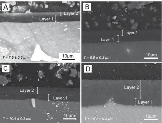
3.3.1.1. Morphological characterization. The SEM observation on mode BSE of the cross-section of the bilayer systems A–D is pre-sented inFig. 5. It is possible to observe that the global thickness of the coating increases with the withdrawal speed applied to the second layer. Besides, some irregularities of the magnesium sub-strate seem covered by the hybrid film, as it may be seen for the bilayer system D, where a protuberance appears under the surface of the hybrid coating.
Furthermore, the individual layers 1 and 2 are visible for most of the bilayer coatings, allowing the measurement of their average thickness. It is to notice that the thickness of the Layer 1 remains constant (5.2 ± 0.3 mm) for all the systems.Fig. 6regroups the global thicknesses of these bilayer coatings and the individual thick-ness for each layer. Besides, it is important to underline that the
Fig. 7. SEM images of the surface of the bilayer hybrid coatings A–D.
thickness of the hybrid coating can be controlled directly on the metallic magnesium substrate, or over a previously sol–gel coated surface of the same nature.
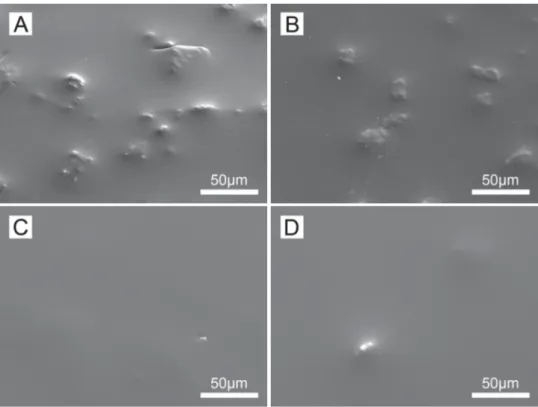
The observation of the surface of the different hybrid bilayer coatings by SEM (Fig. 7) permits to notice the absence of defects and uncovered areas, previously seen on the monolayer hybrid coating. This means that the second layer of hybrid film has recov-ered this kind of defects, even for the lowest thickness of Layer 2 (bilayer system A, 2.3 ± 0.3 mm). Moreover, it may be seen that the irregularities formed by protuberances are less visible as the global thickness of the coating increases, leading to more homogeneous surfaces. This is specially observed in the case of the bilayer systems presenting a thickness equivalent or superior to ∼11 mm (coatings C and D), where the homogeneity of the hybrid film seem consider-ably improved, meaning these defects can be covered with a proper thickness of hybrid film.
3.3.1.2. Electrochemical measurements. The Eocprecords of the bare
magnesium substrate and coated by the bilayer systems A–D during the immersion on the corrosive solution (0.05 M NaCl) are pre-sented inFig. 8. It is to notice that the potential of the systems A and B is follows a similar behavior as the bare magnesium sub-strate, which is also comparable to that of the monolayer hybrid coating previously presented onFig. 3. In contrast, the potential of the bilayer systems C and D is located in a region of nobler poten-tials, a first indication of a superior corrosion resistance for these two bilayer protective systems.
The EIS analyze of the systems A–D after 1 h of immersion in a 0.05 M NaCl solution (Fig. 9a) shows high impedance modu-lus values for all the systems, compared to the magnesium bare substrate. As well as, a high frequency time constant (ascribed to the barrier effect of the sol–gel film), can be observed repre-senting the effectiveness of the protective coating during for short periods of contact with the corrosive solution. The impedance modulus values increase with the global thickness of the hybrid film.
However, the absorption of liquid into the hybrid film and the attack of corrosive species leads to the reduction of the impedance modulus values of the system, as it may be seen after 24 h of immer-sion (Fig. 9b), and finally after a much longer time period of 168 h
(Fig. 9c), where both the low frequency impedance modulus and
the high frequency time constant obtained for the protective sys-tems A and B are comparable with that of the bare magnesium substrate. Moreover, the apparition of an intermediate layer of cor-rosion products at the substrate/coating interface is characterized by a well-defined second time constant in the middle frequency range (about 1–100 Hz). Nevertheless, here again the systems C and D shows a high value of both impedance modulus values and phase angle, even after 168 h of immersion in the corrosive media. This effect is more remarkable in the case of the bilayer system D, indicating that the electrochemical characteristics rises with the augmentation of the hybrid film thickness. Besides, for the bilayer system D it is not possible to observe the presence of the phenomenon in the middle frequency, observed for all the other systems and associated to the film degradation and corrosion
Fig. 8. Open circuit potential (Eocp) registered for the bilayer systems: A–D, during the first hour of immersion in the corrosive solution (0.05 M NaCl).
Fig. 9. Bode diagrams of the EIS spectra obtained for the bare magnesium substrate, and covered by the bilayer systems A–D, after 1 h (a), 24 h (b) and 168 h (c) of immersion in 0.05 M of NaCl.
products at the substrate/coating interface, which indicate the superior barrier effect of this hybrid film system compared to the others.
Although the systems A–D have all a second hybrid layer (Layer 2) that successfully covers the defects observed in the Layer 1, the electrochemical measurements shows that the bilayer systems A and B have a similar behavior to that of the monolayer hybrid coating (M), losing its protective characteristics when in contact with the corrosive electrolyte for extended time periods. However, the thickness increase of the Layer 2 to ∼5 mm or higher, permits to obtain higher electrochemical values for the system, and so to increase the durability of the protective hybrid coating. Here, it may be considered that a global thickness of ∼11 mm is a threshold value permitting to achieve an effective anticorrosion protection for this epoxy-based bilayer coating.
The last bilayer systems presented have all an equivalent “iner-tion layer” thickness of around 5 mm, and as a consequence, the influence of coating with a Layer 1 of different thickness, lower of higher than 5 mm is an interesting aspect to evaluate the corrosion
resistance of these bilayer architectures. The next section of this work proposes the creation of two different thicknesses of Layer 1 for a similar thickness of Layer 2, in order to obtain two different bilayer systems.
3.3.2. Variation of the thickness of Layer 1
For the study of the thickness “inertion layer” (Layer 1) influence, two other bilayer systems were prepared, with the parameters listed onTable 3. These bilayer coatings are called D′and A′, since
Table 3
Parameters used for the production of the bilayer sol–gel coatings D′and A′. Hybrid coating Layer 1 Layer 2
Withdrawal speed (mm/min) Withdrawal speed (mm/min) Bilayer D′ 400 200 A′ 50 200
Fig. 10. SEM images on mode BSE of the cross-section of the bilayer coatings D′and A′.
it is expected to possess an equivalent global thickness to that of the systems D and A.
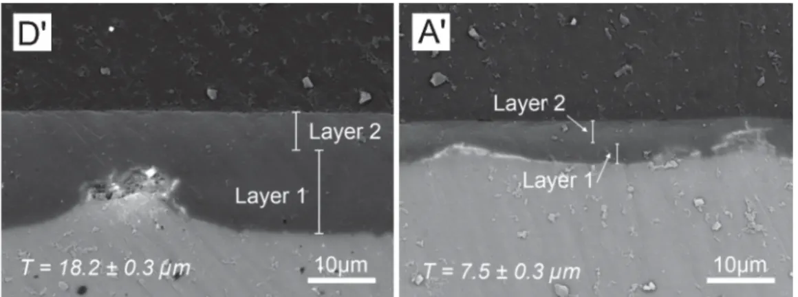
3.3.2.1. Morphological characterization. Fig. 10 shows the SEM observation (BSE mode) of the cross-section of the bilayer systems D′and A′, permitting to measure the global and individual thickness
of the bilayer coatings. These values are plotted onFig. 11. It may be seen that the global thickness of the systems D and D′are
identi-cal (around 18 mm), and the thickness obtained for each individual layer corresponds to the withdrawal speed applied during the dip-coating, even if the withdrawal speeds of Layer 1 and Layer 2 of the systems D and D′are inverse. In other words, the global thickness
for either systems D and D′is equivalent, even if the thicknesses of
the “inertion layer” and the “thickening layer” are different. 3.3.2.2. Electrochemical characterization. The results of the Eocp
measurements for the bilayer system D′ during the first hour of
immersion on the corrosive solution are presented inFig. 13, and compared with those obtained for the bilayer system D. With an identical global thickness, these bilayer systems (D and D′) show
a similar behavior of potential during the immersion, located in a nobler region than that of the bare magnesium alloy, and to the bilayer systems A and B previously presented. The high values of potential presented by the system D′denotes an efficient barrier
effect that temporary prevents the passage of the electrolyte unto the metallic substrate.
Fig. 11. Average individual layer thickness of the bilayer hybrid systems D and D′, A and A′.
After the OCP measurements, the bilayer system D′ samples
were analyzed by EIS in the corrosive solution, showing that this protective coating possess a high impedance modulus and phase angle values, in the first hours of immersion (Fig. 14a). This behav-ior can be associated to the high barrier effect of these hybrid films (bilayer system D and D′, which present the same global
thickness layer, around 18um). Nonetheless, both the resistance and the phase angle of the bilayer system D′, which presents the
higher Layer 1 thickness (13um), decreases dramatically after 24 h in contact with the aggressive solution (Fig. 14b). Furthermore, the impedance modulus values of this system are similar to those of the bare magnesium substrate after 168 h of immersion, representing the major degradation of the protective properties of this coating. It is important to underline the difference on behavior between these systems of identical global thickness: D and D′. The bilayer system
D shows a high impedance modulus and phase angle values at the end of the EIS test (168 h of immersion), that may be ascribed to an efficient barrier effect. On the other hand, the bilayer system D′ presents not only a rapid diminution of the impedance
mod-ulus and phase angle values), from 24 h of immersion, presented a well-defined second time constant at middle frequency, which evidences the formation of corrosion products, result of the inter-action between the electrolyte and the magnesium substrate, as it was mentioned before.
This example shows that coating with a thicker “inertion layer” under these conditions does not necessarily leads to an increase of the corrosion resistance. The sol–gel coatings (>1 mm) are suscep-tible to cracking[37], and also diminishes the evaporation rate of solvents during drying[38]. In that case, the creation of a Layer 1
Fig. 12. Average individual layer thickness of the bilayer hybrid systems A′, C and D′.
Fig. 13. Open circuit potential (Eocp) registered for the bilayer systems: D and D′, during the first hour of immersion in the corrosive solution (0.05 M NaCl).
with 13 ± 0.3 mm of thickness may represent an excessive amount of solvents that could not be completely evaporated applying the current heat treatment. Imprisoned inside the hybrid film, the solvents and water would disable the full reticulation and con-solidation of the solid network of the sol–gel film and therefore permitting the passage of liquid and corrosive species unto the metallic substrate.
It is important to underline the fact that the “inertion layer” (Layer 1) of all the bilayer systems here presented undergoes a heat treatment twice: the first one is applied after coating with Layer 1 and the second is indirectly applied at the same time for Layer 2. This means that the solid network of Layer 1 would be better consol-idated than that of Layer 2. Even though the “inertion layer” of the systems D and D′followed an identical heat treatment, their
thick-ness would seem to be a crucial factor on the corrosion protection of the magnesium substrate.
As for the “thickening layer” (Layer 2), the solvents and water are able to escape even after the drying stage of the coating, since this layer remain in direct contact with the environment. Hence, even if
Fig. 14. Bode diagrams of the EIS spectra obtained for the bare magnesium substrate, and covered by the bilayer systems D and D′, after 1 h (a), 24 h (b) and 168 h (c) of immersion in 0.05 M of NaCl.
the “thickening layer” presents an important thickness (∼13 mm), as it is the case of the bilayer system D, it can evaporate the solvents easily because there is no solid barrier between this layer and the environment. On the other hand, in the case where the thickest layer is the “inertion layer” (Layer 1), as for the bilayer system D′
(∼13 mm), the “thickening layer” (Layer 2) would act as a physi-cal barrier that partially obstructs the evaporation of solvents and water during drying of the coating.
Despite these two bilayer coatings possess the same global thickness, they show a remarkable difference in anticorrosion per-formances, as it has been proved by the electrochemical tests. Here, the bilayer system D presents the best electrochemical val-ues, and so the best corrosion performances. With an equivalent global thickness to system D′, the “inertion layer” of this bilayer
coating is of about 5 mm thick, which would contain an inferior quantity of solvents easier to evaporate, permitting to achieve a better reticulation than an “inertion layer” of ∼13 mm.
In this context, the preparation of a bilayer coating with an “iner-tion layer” inferior to ∼5 mm, which is the case of the bilayer system
Fig. 15. Open circuit potential (Eocp) registered for the bilayer systems: A and A′, during the first hour of immersion in the corrosive solution (0.05 M NaCl).
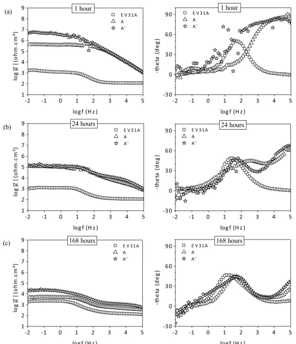
Fig. 16. Bode diagrams of the EIS spectra obtained for the bare magnesium substrate, and covered by the bilayer systems A and A′, after 1 h (a), 24 h (b) and 168 h (c) of immersion in 0.05 M of NaCl.
A′, would help to support the previous observations. First, the Eocp
record of this coating (Fig. 15) during the first hour of immersion in the corrosive solution shows no remarkable difference with the behavior shown by the bilayer system A, which possess an equiv-alent global thickness. Besides, both of the hybrid films present an Eocppotential equivalent to that of the bare magnesium substrate
and to the monolayer hybrid coating (Fig. 3).
The EIS spectra of the bilayer system A′at 1 h, 24 h and 168 h
(Fig. 16), shows a similar behavior to that of the bilayer system A. And the impedance modulus values of these systems decreases at similar rates with the immersion time. Besides, the high frequency time constant observed in these coatings diminishes simultane-ously with the immersion time, probably due to the formation of corrosion products after 24 h (depicted by a middle frequency time constant). For these two bilayer coatings of equivalent global thick-ness, A and A′, the change on thickness for the “inertion layer” do not
modifies considerably the electrochemical properties of the system. From another point of view, both systems D′ and A′ possess
an identical Layer 2 (∼5 mm), as well as the previously presented system C. Here, these three bilayer systems present an equivalent thickness of Layer 2, with an increasing thickness of Layer 1 in the order: A′, C and D′.Fig. 12regroups the individual layer thickness for
these systems. It is important to underline that the electrochemical characteristics of system A′have been shown to behave in the same
way of the monolayer hybrid coating, insufficient to ensure the pro-tection of the metallic substrate. In contrast, when the thickness of Layer 1 is equivalent to ∼5 mm (system C), the protective perfor-mances of the coating considerably increase. However, the creation of an “inertion layer” with a significant thickness (∼13 mm) like in the case of the system D′, the protective properties of the coating are
severely diminished. The thickness of Layer 1 seem to have a strong influence on the final properties of the bilayer coating, rising the durability of the system when it’s thickness is equivalent to 5 mm, as it is observed in the case of system C. In the case of an impor-tant thickness (13 mm), this may represent an excessive amount of solvents to evaporate so the full reticulation of the coating is not achieved, as it was observed in the case of the system D′.
The electrochemical results here presented suggest a strong relationship between the architecture of the bilayer systems and their anticorrosion performances. The first part of the study of bilayer systems: A–D, with a Layer 1 thickness of 5.2 ± 0.3 mm, have shown that it is necessary to increase the thickness of the Layer 2 equal or greater than ∼5 mm in order to achieve satisfactory anticorrosion performances. Lower thicknesses for this second hybrid layer will lead to performances comparable to those of a monolayer film.
Finally, the second part of the study of bilayer systems, it was observed that increasing the thickness of the “inertion layer” will not necessarily improve the anticorrosion performances of the sys-tem, as it was noted for the bilayer coating D′, which presents a
Layer 1 thickness equivalent to ∼13 mm. On the other hand, coating with an “inertion layer” of inferior thickness (∼2 mm) has no signifi-cant influence on the anticorrosion performances, when compared to a bilayer system with an equivalent global thickness as it was shown for the systems A and A′.
An important influence of the thicknesses of both the “iner-tion layer” and the “thickening layer” is observed, which may be attributed to parameters like the solvent accumulation and evap-oration inside Layer 1, the reticulation and condensation degree of the sol–gel network, the heat treatment performed or even the reactivity of the magnesium substrate.
4. Conclusions
The present work reports the use of different architectural arrangements for a bilayer epoxy-based sol–gel coating for the
corrosion protection of a magnesium alloy. The morphological analyze of the monolayer architecture evidences the presence of macro-defects which would potentially decrease the anticorrosion protection of this coating, as it is shown by the EIS analyze in a chloride solution. Therefore, a second or “thickening” layer of the epoxy-based coating was added in order to cover the defects of the first or “inertion” layer, and also to increase the global thickness of the coating.
First, it is shown that for an “inertion layer” of a thickness of 5 mm, the “thickening” layer shall present the same thickness (5 mm) in order to increase the anticorrosion performances of the system. Otherwise the bilayer system shows the same perfor-mances resembles to those of the monolayer architecture of the epoxy-based coating. The best anticorrosion performances were obtained for the bilayer system presenting the highest global thick-ness (18 mm), the system D.
Second, the thickness of the second layer was set to a con-stant value of ∼5 mm as for the “inertion” layer it was increased to ∼13 mm, resulting on lower anticorrosion performances com-pared to a coating with equivalent global thickness but inversed architecture. Here, the accumulation of solvents inside the “iner-tion” layer would lead to a lower reticulation degree, and so to the diminution of the protective properties of the bilayer system.
The study of the epoxy-based sol–gel film here presented shows that a single layer of this coating is not enough to ensure the pro-tection of the magnesium alloy, and that it may be covered with a second layer of the same chemical nature. However, the architec-ture of this coating has an important role on the final anticorrosion performances of the system, just as much as the thickness of the protective system.
Acknowledgments
The present work was carried out as a part of the CARAIBE project. The FDA and the OSEO are gratefully acknowledged for the financial support for this project. The authors are grateful to the collaborators of this project: Liebherr, Turbomeca, Eurocopter, Mecaprotec, and the Institut Carnot CIRIMAT. A special acknowl-edgment is recognized to the LAPEC of the UFRGS, for the research contribution to this work.
References
[1]G. Ballerini, U. Bardi, R. Bignucolo, G. Ceraolo, About some corrosion mecha-nisms of AZ91D magnesium alloy, Corros. Sci. 47 (2005) 2173–2184.
[2]R. Winston Revie, H.H. Uhlig, Corrosion and Corrosion Control—An Introduc-tion to Corrosion Science and Engineering, Wiley Interscience, Hoboken, New Jersey, USA, 2008.
[3]X. Zhang, K. Zhang, X. Deng, H. Li, Y. Li, M. Ma, et al., Corrosion behavior of Mg Y alloy in NaCl aqueous solution, Prog. Nat. Sci.: Mater. Int. 22 (2012) 169–174.
[4]Q. Wang, Y. Liu, S. Fang, Y. Song, D. Zhang, L. Zhang, et al., Evaluating the improvement of corrosion residual strength by adding 1.0 wt.% yttrium into an AZ91D magnesium alloy, Mater. Charact. 61 (2010) 674–682.
[5]S. Zheng, J. Li, Inorganic organic sol gel hybrid coatings for corrosion protection of metals, J. Sol-Gel Sci. Technol. 54 (2010) 174–187.
[6]J. Wen, G.L. Wilkes, Organic/inorganic hybrid network materials by the sol–gel approach, Chem. Mater. 8 (1996) 1667–1681.
[7]S.R. Davis, A.R. Brough, A. Atkinson, Formation of silica epoxy hybrid network polymers, J. Non-Cryst. Solids 315 (2003) 197–205.
[8]J.B. Cambon, F. Ansart, J-P. Bonino, V. Turq, Effect of cerium concentration on corrosion resistance and polymerization of hybrid sol gel coating on martensitic stainless steel, Prog. Org. Coat. 75 (2012) 486–493.
[9]C.F. Malfatti, T.L. Menezes, C. Radtke, J. Esteban, F. Ansart, J-P. Bonino, The influence of cerium ion concentrations on the characteristics of hybrid films obtained on AA2024-T3 aluminium alloy, Mater. Corros. 63 (2012) 819–827.
[10]V. Meiffren, K. Dumont, P. Lenormand, F. Ansart, S. Manov, Development of new processes to protect zinc against corrosion, suitable for on-site use, Prog. Org. Coat. 71 (2011) 329–335.
[11]A. Zomorodian, F. Brusciotti, A. Fernandes, M.J. Carmezim, T. Moura e Silva, J.C.S. Fernandes, et al., Anti-corrosion performance of a new silane coating for corrosion protection of AZ31 magnesium alloy in hank’s solution, Surf. Coat. Technol. 206 (2012) 4368–4375.
[12]F. Brusciotti, D.V. Snihirova, H. Xue, M.F. Montemor, S.V. Lamaka, M.G.S. Fer-reira, Hybrid epoxy silane coatings for improved corrosion protection of Mg alloy, Corros. Sci. 67 (2013) 82–90.
[13]S.V. Lamaka, M.F. Montemor, A.F. Galio, M.L. Zheludkevich, C. Trinidade, L.F. Dick, et al., Novel hybrid sol–gel coatings for corrosion protection of AZ31B, Electrochim. Acta 53 (2008) 4773–4783.
[14]X. Zhong, Q. Li, J. Hu, S. Zhang, B. Chen, S. Xu, et al., A novel approach to heal the sol–gel coating system on magnesium alloy for corrosion protection, Elec-trochim. Acta 55 (2010) 2424–2429.
[15]X. Guo, M. An, Experimental study of electrochemical corrosion behaviour of bilayer on AZ31B Mg alloy, Corros. Sci. 52 (2010) 4017–4027.
[16]X. Zhong, Q. Li, J. Hu, X. Yang, F. Luo, Y. Dai, Effect of cerium concentration on microstructure, morphology and corrosion resistance of cerium silica hybrid coatings on magnesium alloy AZ91D, Prog. Org. Coat. 69 (2010) 52–56.
[17]R. Gadow, E.J. Gammel, F. Lenhert, D. Scherer, J.I. Skar, Coating system for mag-nesium die castings in Class A surface quality, in: Magmag-nesium Alloys and Their Application, 2000, pp. 492.
[18]Y.H. Du, M. Damron, G. Tang, H. Zheng, C.J. Chu, J.H. Osborne, Inorganic/organic hybrid coatings for aircraft aluminum alloy substrates, Prog. Org. Coat. 41 (2001) 226–232.
[19]F. Zucchi, V. Grassi, A. Frignani, C. Monticelli, G. Trabanelli, Influence of a silane treatment on the corrosion resistance of a WE43 Mg alloy, Surf. Coat. Technol. 200 (2006) 4136–4143.
[20]Z. Yong, J. Zhu, C. Qiu, Y. Liu, Molybdate phosphate composite conversion coat-ing on magnesium alloy surface for corrosion protection, Appl. Surf. Sci. 255 (2008) 1672–1680.
[21]S.V. Lamaka, G. Knörnschild, D.V. Snihirova, M.G. Taryba, M.L. Zheludkevich, M.G.S. Ferreira, Complex anticorrosion coating for ZK30 magnesium alloy, Elec-trochim. Acta 55 (2009) 131–141.
[22]Z. Li, X. Jing, Y. Yuan, M. Zhang, Composite coatings on a Mg Li alloy prepared by combined plasma electrolytic oxidation and sol–gel techniques, Corros. Sci. 63 (2012) 358–366.
[23]A.L.K. Tan, A.M. Soutar, I.F. Annergren, Y.N. Liu, Multilayer sol–gel coat-ings for corrosion protection of magnesium, Surf. Coat. Technol. 198 (2005) 478–482.
[24]H. Shi, F. Liu, E. Han, Corrosion protection of AZ91D magnesium alloy with sol–gel coating containing 2 methyl piperidine, Prog. Org. Coat. 66 (2009) 183–191.
[25]J. Hu, Q. Li, X. Zhong, L. Zhang, B. Chen, Composite anticorrosion coatings for AZ91D magnesium alloy with molybdate conversion coating and silicon solgel coatings, Prog. Org. Coat. 66 (2009) 199–205.
[26]U.C. Nwaogu, C. Blawert, N. Scharnagl, W. Dietzel, K.U. Kainer, Influence of inor-ganic acid pickling on the corrosion resistance of Mg alloy AZ31 sheet, Corros. Sci. 51 (2009) 2544–2556.
[27]C. Gabrielli, Identification of Electrochemical Processes by Frequency Response Analysis, Solartron Analytical, Paris, France, 1998.
[28]G.W. Walter, A review of impedance plot methods used for corrosion perfor-mance analysis of painted metals, Corros. Sci. 26 (1986) 681–703.
[29]C. Gabrielli, H. Takenouti, Méthodes électrochimiques appliquées à la corrosion—techniques dynamiques, Techniques de L’ingénieur, Paris, France, 2010, cor811.
[30]F. Zucchi, V. Grassi, C. Monticelli, G. Trabanelli, Electrochemical behaviour of a magnesium alloy containing rare earth elements, J. Appl. Electrochem. 36 (2006) 195–204.
[31]X. Guo, J. Chang, S. He, W. Ding, X. Wang, Investigation of corrosion behaviors of Mg 6Gd 3Y 0.4Zr alloy in NaCl aqueous solutions, Electrochim. Acta 52 (2007) 2570–2579.
[32]P.S. Correa, C.F. Malfatti, D.S. Azambuja, Corrosion behaviour study of AZ91 magnesium alloy coated with methyltriethoxysilane doped with cerium ions, Prog. Org. Coat. 72 (2011) 739–747.
[33]P.C. Banerjee, R.K.S. Raman, Electrochemical impedance spectroscopic inves-tigation of the role of alkaline pretreatment in corrosion resistance of a silane coating on magnesium alloy ZE41, Electrochim. Acta 56 (2011) 3790– 3798.
[34]A. Conde, A. Duran, J.J. de Damborenea, Polymeric sol–gel coatings as protective layers of aluminium alloys, Prog. Org. Coat. 46 (2003) 288–296.
[35]A.F. Galio, S.V. Lamaka, M.L. Zheludkevich, L.F. Dick, I.L. Müller, M.G.S. Ferreira, Inhibitor doped sol–gel coatings for corrosion protection of MG AZ31, Surf. Coat. Technol. 204 (2010) 1479–1486.
[36]F. Zanotto, V. Grassi, A. Frignani, F. Zucchi, Protection of the AZ31 magnesium alloy with cerium modified silane coatings, Mater. Chem. Phys. 129 (2011) 1–8.
[37]C.J. Brinker, G.W. Scherer, Sol–Gel Science: The Physics and Chemistry of Sol–Gel Processing, Academic Press Inc., San Diego, USA, 1990.
[38]E. Certhoux, F. Ansart, V. Turq, J-P. Bonino, J.M. Sobrino, J. Garcia, et al., New sol–gel formulations to increase the barrier effect of a protective coating against the corrosion of steels, Prog. Org. Coat. 76 (2013) 165–172.