HAL Id: hal-00614168
https://hal.archives-ouvertes.fr/hal-00614168
Submitted on 11 Aug 2011
HAL is a multi-disciplinary open access
archive for the deposit and dissemination of
sci-entific research documents, whether they are
pub-lished or not. The documents may come from
teaching and research institutions in France or
abroad, or from public or private research centers.
L’archive ouverte pluridisciplinaire HAL, est
destinée au dépôt et à la diffusion de documents
scientifiques de niveau recherche, publiés ou non,
émanant des établissements d’enseignement et de
recherche français ou étrangers, des laboratoires
publics ou privés.
A sighted aerial robot with fast gaze and heading
stabilization
Lubin Kerhuel, Stéphane Viollet, Nicolas Franceschini
To cite this version:
Lubin Kerhuel, Stéphane Viollet, Nicolas Franceschini. A sighted aerial robot with fast gaze and
heading stabilization. IEEE/RSJ International Conference on Intelligent Robots and Systems, Oct
2007, San Diego, United States. pp.WeD5.4. �hal-00614168�
A sighted aerial robot with fast gaze and heading stabilization
(Authors version) -
doi:10.1109/IROS.2007.4399497
Proceedings of the 2007 IEEE/RSJ International Conference on Intelligent Robots and Systems
San Diego, CA, USA, Oct 29 - Nov 2, 2007
L. Kerhuel, S. Viollet, Member, IEEE, and N. Franceschini
Abstract— Autonomous guidance of Micro-Air Vehicles
(MAVs) in unknown environments is a challenging task because these artificial creatures have small aeromechanical time con-stants, which make them prone to be disturbed by gusts of wind. Flying insects are subject to quite similar kinds of disturbances, yet they navigate swiftly and deftly. Flying insects display high-performance visuo-motor control systems that have stood the test of time. They can therefore teach us how vision can be used for immediate and vital actions.
We built a 50-gram tethered aerial demonstrator, called OSCAR II, which manages to keep its gaze steadily fixating a target (a dark edge), in spite of nasty thumps that we deliberately gave to its body with a custom-made “slapping machine”. The robot’s agile yaw reactions are based on:
• a mechanical decoupling of the eye from the body
• an active coupling of the robot’s heading with its gaze
• a Visual Fixation Reflex (VFR)
• a Vestibulo-Ocular Reflex (VOR)
• an accurate and fast actuator (Voice Coil Motor, VCM)
The actuator is a 2.4-gram voice coil motor that is able to rotate the eye with a rise time as small as 12ms, that is, much shorter than the rise time of human oculo-motor saccades. In connection with a micro-rate gyro, this actuator endows the robot with a high performance “vestibulo ocular reflex” that keeps the gaze locked onto the target whatever perturbations in yaw affect the robot’s body. Whenever the robot is destabilized (e.g., by a slap applied on one side), the gaze keeps fixating the target, while being the reference to which the robot’s heading is servoed. It then takes the robot only 0.6s to realign its heading with its gaze.
ACRONYMS VFR Visual Fixation Reflex VOR Vestibulo-Ocular Reflex VCM Voice Coil Motor FOV Field Of View
EMD Elementary Motion Detector ZSL Zero-Setting Limiter GCS Gaze Control System HCS Heading Control System
I. INTRODUCTION
Ever since the first visual systems appeared in the Cam-brian era, selection pressure led many living creatures to stabilize their line of sight (i.e., their gaze). Navigating in 3D environments, hovering [1], tracking mates [2] and intercepting prey [3] are among the behavioural feats that L. Kerhuel, S. Viollet and N. Franceschini are with the Biorobotics Dept. at the Movement and Perception Institute, CNRS/Univ de la Méditerranée, CP 938, 163, avenue de Luminy, 13288 Marseille Cedex 09, France (email: [email protected], {stephane.viollet,nicolas.franceschini}@univmed.fr)
flying insects achieve under visual guidance. Recent studies in free-flying flies have shown that these animals maintain their gaze fixed in space for about 100ms episodes, using very fast reflexes [4]. In the vertebrates too, eye movements are the fastest and the most accurate movements generated. Gaze stabilization is a difficult task to achieve by all animals because the eye actuator must be both :
• fast, to compensate for sudden, untoward disturbances. • accurate, to ensure stable visual fixation.
In the flying fly, an active mechanism for gaze stabilization prevents the insect from being flummoxed adversely affected by disturbances affecting its flight such as vibrations or body jerks that may result from turbulences [4], [5]. Such a mechanism is far beyond what present-day robotics can achieve.
Several studies have considered implementing an active gaze stabilization system into mobile robots. A gaze control system combining a retinal position measurement with an inertial measurement has been proposed [6], and its perfor-mances were assessed qualitatively using slow perturbations applied by hand. Shibata and Schaal [7] described a gaze control system based on an inverse model of the mammalian oculomotor plant. Enhanced by a learning network, this system was able to decrease the retinal slip 4-fold for sinusoidal perturbations applied at moderate frequencies (up to 0.8Hz). Likewise, an adaptive image stabilizer for a robotic agent was built and tested by applying perturbations at moderate frequencies (up to 0.6Hz) [8]. Two other gaze stabilization systems inspired by the human Vestibulo-Ocular Reflex (VOR) have been presented [9], [10], but their perfor-mances have not been assessed quantitatively on a test-bed yet. Twombly [11] has made simulation experiments on a neuro-vestibular control system aimed at endowing a walk-ing robot with active image stabilization. In the humanoid research field, a few robotic realizations have highlighted the need for stabilizing the gaze by using visuo/inertial oculomotor reflexes (e.g.: [8]). Wagner et al. built a fast responding oculomotor system [12] using air bearings and bulky galvanometers. None of the technological solutions ever proposed are compatible, however, with the stringent constraints imposed upon Micro-Air Vehicles (MAVs).
Gaze stabilization mechanisms in flying insects, particu-larly in flies, are a paragon of oculomotor reflexes that are key to heading stabilization. These high performance reflexes are of particular interest to the design of tomorrow’s terres-trial, aerial, underwater and space autonomous vehicles with
fast dynamics. Visually mediated stabilization of heading requires:
• a mechanical decoupling of the eye from the body (via a neck, as in flies, or via the orbit, as in the vertebrate visual system).
• an accurate and fast actuator for orienting the gaze. A fly has no less than 23 pairs of micro-muscles to control its gaze [13].
• a Visual Fixation Reflex (VFR) that keeps the gaze steadily on the target.
• a Vestibulo-Ocular Reflex (VOR), i.e., an active inertial reflex that rotates the eye in counter phase with the head. Flies typically exhibit such an inertial reflex, in particular for roll, based on the halteres gyroscopic organ [5]. A similar system was developed a hundred million years later in mammals, including humans. Rhesus monkeys’VORreact in the 0.5 − 5Hz [14] and even 5 − 25Hz [15] frequency ranges, thus exhibiting higher VORperformances than humans.
• an active coupling of the robot’s heading with the gaze, via oculo-motor reflexes.
• a proprioceptive sensor able to measure the angular position of the eye in the head or in the body. Though still controversial in the case of the primate oculomotor system [16] this sensor exists in flies in terms of a pair of mechanosensory hair fields in the neck region [17], [18] that allow head-body angular deviations in pitch [4], roll [5] and yaw [19] to be measured and compensated for. In section 2, we describe our current aerial robot, called OSCAR II. OSCAR II differs from the original (OSCAR I [20], [21]) robot in that the eye is now mechanically uncoupled from the body, a configuration that will permit the gaze to be actively locked onto the target, whatever disturbances may affect the robot’s body. In Section 3, we describe the scheme underlying the fast and accurate control of the “eye-in-robot” angle. In section 4, we explain how we merged a Gaze Control System (GCS) with a Heading Control System (HCS). In section 5, the robot’s yaw control strategy is detailed, and we demonstrate the unusual per-formances attained for the overall gaze and heading control systems, which are both able to counteract nasty thumps given to the robot’s body.
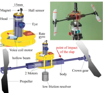
II. DESCRIPTION OF THEOSCAR IIROBOT OSCAR II is a miniature (50-gram) twin-engine aerial platform equipped with a one-axis (horizontal) oculomotor mechanism (Fig.1).
The seeing robot is able to adjust its heading accurately about the yaw axis by driving its two propellers differentially, via a custom-made dual sensorless speed governor (not described here). The robot’s “body” consists of a carbon housing enclosing the two motors. It is prolonged on each side by a hollow beam within which the propeller carbon drive shaft can turn frictionlessly on micro ball bearings (Fig. 1). The robot’s “head” is a large (diameter 15mm) carbon tube mounted firmly onto the motor housing. Within the head, an inner carbon “eye tube” mounted on pivot bearings
Fig. 1. OSCAR II is a 50-gram aerial robot that is able to control its heading about the vertical (yaw) axis by driving its two propellers differentially on the basis of what it sees. The eye of OSCAR II is mechanically uncoupled from the head, which is itself fixed to the “body”. A Gaze Control System (GCS) (Fig.5) allows the robot to fixate a target (a vertical white-dark edge placed 60 centimeters ahead), thus stabilizing its gaze despite severe disturbances (gusts of wind, slaps) that may affect its body. A Heading Control System (HCS) (Fig.5), merged with theGCS, allows the robot’s heading to catch up with the gaze, and thus to stabilize the heading in the same direction as the gaze. The right inset shows the current version of the OSCAR II robot mounted onto a low-friction, low-inertia resolver that allows its heading to be monitored accurately.
can turn freely about the yaw axis. The eye tube is spring-loaded between a pivot bearing (at the bottom part) and a micro-conical ball bearing (top part) through which a steel axle passes freely. A micromagnet glued to the tip of this axle allows the eye azimuthal orientation Θer in the robot to be measured by a Hall sensor.
The robot’s eye consists of a miniature lens (diameter 5mm, focal length 8.5mm) with an elementary “retina”. The retina, composed of a single pair of matched PIN photodi-odes, scans at 10Hz by means of a fast piezo bender (Physik Instrumente) driven by an onboard waveform generator cir-cuit (for details, see [22]). This retinal microscanning process is inspired by the one we identified in the fly compound eye [23]. The microscanning motion of the two photoreceptors occurs perpendicularly to the lens’ axis, making their line-of-sights deviate in concert periodically. For details on the whys and wherefores of the particular microscanning law adopted, the reader is referred to our original analyses and simulations of the OSCAR sensor principle [24]. In essence, we showed that the association of an exponential scan with an Elementary Motion Detector (EMD) gives rise to a genuine Angular Position Sensor that is able to sense the position of an edge or a bar at high accuracy within its relatively small Field Of View (FOV) (FOV = ±1.4 deg, i.e., about equal to theFOVof the human fovea). We showed that this sensor boasts a 40-fold better angular resolution than the inter-receptor angle, in the task of locating an edge, and can
therefore be said to be endowed with hyperacuity [25]. For further details on the performances (accuracy, calibration) of this microscanning visual sensor, the reader is referred to [22].
III. IMPLEMENTATION OF THE ROBOT’S OCULOMOTOR SYSTEM
In the human oculomotor system, extra-ocular muscles (EOM) show performances that are often deemed contra-dictory. On the one hand, they are required to maintain the gaze fixated accurately onto a steady target [26]. On the other hand, they are required to rotate the eye with a very small response time: a saccade of moderate amplitude takes only about 100ms [27]. We emulated the high performance human oculomotor system by controlling the orientation of the eye-tube with an unconventional extra-ocular actuator: a Voice Coil Motor (VCM) that was dissected out from a hard disk microdrive (Hitachi). A VCM (normally used to displace the read/write head in disk drive control systems [28]) makes no trade-off between high positional accuracy and fast displacement.
Fig. 2 shows a top view scheme of the novel miniature oculomotor system that we built and installed on OSCAR II’s body.
Fig. 2. OSCAR II oculomotor mechanism (top view). The central “eye tube” equipped with its two-pixel piezo-scanning retina (not shown here) is inserted into a larger carbon tube (“the head”) that is mounted firmly onto the robot’s body. The eye tube is mechanically uncoupled from the head with one degree of freedom about the yaw axis. The angle θerbetween the
robot’s heading and the gaze is finely controlled (via the linkage rod and the control horn) by a microVCMextracted from a hard disk microdrive. The visual sensor’s output is a linear and even function of θt− θgaze.
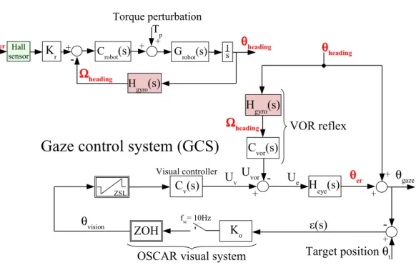
VCMcontrol requires an accurate position feedback loop. We used a simple PID structure to servo the angular position “eye in robot” θer to the reference input Ue (Fig.3). θer was measured by placing a Hall sensor in front of a micro magnet (1mm3) glued to the eye-tube’s rotation axle (see Fig.1, left
inset). All the transfer functions of Fig. 3 and 5 are detailed in the appendix. Uvcm + -Ue Geye(s) CPI(s) CPD(s) θer CLP(s) F(s) Heye(s) Hall sensor
Fig. 3. Block diagram (noted Heye(s)) of the Voice Coil Motor (VCM) servo
system that makes the “eye in robot” angle θerfollow the reference input Ue.
The Geyetransfer function models the dynamic of theVCMloaded by the
eye. CPI and CPDare the proportional-integral and proportional-derivative
terms of the feedback controller, respectively. The CLP transfer function
corresponds to a low pass filter that removes high frequency noise brought about by the Hall sensor. F(s) is a 2ndorder low-pass filter that limits the
step response overshoot. F(s), CPI, CLPand CPDare digitized (sample rate
1ms) and implemented in the same dsPIC microcontroller.
The output of the Hall sensor is noisy. Though the high frequency noise (above 200Hz) has little impact on theVCM
position, it markedly increases the electrical consumption of the VCM. We therefore used a low pass filter (CLP), with a cut-off frequency of 200Hz. This filter does not affect the overall performances of the position feedback loop.
Fig. 4. Response of the “eye in robot” angular position θer to a large
(10-degree) step input applied to the reference input Ue(Fig.3). To improve
the readability, the red curve is the filtered version of the raw θerdata (cyan
curve) using a 4thzero phase delay filter (cut-off frequency at 40Hz). The
use of a voice coil motor actuator allows the closed loop rise time to reach an unusually small value (Trise= 12ms).
The step response shown in Fig. 4 illustrates the very fast dynamics attained in controlling the orientation of the eye in the robot: θer has a settling time Tsettle (at 94%) as small as 44ms and a rise time Trise as small as 12ms. The mean velocity attained during the rising phase is 660 deg /s, which is higher than the velocity (180 deg /s) reached in our
H
gyro(s)
C
vor(s)
H
eye(s)
K
oZOH
fsc= 10Hzθ
headingθ
gazeθ
erTarget position
θ
t +-
+ + -+U
eU
vU
vorOSCAR visual system
Visual controller
Ω
headingε(s)
C
v(s)
VOR reflex
ZSL + + + -H gyro(s)
G robot(s) Crobot(s)
θ
headingθ
er Torque perturbation ΤpK
r Hall sensorΩ
headingGaze control system (GCS)
Heading control system (HCS)
1 s
θ
visionFig. 5. Block diagrams of the two intertwined control systems (anHCSand aGCS) which are implemented onboard the OSCAR II robot. TheGCSkeeps the gaze (θgaze) locked onto a stationary target (bearing θt), despite heading disturbances (Tp). This system is composed of a visual feedback loop based
on the OSCAR visual sensor (which acts as an “angular position sensor device”) and a feedforward control system emulating the Vestibulo-Ocular-Reflex (VOR). TheHCSmakes θheadingservoed to θerby acting differentially onto the rotational speed of each propeller. Since θheadingis also an input disturbance
to theGCS, any changes in the heading (due to a torque perturbation applied to the robot) is compensated for by a counter-rotation of the eye (θerangle).
A null value of θer means that θheading= θgaze. Note that the two proprioceptive signals θer and Ωheading, given by the Hall effect sensor and the rate gyro
(cf. Fig.1), respectively, are used in both theGCSand theHCS.
previous design [22] and even higher than the saturation velocity of the human eye (500 deg /s) measured during a saccade [27]. Unlike our robot’s oculomotor control system (which is essentially linear), the human oculomotor control system is nonlinear, however, with a rise time that typically grows with the saccade amplitude [27].
IV. AGAZE CONTROL SYSTEM THAT DRIVES A HEADING CONTROL SYSTEM
A. The Gaze Control System (GCS)
Fig.5 shows that the control signal Ue of the eye results from the simple subtraction of two control signals:
• Uv, an angular position signal arising from the visual feedback controller.
• UV OR, an angular position signal arising from the iner-tial (feedforward) controller
A VOR feedforward control pathway was implemented, which acts like its biological counterpart. Like the semi circular canals of the inner ear, which give an estimation of the head angular speeds [29], a Micro-Electro-Mechanical System (MEMS) rate gyro (Analog Devices ADXRS300) measures the robot’s body yaw velocity. The VOR reflex aims at making any change in θer (∆θer) follow a change in θheading (∆θheading) faithfully but with opposite sign. In the frequency domain, this will occur only if the gain and phase of the transfer function relating θerto θheadingare held at 0dB
and 0deg, respectively, over the largest possible frequency range. This leads to a theoretical expression for CV OR as follows:
CV ORth(s) = H
−1
gyro(s) Heye−1(s) (1) Stability problems caused by the high static gain intro-duced by the pseudo integrator Hgyro−1 (s) led us to adopt an approximation noted ˆHgyro−1 (s). The expression of CV OR therefore becomes:
CV OR(s) = ˆHgyro−1(s) Heye−1(s) (2) Therefore, if the robot’s heading is subjected to a rotational disturbance, the change in θheading will be measured and compensated for by the VOR feedforward control system that will impose a counter rotation of the eye of similar amplitude.
It can be seen in Fig.5that θheading also acts in a parallel way as an input disturbance to the visual feedback. The control signal Uv derived from the visual controller Cv(s) acts upon the orientation θer of the eye so as to compensate for this disturbance, thus holding the gaze θgaze effectively in the direction θt of the visual target (that is, making ε = 0 in Fig.5, bottom right).
We showed that ∆θer follows ∆θheadingfaithfully but only over a limited frequency range (between 1Hz and 11Hz,
data not shown here). This limitation is due to both the modification made on CV OR (for stability consideration) and the approximations made during the identification of the transfer functions Hgyro(s) and Heye(s).
As described in the appendix, the visual controller Cv(s) (see Fig. 5) is an integrator. This means that the visual controller copes with any target displacement without intro-ducing any steady state error (ε = θt− θgaze in Fig. 5). In other words, there is no “retinal slip error” in the steady state. To prevent runaway of the eye when it loses sight of a target, we developed a special limiter [21], which we have called a Zero-Setting Limiter (ZSL), and introduced it upstream from the visual controller (Fig. 5). The purpose of this nonlinear block is to clamp the error signal back to zero whenever the target gets out of theFOV.
Due to its scanning frequency of 10Hz [24], the OSCAR II visual sensor inevitably introduces a latency of 100ms into the visual feedback loop. This latency is the main limiting factor in the process of visually rejecting the (fast) disturbances that may affect the robot. TheVORreflex acts in a complementary manner, improving the dynamics of gaze stabilization dramatically, and thus preventing the fixated target from being led astray outside the (narrow) FOV of the eye.
B. The Heading Control System (HCS)
A major novelty of the present work is the merging of the visuo-inertial reflex described above with the heading control system of the OSCAR II robot. We designed an HCS that takes into account the yaw dynamics of the robot, modeled by the transfer function Grobot(s). TheHCSinvolves
• a measurement of the robot’s yaw angular speed Ωheading (yielded by the same rate gyro as used in the VOR)
• a proportional-integral controller (included in Crobot(s)) In the steady state, the angle θer is null (see Fig.3), which means that theHCSacts so as to make θheadingequal to θgaze (zero steady-state error).
The implementation of theHCS(top part of Fig.5) means that the robot’s orientation (θheading) is controlled through the orientation of the eye in the robot, θer. These two angles are therefore actively coupled. The fact that the robot “carries the eye” means that θheading is both an input disturbance for the VFR based on the OSCAR visual system and an input signal to the rate gyro that serves both to the VOR reflex and to the velocity feedback loop of theHCS.
To summarize, both theGCSand theHCSare intertwined and share the same two proprioceptive sensors: (i) the Hall effect sensor that delivers a signal proportional to θer (green in Fig.3 and5) and (ii) the rate gyro that delivers Ωheading (pink in Fig.5). Even though the GCS and the HCS loops are intimately nested, the GCSdoes not involve the robot’s dynamics. This means that the two controllers present in the
GCScan be tuned by taking into account only the dynamics of the disturbance θheading that needs to be rejected. This simplifies greatly the design of the overall control system.
The overall gaze and heading control system does not require large computational resources. The two digital con-trollers (the one for the the propeller speed control system at 70µs sample rate -not described here- and the other one for theVCMbased feedback control system at 1ms sample rate) were implemented using a custom-made rapid prototyping tool for simulink : Embedded Target for Microchip dsPIC. The controllers involved in HCS and GCS (including the
VOR and the visual feedback-loop) were digitized at 1ms sample rate, by using Tustin method and implemented in the dSpace environment.
V. HIGH PERFORMANCE GAZE AND HEADING STABILIZATION SYSTEM
We characterized our miniature gaze and heading control system by applying drastic torque perturbations to the robot’s body. We built a “slapping machine” based on a DC motor rotating at a constant speed, and a light wooden arm that was suddenly coupled to the motor drive via a miniature electromagnetic clutch. The slapping machine was placed so as to allow the wooden arm to hit the robot at the impact point indicated by the red arrow in Fig.1. Brisk thumps were thus given to the robot every 5 seconds while its gaze was fixating a contrasting edge placed at a distance of 60cm from the eye.
Fig. 6. Reaction of the robot (θheading), the “eye-in-robot” (θer) and the
gaze (θgaze) to a sequence of 3 thumps given to the robot every 5 seconds
(the thin vertical lines locate the timing of each thump. These repetitive slaps were applied to the robot’s body unilaterally (see the impact point of the slap in Fig.1), using a wooden stick driven by a DC motor upon activation of an electromagnetic clutch. The sudden yaw perturbation is seen to be counteracted extremly rapidly (within 20ms) by theVORreflex, which maintains the robot’s gaze (θgaze) close to the target position θt (Here, θt
is assumed to be 0). The robot is then seen to reorient itself more rapidly (in about 0.6 second).
As can be seen from the HCS block diagram (Fig. 5, top), any torque perturbation Tp will be compensated for by the controller Crobot. Meanwhile, however, the torque perturbation will have led inevitably to a transient change in heading. Since θheadingacts as an input disturbance to the
Fig. 7. Magnified version of the second thump given to the robot in Fig.
6, showing how theVORreflex compensates for the robot transient rotation caused by the nasty thump. The time at which the thump is given is shown by the left vertical line. The “eye-in-robot” profile (θer red curve) shows
that the eye rotation immediately counteracts the robot rotation (θheading,
blue curve), so that the gaze (θgaze, black curve) remains quasi-steady. The
fast return phase (between 0ms and 177ms) of the robot’s heading is mainly due to the yaw velocity feedback loop of theHCScombined with the action of theVORin theGCS. The θheadingslow return phase (between 177ms and
650ms) results from the control input signal θer (Fig.6). TheVORreflex
operates quasi-instantaneously compared with the relatively long (100 ms) refresh period of the visual system. The left vertical line indicates the time at which the thump is given.
GCS, any torque perturbation is also compensated for by a counterrotation of the “eye-in-robot” θer. As a consequence, the robot re-orients its heading automatically with its gaze, until θer becomes null again.
The robot was mounted onto the shaft of a low friction and low inertia resolver, which enabled its azimuthal orientation θheading to be monitored.
In all the experiments presented here, the absolute target angle θt is taken to be θt = 0 (see Fig. 2) for the sake of simplicity. All θerresponse curves were filtred with a 0 phase delay 4th order low pass filter (cut-off frequency at 40Hz, see Fig.4) to remove the instrumentation noise.
Fig.6 shows that θheading is violently (and reproducibly) perturbed by three sudden thumps. The eye can be seen to immediately counterrotate in the robot’s body (see the curve θer),holding the gaze virtually locked onto the target (see the curve θgaze).
Fig. 7 shows a close up of the robot’s, eye’s and gaze’s responses to the second thump given in Fig. 6. Time 0s corresponds here precisely to the time when the thump is given, as determined with a micro-accelerometer mounted at the tip of the inter-propeller beam. The “robot” response can be decomposed into two phases:
• A fast phase (between 0ms and 177ms) where the perturbation is rejected mostly by the velocity feedback loop of the HCS and by theVOR via the input signal θer (Fig.5).
• A slow phase (between 177ms and 650ms) where the
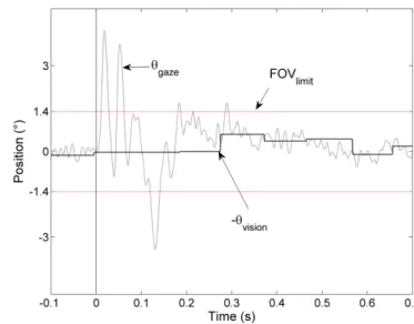
Fig. 8. Gaze orientation (θgaze) compared with the gaze orientation relative
to the target (θvision) during the second second thump given to the robot in
Fig.6. The two horizontal red lines delimit the field of viewFOVlimit (±1.4 deg) of the eye. A value of the gaze higher than ±1.4 deg means that the target has wandered out of the field of view. The duration of this “lost target” phase is so short (50ms, i.e. twice shorter than the vision refresh period) that it does not impair gaze stabilization.
perturbation is entirely rejected by both the VOR and the visual feedback loop.
As shown in Fig. 7, the eye position θer counteracts the robot’s position θheading quasi immediately thanks to the high speed dynamics of the eye’s orientation feedback control system GCS based on the fast VCM actuator. The eye’s rotation is fast enough to hold the gaze θgaze locked onto the target. Measurement of the robot’s gaze (θgaze) was not directly accessible (it would have required, e.g., a magnetic search coil or an eye tracker). The gaze was therefore calculated according to its definition (see Fig.2)
θgaze= θheading+ θer (3) Figure8shows that the thumps given to the robot’s body were so severe that the contrasting target (a white-dark edge) transiently wandered out of the small, ±1.4 deg field of view of the eye. Yet the robot does not get flummoxed by this situation. The contrasting target keeps being “seen” by the eye (see the θvision signal), because the time during which the target is led astray of the visual field (50ms) is shorter than the visual scanning refresh period of the eye (100ms).
VI. CONCLUSION
We described the principle and implementation of a minia-ture, tethered aerial platform equipped with a one-axis, ultra-fast and accurate gaze and heading control system inspired by highly proficient, long existing biological systems. The role played by the overall control system is to hold the line-of-sight of the eye (i.e., the gaze) stabilized onto a sharp contrast edge - as do flies between two saccades [4] - in spite of the disturbances that may affect the body (carrying the eye). This is achieved via two processes, a GCS and a
heading control systemHCSthat are largely interactive (Fig.
5). The GCSitself merges two reflexes:
• a slow but accurate Visual Fixation Reflex (VFR) that copes with long-lived (i.e., "DC") fixation
• a fast Vestibulo-Ocular Reflex (VOR) that copes with transient robot’s angular perturbations.
TheHCSreorients the robot’s heading in the same direction as the gaze, a process that takes a relatively long time (0.6 seconds), due to the relatively large body inertia (Fig.7).
We paid particular attention to testing the robustness of the control system by recording the eye’s and robot’s reactions to severe torque perturbations applied to the body. Using a custom-made "slapping machine", we showed that once destabilized by a nasty thump given to its body, the robot:
• keeps its gaze fixating the contrast edge, despite the small visual field of the eye
• reorients its heading actively until its catches up with the gaze direction (Figs. 6,7,8)
A highlight of this study is that the gaze itself is the fundamental (Eulerian) reference, about which any motor action (orienting the "eye in robot" and the "robot in space") is based.
This study considerably extends the scope of a former study in which we had realized a gaze control system endowed with aVOR, without showing its use onboard any robotic platform [22]. Besides, we now introduced a novel oculomotor servomechanism based on a VCM and a Hall sensor. The dynamics of this position servo is so high that it is able to bring the gaze to a new position in 12ms, i.e., much faster than a saccade in the human eye (Fig.4).
The two control systems (Heading Control System (HCS) and Gaze Control System (GCS)) that we presented here are largely intertwined and interact strongly. We have shown that theHCSis actively coupled with theGCSby receiving as inputs θer (as measured by the Hall sensor) and Ωheading (as measured by the rate gyro). Even though the eye is mechanically uncoupled from the robot’s body, theGCS is passivelycoupled to the HCSdue to the fact that the robot “carries” the whole oculomotor system (which means that the heading can disturbs the gaze). The active and passive couplings between the two control systems make the high performances of the robot’s heading control system (HCS) directly related to the high performances of the gaze control system (GCS). In other words, the faster the gaze stabilizes, the faster the heading will stabilize ; the more accurate the gaze, the more accurate the heading.
Our lightweight and robust gaze control system can be useful for the guidance of manned and Unmanned Air Vehicule (UAV), of Autonomous Underwater Vehicle (AUV), and particularly for Air Vehicle (MAV) and Micro-Underwater Vehicle (MUV), which are particularly prone to disturbances that may originate from fast pitch variations, wing-beats (or body undulations or fin-beats), wind gusts (or water streams), ground effects, Vortices, and all kinds of unpredictable aerodynamic (or hydrodynamic) disturbances.
Biological systems teach us that such disturbances are better compensated for early on by implementing a visuo-inertial gaze stabilization system that will yield a reference for heading stabilization. Anchoring the gaze on a feature of the environment provides a drift-free reference with respect to the world.
ACKNOWLEDGEMENTS
The authors acknowledge the assistance of M. Boyron for the design of the miniature electronic boards including the piezo driver, the EMD and the control systems. We thank F. Paganucci and Y. Luparini for their help with the mechanical construction of the eye, F. Ruffier and J. Serres for fruitful discussions and comments on the manuscript. This work was supported by CNRS, University of the Mediterranean and the French National Agency for Research (ANR, RETINAE project). APPENDIX Hgyro(s) = Kg (τ2s+ 1) (τ1s+ 1) With τ1= 4.3 ∗ 10−3s , τ2= 1897.5s and Kg= 2.27 ∗ 10−6 ˆ H−1 gyro(s) = Kginv (τ5s+ 1) (τ6s+ 1) With τ5= 3.68 ∗ 10−3s , τ6= 2.31s and Kginv= 606.5 Heye(s) = Ke (τ4s+ 1) (τ3s+ 1) With τ3 = 18.7 ∗ 10−3 s , τ4= 0.5 ∗ 10−3s and Ke = 226.3 ∗ 0.9 Grobot(s) = Krob 1 W 2r s2+2 ζr Wrs+ 1 With Wr= 17.96 rad s−1, ζr= 0.595 and Krob= 3.74 Kr= 6 Pure gain
Crobot(s) = 3.7 ∗ 10−6 Pure gain
CV OR(s) = ˆHgyro−1(s) Heye−1(s)
Cv(s) =K0s With visual sampling rate Tsc= 0.1s
and K0= 0.0574 Geye(s) = (τ7s+ 1) τ82s2+ 2 τ 8ζeyes+ 1) With τ7= 484 ∗ 10−6s, τ8= 26 ∗ 10−3s and ζeye= 0.27 CPD(s) = KPD (τ9s+ 1) (τ10s+ 1) With τ9= 9.65 ∗ 10−3s , τ10= 1.65 ∗ 10−3 and KPD= 0.8 CLP(s) = 1 (τLPs+ 1) With τLP= 769 ∗ 10−6s CPI(s) = KPI (τPIs+ 1) τPIs With τPI= 0.015s and KPI= 2.2 Fs(s) = 1 1 W 2ns 2+2 ζn Wns+ 1
With Wn= 200rad s−1and ζn= 0.9
REFERENCES
[1] R.Kern and D.Varjù, “Visual position stabilization in the hummingbird hawk moth, macroglossum stellatarum l.” J Comp Physiol A 182, pp. 225–237, 1998.
[2] N.Boeddeker, R.Kern, and M. Egelhaaf, “Chasing a dummy target: smooth pursuit and velocity control in male blowflies,” in Proc. R. Soc. Lond.B 270, 2003, pp. 393–399.
[3] R.M.Olberg, A. Worthington, and K.R.Venator, “Prey pursuit and interception in dragonfly,” J Comp Physiol A186, pp. 155–162, 2000. [4] J. H. V. Hateren and C. Schilstra, “Blowfly flight and optic flow. ii. head movements during flight,” J. Exp Biol, vol. 202, pp. 1491–1500, 1999.
[5] R. Hengstenberg, “Mechanosensory control of compensatory head roll during flight in the blowfly calliphora erythrocephala meig,” J. Comp Physiol A, vol. 163, pp. 151–165, 1988.
[6] T. Yamaguchi and H. Yamasaki, “Velocity based vestibular-visual integration in active sensing system,” in Proc. IEEE Intern. Conf. on Multisensor Fusion and Integration for Intelligent System, Las Vegas, USA, 1994, pp. 639–646.
[7] T. Shibata and S. Schaal, “Biomimetic gaze stabilization based on feedback-error learning with nonparametric regression networks,” Neu-ral Networks, vol. 14, pp. 201–216, 2001.
[8] F. Panerai, G. Metta, and G. Sandini, “Learning visual stabilization reflexes in robots with moving eyes,” Neurocomputing, vol. 48, pp. 323–337, 2002.
[9] A. Lewis, “Visual navigation in a robot using zig-zag behavior,” in Proceedings of Neural Informations Processing Systems (NIPS), 1997, pp. 822–828.
[10] P. Viola, “Neurally inspired plasticity in oculomotor processes,” in Proceedings of Neural Informations Processing Systems (NIPS), 1989, pp. 290–297.
[11] X.Twombly, R.Boyle, and S.Colombano, Active Stabilization of Im-ages Acquired on a Walking Robotic Platform. G.Bebis et al. (Eds.), ISVC 2006, LNCS 4292, 2006, pp. 851–860.
[12] R. Wagner, I. W. Hunter, and H. L. Galiana, “A fast robotic eye/head system: Eye design and performance,” in Proc. of IEEE Engineering in Medicine and Biology Society, vol. 14, 1992, pp. 1584–1585. [13] N. J. Strausfeld, H. S. Seyan, and J. J. Milde, “The neck motor system
of the fly calliphora erythrocephala. 1. muscles and motor neurons,” J. Comp. Physiol, vol. A 160, pp. 205–224, 1987.
[14] E. L. Keller, “Gain of the vestibulo-ocular reflex in monkey at high rotational frequencies,” Vis. Res., vol. 18, pp. 311–115, 1978. [15] M. Huterer and K. E. Cullen, “Vestibuloocular reflex dynamics during
high-frequency and high acceleration rotations of the head on body in rhesus monkey,” J Neurophysiol, vol. 88, pp. 13–28, 2002.
[16] R. W. Clifford, P. C. Know, and G. N. Dutton, “Does extraocular mus-cle proprioception influence oculomotor control ?” Br. J. Ophtalmol, vol. 84, pp. 1071–1074, 2000.
[17] T.Preuss and R.Hengstenberg, “Structure and kinematics of the proster-nal organs and their influence on head position in the blowfly cal-liphora erythrocephala meig,” J Comp Physiol A 171, pp. 483–493, 1992.
[18] A. Paulk and C. Gilbert, “Proprioceptive encoding of head position in the black soldier fly, hermetia illucens (l.) (stratiomyidae),” The Journal of Experimental Biology, vol. 209, pp. 3913–3924, 2006. [19] E. Liske, “The influence of head position on the flight behaviour of the
fly, calliphora erythrocephala,” J. Insect Physiol, vol. 23, pp. 375–179, 1977.
[20] S. Viollet and N. Franceschini, “Visual servo system based on a biologically-inspired scanning sensor,” in Sensor fusion and decen-tralized control in robotics II, SPIE, vol. 3839, Boston, 1999, pp. 144–155.
[21] ——, Super-accurate visual control of an aerial minirobot, in: Au-tonomous Minirobots for Research and Edutainment AMIRE. Pad-derborn, Germany: U. Ruckert, J. Sitte and U. Witkowski (Eds), 2001. [22] ——, “A high speed gaze control system based on the vestibulo-ocular reflex,” Robotic and Autonomous System, vol. 50, pp. 147–161, 2005. [23] N. Franceschini and R. Chagneux, “Repetitive scanning in the fly compound eye,” in Gottingen Neurobiol. Conf., Gottingen, 1997, p. 279.
[24] S. Viollet and N. Franceschini, “Biologically-inspired visual scanning sensor for stabilization and tracking,” in Proceedings of IEEE IROS’99, Kyongju, Korea, 1999, pp. 204–209.
[25] G. Westheimer, Visual hyperacuity. Berlin: Ottoson, Sensory Physi-ology 1, Springer, 1981.
[26] R. M. Steinman, “Voluntary control of microsaccades during main-tained monocular fixation,” Sciences, vol. 155, pp. 1577–1579, 1967. [27] W. Becker, Vision and visual dysfunction (Vol 8). GR.H.S. Carpenter
(Ed) Macmillan Press, Ltd, 1991, ch. 5 : Saccades, pp. 95–137. [28] B. M. Chen, T. H. Lee, K. Peng, and V. Venkataramanan, Hard Disk
Drive Servo Systems 2nd Edition. Springer, Berlin, 2006.
[29] R. H. S. Carpenter, Movements of the eyes, 2nd edt. PION, London, 1988, ch. 2 : Vestibular eye movements.
[30] F. Panerai, G. Metta, and G. Sandini, “Learning vor-like stabilization reflexes in robots,” in ESANN’2000 Proceedings, Bruges,Belgium, April 2000, pp. 95–102.
[31] N. Strausfeld, Atlas of an Insect Brain. Springer-Verlag, Berlin, Heidelberg, 1976.
[32] S.Viollet, L. Kerhuel, and N. Franceschini, “A 1-gram dual sensorless speed governor for micro-air vehicles,” in proc. IEEE IROS’07, San Diego, United States, submitted.
[33] S. Viollet and N. Franceschini, “A miniature biomimetic gaze control system,” in proc. IEEE Int Conf on Robotics and Automation ICRA, New-Orleans, USA, 2004, pp. 504–510.