Actuation of Shape Memory Polymer using Magnetic Fields for
Applications in Medical Devices
By
Patrick Regan Buckley B.S. Mechanical Engineering
Massachusetts Institute of Technology, 2003
SUBMITTED TO THE DEPARTMENT OF MECHANICAL ENGINEERING IN
PARTIAL FULFILLMENT OF THE REQUIRMENTS FOR THE DEGREE OF MASTER OF SCIENCE IN MECHANICAL ENGINEERING
AT THE
MASSACHUSETTS INSTITUTE OF TECHNOLOGY JUNE 2004
Signature of Author:
Patrick Regan'uckley Department of Mechanical Engineering 2004 Certified by: U) Professor of Accepted by: Professor ol
MASSACHUSETTS INS TUE OF TECHNOLOGY
Gareth Mc i*y Mechanical Engi r&ing
Ain Sonin F Mechanical Engineering Graduate Officer
Actuation of Shape Memory Polymer using Magnetic Fields for
Applications in Medical Devices
By
Patrick Regan Buckley
Submitted to the Department of Mechanical Engineering on 21 May, 2004, in Partial Fulfillment of the Requirements for the Degree of Masters of Science in
Mechanical Engineering
ABSTRACT
A novel approach to the heating and actuation of shape memory polymer using dispersed
Curie temperature thermo-regulated particles is proposed. Such a material has potential applications in medical devices which are delivered via catheters. A variety of tests were performed to determine the feasibility of this new approach to shape memory polymer actuation. Calorimetry tests were performed to quantify heat generation of various Nickel Zinc Ferrite particles. Dynamic Mechanical Thermal Analysis (DMTA), tensile strain recovery tests, and Differential Scanning Calorimetry (DSC) were used to measure the mechanical effects of various particle volume contents and sizes on shape memory polymer. These tests suggest that the proposed method of actuation is very feasible, rapid heating can be achieved and the addition of particles up to 10% volume content has a minimal effect on the mechanical properties of the shape memory polymer.
Thesis Supervisor: Gareth Mckinley Title: Professor of Mechanical Engineering
Acknowledgments
This thesis was made possible by the help of a great number of people. I am grateful for all the help and encouragement I received from the team of researchers at the Lawrence Livermore National Laboratory, this includes but is not limited to Duncan Maitland, Tom Wilson, Melodie Metzger, Jane Bearinger, Brian Kelly and Ward Small. Other people
who contributed to the successful completion of this thesis in a less direct but just as important manner, by providing moral support and or shelter during my time in the "van down by the river" are Darcy Kelly, Shawn Graham, Kurt Herzog, and Patrick Riley. Mr. Riley was especially inspiring to me and I am lucky to have him as a friend.
My thesis advisor Prof. Gareth Mckinley deserves a huge thanks, he is one of the most
excellent teachers I have had and I was always amazed by his wisdom and cheered by his humor.
My family and friends, especially my mother, Judith Regan, and the very special Alexis
Dieter deserve a thank you. They are two of the best woman I know. Tom Truelove thanks for correcting my atrocious grammer, and always being ready to go to Anna's. Henry Gabathuler thanks for your legal advice, you are going to make a great patent lawyer. I know I am missing people in this acknowledgment so I will end by just thanking everyone I know, that should cover it. That's it, I am done!
Table of Contents
I
INTRO DUCTIO N... 101.1 Purpose... 10
1.2 Specific M edical Application: Strokes ... 14
1.3 Scope of Thesis ... 16
1.3.1 Review of Induction Heating in Previous Medical Applications ... 16
1.3.2 M agnetic M aterial Characterization and Review ... 17
1.3.3 Dem onstration of Inductive Heating... 17
1.3.4 M echanical Properties of Particle loaded SM P ... 18
2 Literature Review and Background... 19
2.1 Hypertherm ia ... 19
2.1.1 Therm oregulation and Curie Tem perature... 19
2.1.2 M edically Safe M agnetic Field Lim its ... 21
2.1.3 Field Generation... 22
2.2 M odes of M agnetically Induced Heating... 23
2.2.1 Hysteresis Loss ... 23
2.2.1.1 M agnetostatic Energy ... 29
2.2.1.2 M agnetocrystalline Anisotropy Energy ... 29
2.2.1.3 M agnetostrictive Energy ... 30
2.2.1.4 Dom ain W all Energy ... 30
2.2.1.5 Dynam ic Losses at Dom ain W alls... 32
2.2.2 Eddy Current Loss ... 35
3 M aterials ... 37
3.1 Shape M em ory Polymer and Sam ple Preparation ... 37
3.2 N ickel Zinc Ferrite Particles ... 40
4 Inductive H eating Tests... 45
4.1 Equipm ent and Field Strengths ... 45
4.2 Testing Procedure ... 48
4.3 Test Results... 52
4.3.1 Hysteresis Loss or Eddy Currents... 55
4.3.2 Field Strength... 56
4.3.3 Volum e Fraction ... 56
4.3.4 Particle Diam eter ... 58
4.3.5 M aterial... 60
4.4 Heating of Com plex Shapes... 62
5 M echanical Testing ... 69
5.1 D ynam ic M echanical Therm al Analysis... 69
5.1.1 Test Procedure ... 69
5.1.2 Test Results ... 71
5.2 Strain Recovery... 83
5.2.1 Test Procedure ... 83
5.2.2 Test Results... 85
5.3 Differential Scanning Calorimetry... 89
5.3.1 Test Procedure ... 89
6 Conclusion ... 95
6.1 Results O verview ... 95
6.1.1 Inductive Heating Results... 95
6.1.2 M echanical Test Results ... 96
6.2 Future W ork and Im provem ents ... 97
6.2.1 Inductive Heating... 97
6.2.2 M echanical Testing ... 99
6.3 Final Com m ents... 100
B ibliography ... 102
A ppendix A : H eating Curves... 106
A ppendix B : D M TA C urves ... 118
A ppendix C : D SC C urves ... 134
Table of Figures
Figure 1: Proposed method of inductive heating of shape memory polymer using
dispersed ferrom agnetic particles. ... 13
Figure 2: The embodiment of a clot extracting device which employs inductively heated shape memory polymer as a device material, red block represents a blood clot... 16
Figure 3: A 5x magnification of 1% by volume Nickel Zinc Ferrite particle loaded SMP m atrix ... 17
Figure 4: General form of ferromagnetic materials hysteresis loop... 26
Figure 5: Minor hysteresis loops with magnetization curve... 27
Figure 6: Illustration of a 180' domain wall (Snelling 1969). ... 31
Figure 7: Illustration of induced eddy current. (http://www.ndt-ed.org/EducationResources/CommunityCollege/EddyCurrents/Physics/mutualinductance. h tm ) ... 3 5 Figure 8: Mold used to make flat rectangular samples... 38
Figure 4.1: Ameritherm Nova IM Induction Heating unit with remote heat station, faraday cage, and heat exchanger. ... 46
Figure 4.2: Measured coil currents and log fit for extrapolation of currents out to power setting of 1000 W atts ... 47
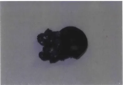
Figure 11: Example of melted calorimetry sample... 52
Figure 12: Volumetric Power Generation of magnetic particles vs. Volume Fraction of Particles, 12.2 M H z and 545.0 A/m ... 57
Figure 13: Volumetric Power Generation of magnetic particles vs. Volume Fraction of Particles, 12.2 M H z and 422.3 A/m ... 57
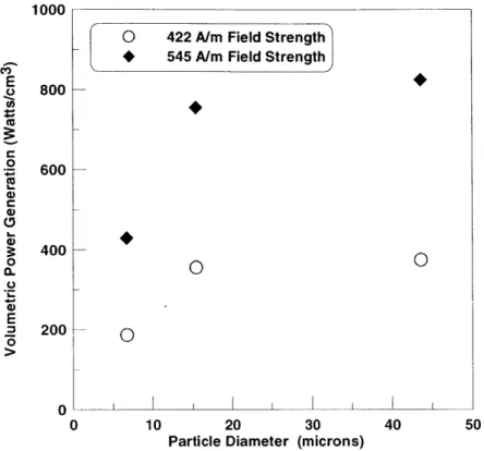
Figure 14: Particle Diameter vs. Volumetric Power Generation for 10% volume content C2050 exposed to a 12.2 MHz, 422.3 A/m, and 545.0 A/m magnetic field... 59
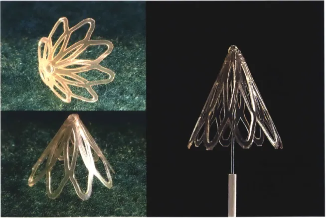
Figure 15: Flower shape tested in infrared thermal imaging heating experiment. ... 63 Figure 16: Actuation of SMP flower shape device with 10% volume fraction of 43.6pm particle diameter C2050 magnetic material. 12.2 MHz at 400 A/m applied magnetic field.
Figure 17: Flat SMP flower with 10% volume fraction of 43.6pm particle diameter
C2050 magnetic material. 12.2 MHz at 400 A/m applied magnetic field... 66
Figure 18: SMP foam with 10% volume fraction of 43.6pm particle diameter C2050 magnetic material. 12.2 MHz at 400 A/m applied magnetic field... 67
Figure 19: TA ARES- LS2 rheometer, with sample loaded for testing... 70
Figure 20:DMTA test results for 5% volume content, 43.6pm particle diameter C2050 loaded SMP illustrating G" maximum and tan (delta) maximum to the left and right of glass transition region on dynamic storage modulus curve. Vertical lines indicate the Tg values found at the G" and tan (delta) peak values... 72
Figure 21: Glass transition temperature vs. particle volume content, illustrating the effect of particle volume fraction and particle size on the Tg of SMP... 74 Figure 22: Rubbery dynamic storage modulus vs. particle volume fraction, illustrating increasing SMP rigidity in the rubbery region with increasing volume fraction of
p article s... 7 6
Figure 23: DMTA test results illustrating the effect of 25'C cure time on the mechanical properties of S M P . ... 77
Figure 24: Glassy dynamic shear storage modulus vs. particle volume fraction,
illustrating increasing SMP rigidity in the rubbery region with increasing volume fraction o f p articles... 8 1
Figure 25: Tensile testing setup, LOVE Control model 2600, and thermo-couple... 85 Figure 26: Stress vs. strain plot of tensile strain recovery test, 5% particle volume
content, 43.6pm particle size, and C2050 particle material, red line represents slope that Young's m odulus was calculated from ... 86
Figure 27: DMTA dynamic shear storage modulus, G', compared with tensile test Young's modulus, E, for increasing volume content of particles. Magnetic material
C2050 with 43.6pm diameter dispersed particles... 88
Figure 28: DSC test curve for 1% volume content C2050 SMP, 6.71pm particle diameter.
... 9 0
Figure 29: Particle volume fraction vs. glass transition temperature. DMTA and DSC calculated T. for C2050 magnetic material particle diameter 6.71gm dispersed in SMP.92 Figure 30: Particle volume fraction vs. glass transition temperature. DMTA and DSC calculated Tg for C2050 magnetic material particle diameter 43.6pm dispersed in SMP.92
Figure 31: Particle Diameter vs. Tg for DMTA and DSC test method. 10% volume
List of Tables
Table 1: Comparison of SMP and SMA properties (Otsuka and Wayman 1998)... 11 Table 2: Magnetic and material properties of Nickel Zinc Ferrite used in sample
preparation. (* designates measurement taken at 40 oersted applied field strength)(' designates values which were measured by author and not provided by the manufacturer)
... 4 2 Table 3: Average diameter of ball milled and sorted powders as calculated using ImageJ
digital im age processing. ... 44 Table 4: Calculated value of magnetic field with corresponding power setting of power
su p p ly ... 4 8 Table 5: Composition of heating samples tested. ... 49 Table 6: Testing times and field strength, roman numerals represent the number of repeat tests perform ed at each setting and tim e ... 51
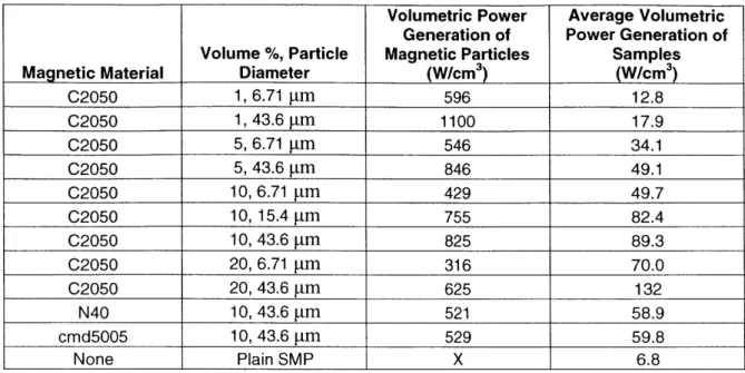
Table 7: Volumetric Power Generation of magnetic particles and Average Volumetric Power Generation of samples for 12.2 MHz and 422 A/m magnetic field... 54 Table 8: Volumetric Power Generation of magnetic particles and Average Volumetric Power Generation of samples for 12.2 MHz and 545 A/m magnetic field... 55 Table 9: Coercivity, remnance, and volumetric power generation for 43.6pm particle diameter and 10% volume content in SMP for C2050, cmd5005, and N40 ... 61
Table 10: DMTA results for the shift of Tg in SMP for varying particle volume fractions, particle size and particle m aterial. ... 73
Table 11: DMTA results, Glassy Modulus, Rubbery Modulus, and Storage Modulus R atio ... 7 5
Table 12: Strain recovery test results, Young's Modulus, Hysteresis Area, Max stress, R ecovered strain ... 87
Table 13: Glass transition as calculated from DSC tests, varying thermal history,
1 INTRODUCTION
1.1 Purpose
Shape memory polymers (SMP) are a class of polymeric materials that can be formed into a specific primary shape, reformed into a secondary stable shape, and then controllably
actuated by heating to recover its primary shape. This useful "shape memory" property makes SMP an attractive material for certain medical applications, ranging from stents to devices and tools which need to be delivered via catheter. Presently, minimally invasive catheter surgical techniques are limited by the functionality of the tools and devices which can be delivered inside the catheter. Devices must be small and or collapsible to fit inside the catheter, yet be useful once delivered to the site of interest. Utilizing SMP for medical devices such as stents or neurovascular surgical tools has great potential for creating new breakthrough treatment
options that are presently not available.
While other classes of thermally activated shape memory materials have been developed, shape memory alloys (SMA) (Schetky 1979) and shape memory ceramics (Swain 1986) being the two other major classes, SMP has a number of properties that make it better suited for certain medical applications. Firstly, shape memory ceramics have quite small recoverable strain and for this reason have not been used in any medical applications known to the author.
SMA have been adopted in a number of medical devices and would be the material SMP
would be competing with when the use of a shape memory material was necessary or seen as beneficial for a medical device, and for this reason these two materials will be compared.
The shape memory characteristics of SMA and SMP are vastly different, affecting the potential applications the materials are used in. Some of these key differences are illustrated in Table 1 (Otsuka and Wayman 1998).
Physical Properties Shape Memory Shape Memory
Polymer Alloy
Density (g/cm3) 0.9-1.1 6-8
Deformation (%) 250-800 6-7
Recovery temperature (C) 25-90 -10-100
Force required for deformation (kgf/ cm2) 10-30 500-2000
Recovery stress (kgf/ cm3) 10-30 500-2000
Table 1: Comparison of SMP and SMA properties (Otsuka and Wayman 1998)
As can be seen above, SMP is able to undergo deformations two orders of magnitude greater then SMA. SMA has the advantage of being able to generate a much larger force then SMP while actuating, demonstrated in the greater recovery stress. This indicates that SMA is a good material to use in applications where large forces are needed but small changes of shape are acceptable. SMP is better for applications where large changes in shape are desired but force generation is not as important. SMP also has some other advantages, such as it is cheaper and easier to program the primary and secondary shapes of SMP compared to SMA. SMP shapes can be programmed at temperatures -100 C, while for SMA shapes must be
programmed at higher temperatures, -400C. SMP can also be made in a biodegradable form (Lendlein and Langer) so that temporarily implanted devices can be degraded and absorbed by the body, eliminating the need for surgical retrieval. SMA does not give this option.
Currently there is much research into developing devices which take advantage of the unique properties of SMP. Some of the devices and research already done in this field includes vascular graft materials (Szycher, 1998), implant devices (Kusy and Whitley, 1994), catheters (LaFontaine, 1996), and microactuators (Benett et al., 1998).
The actuation temperature of SMP is determined by the soft phase material glass transition temperature of the material. This glass transition temperature (Tg) can be adjusted by changing the chemistry of the material which in turn affects the cross linking of the polymer chains. At the present time the major focus is on using SMP with a Tg of 55'C. This material has desirable stiffness at body temperatures and a Tg that is believed to be attainable without causing damage to the patient.
One of the major engineering challenges that stands in the way of using SMP in medical devices is the difficulty of heating devices to Tg inside the body. Presently SMP devices are heated using lasers or resistive heating elements(Maitland et al. 2002). These methods have the following disadvantages and limitations.
1. They require a power transmission line, be it a fiber optic or electrical wire. These
power transmission lines lose energy over their length, impede the flexibility of a catheter, require larger catheters to house them, and must be jointed to a device. It has been the author's experience that a devices joint can be the most complicated and failure prone part of a device.
2. The device geometry is limited by the heating mechanism. For example, if a laser is used, the ability of light to travel through the geometry of the device and be absorbed by the SMP severely limits the shape of a device.
3. Laser and resistive heating elements require feed back systems to ensure that
devices do not over heat.
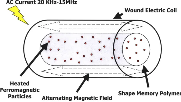
An alternative to using lasers or resistive heating elements is the use of inductive heating. This thesis proposes a novel method of SMP actuation which uses ferromagnetic particles dispersed in an SMP matrix as a means of induction heating. These dispersed
particles can be heated using alternating magnetic fields to cause heating and actuation of SMP. To the knowledge of the author this is the first proposed mechanism that will allow the use of inductive heating to cause SMP actuation. The method is illustrated in a general manner in the figure below. This figure is not to scale and it only serves to illustrate the principle of the idea.
AC Current 20 KHz-15MHz
Wound Electric Coil
Heated
Ferromagnetic
Particles Alternating Magnetic Field
Figure 1: Proposed method of inductive heating of shape memory polymer using dispersed ferromagnetic particles.
Further advantages of this approach are realized when the useful property of a
ferromagnetic material's Curie temperature (T) is understood and properly selected. T, is the temperature at which a ferromagnetic material becomes paramagnetic, losing its ability to generate heat via a hysteresis loss mechanism (Goldman 1990). By selecting a ferromagnetic particle material with a T, near the Tg of SMP, and by using particle sizes and materials which will heat mainly via a magnetic hysteresis loss mechanism instead of eddy current mechanism, it becomes possible to have a thermoregulation mechanism
which is an innate property of the material. The advantages of the inductive heating approach over the laser or resistive heating approaches are listed below.
1. There are no power transmission lines, heating and actuation is remote. This
allows smaller catheters to be used, increasing the access of a device to narrower vessels.
2. More complex device geometries are possible since even and consistent heating is provided throughout the SMP, and conduction lengths are very short due to the evenly dispersed particles.
3. The joint between the device and the power transmission line is eliminated,
simplifying and making a device more robust.
4. Thermoregulation can be provided by selecting the Curie temperature of the ferromagnetic particles, eliminating the need for thermoregulatory feedback systems.
1.2 Specific Medical Application: Strokes
The area of neurovascular surgery has a great need for devices that can function in the narrow and delicate vessels of the brain. In particular, there is a desperate need for a device to treat acute ischemic stroke, which is a stroke caused by a blockage of blood flow to the brain due to a lodged blood clot. 88% of all strokes in the US are of the ischemic variety (Maitland et al. 2002; A.H.A. 2003) and stroke is the third leading cause of death, with 163,538 deaths in 2001, and the leading cause of disability in the United States(A.H.A. 2003). Conservative estimates indicate that some 700,000 strokes occur annually and are expected to have an associated direct and indirect cost of 53.6 billion dollars in the year 2004 (A.H.A. 2003). Presently the only FDA approved treatment for
acute ischemic stroke is a blood thinning medication, tissue plasminogen activator (tPA). This drug is minimally affective, must be administered within 3 hours of the onset of stroke, is associated with increased risk of intracranial hemorrhaging, and, as a result, is administered in only 2-3% of acute stroke cases (Jonathan Hartmann 2003).
There can, however, be a window of 24 hours in which to restore blood flow before permanent brain damage is sustained (Maitland et al. 2002). This lengthy window allows time for surgical procedures and makes mechanical intervention to remove a clot an attractive option. At present there are few effective devices that exist to extract these clots. The tools and devices which do exist to perform clot extraction are relatively invasive and are limited to larger vessels such as the carotid arteries (4-5mm diameter). However, most blockages occur in the narrower (<3 mm diameter), and more deeply-seated vessels, such as the middle cerebral artery (Maitland et al. 2002).
It is the author's belief that the above mentioned advantages of an inductively heated shape memory polymer, mainly the possibility of the remote actuation of a
complex shaped device, and the possibility of using smaller catheters for device delivery, may offer the breakthrough that enables the design of a device which is small enough and savvy enough to perform clot extraction in the narrow and winding neurovasculature. If such a device is realized, it will provide a much more effective treatment option for people suffering an acute ischemic stroke than what is currently available. There is presently a group of researchers led by Duncan Maitland at the Lawrence Livermore National Laboratory who are working on the development of a clot extraction device made from SMP. One of the device embodiments is illustrated in the figure below.
(
Catheter
Magnetic Field Applied)
(Actuation)
(Extraction)
/
Figure 2: The embodiment of a clot extracting device which employs inductively heated shape memory polymer as a device material, red block represents a blood clot.
If the implementation of inductively heated SMP proves to be successful in a clot
extraction device, there are a host of other potential devices that may benefit from the material.
1.3 Scope of Thesis
1.3.1 Review of Induction Heating in Previous Medical Applications
A large body of research exists on the use of induction heating for hyperthermia
treatment. This is a treatment that attempts to heat cancerous tissue to above 42'C in an attempt to kill or weaken the diseased area. A review of the literature provides safety limits for magnetic field strengths and frequencies as well as providing some
recommendations for Curie temperature thermo-regulated materials and possible designs for induction coils and field generating machines.
1.3.2 Magnetic Material Characterization and Review
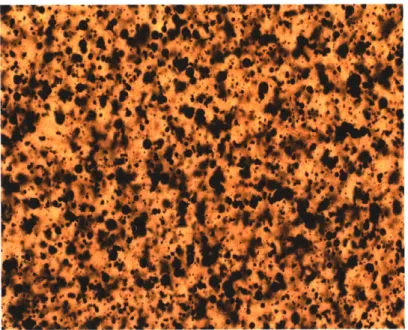
The different mechanisms of induction heating, hysteresis loss, and eddy current loss will be reviewed. This will aid in the future selection of a material that has a Curie temperature thermoregulation as described above. A number of possible materials will be suggested and three commercially available Nickel Zinc Ferrites will be experimented with. These three materials will be dispersed into SMP with varying particle sizes, ranging from 6.71-43.6 microns, and varying volume contents, ranging from 1-20% by volume magnetic material. The figure below shows an example of a particle loaded SMP matrix.
Figure 3: A 5x magnification of 1% by volume Nickel Zinc Ferrite particle loaded SMP matrix
1.3.3 Demonstration of Inductive Heating
Inductive heating of the SMP will be demonstrated and the affect of particle size and volume content on heating rates will be explored. The actuation of complex shaped devices using the inductive heating approach will also be shown.
1.3.4 Mechanical Properties of Particle loaded SMP
The effect of dispersed particles on the mechanical properties of SMP will be
explored. The thermo-mechanical effects on the material will be determined by Dynamic Mechanical Thermal Analysis (DMTA) and Differential Scanning Calorimetry (DSC). Large strain recovery will be tested with a tensile testing machine.
2 Literature Review and Background
2.1 Hyperthermia
A great deal of research has gone into the development of inductive heating for
applications in the field of Hyperthermia. Hyperthermia is a form of treatment that attempts to kill or weaken cancerous tissue by heating. A number of researchers have demonstrated the functionality of "thermal seeds", magnetic material in the form of cylindrical rods or particles which are implanted in the cancerous area and are then heated using an alternating magnetic field. While this application of inductive heating is very different than that proposed in this thesis, the research in this field has
demonstrated materials, field strengths, frequencies, and achievable heating rates using inductive heating in the body. Because the temperature range desired for hyperthermia treatment and SMP actuation overlap, hyperthermia attempts to generate temperatures
> 42'C (Stauffer et al. 1984) and most SMP devices can be actuated in the temperature range of 35'C T 80C, the research done in this field can be directly applied to inductively actuated SMP.
2.1.1 Thermoregulation and Curie Temperature
A key aspect of both hyperthermia and inductively actuated SMP is
thermoregulation. It is important to be able to set the maximum temperature of a heating device placed inside the body. This is important because excessive heating can damage body tissue and if it occurs in an SMP device it could cause melting of the plastic, an event that would most likely have adverse effects on health. Limiting the maximum temperature can be achieved with complicated and invasive feed back circuits but the simplest and most effective way of setting a maximum temperature with inductive
heating is by controlling the heating material's Curie temperature (T,) and ensuring that the material heats mainly via a hysteresis loss mechanism. T, is the temperature at which a ferromagnetic material transitions to a paramagnetic material (McCurrie 1994).
At T, the materials magnetic permeability drops to that of free space and the material no longer experiences hysteresis losses. This transition is an automatic temperature control built into the material. Field frequencies and strengths will not influence the Curie
temperature. The key to the success of inductively heated SMP is to find the optimum material for the heating particles. A number of materials with low Curie temperatures (40-100 degrees Celsius) are reviewed and proposed by Cetas in "A Ferrite Core /Metallic Sheath Thermoseed for Interstitial Thermal Ablation" (Cetas et al. 1998) . Among these materials are Ni-Si, Fe-Pt, and Ni-Pd alloys. A number of magnetic powders were also tested in "Inductive heating of ferromagnetic particles and magnetic fluids: physical evaluation of their potential for hyperthermia" (Jordan et al. 1993) of which Ni-Zn-Fe-O, Ba-Co-Fe-O, and Fe-O looked promising. Gray et al. also proposes a promising material in US patent US6,599,234B 1, "Heating of Magnetic Material by Hysteresis Effects" (Gray et al. 2003). This material is a substituted magnetite or ferric oxide crystalline lattice with a portion of the iron atoms substituted by one of the following; cobalt, nickel, manganese, zinc, magnesium, copper, chromium, cadmium, or gallium. Paulus et al. proposes a Palladium Cobalt alloy that also has a controllable Curie temperature in the range of 40-100 degrees Celsius in US patent US5429583 (Paulus and Tucker 1995).
2.1.2 Medically Safe Magnetic Field Limits
At increasing field frequencies and strengths, eddy current heating can be generated in body tissues. This safety concern places limits on field strengths and frequencies that can be used in medical applications. A number of researchers have made observations about this effect and developed safety limits. Atkinson, Brezovich, and Chakraborty in "Usable Frequencies in Hyperthermia with Thermal
Seeds"(Atkinson et al. 1984) developed a simple model of heat production per unit volume tissue. Simplifying a body torso to a cylinder, they derived that
P = (ffp o-, ,)2 ( H , 2 r 2, where P= heat production per unit volume tissue,
(W /) , O = electrical conductivity of the cylinder, ( ), p0,= magnetic
permeability of free space (1.257 x 10⁻⁶ H * m-') , Ho = magnetic field amplitude (A ),
f = field frequency (Hz), and r = radius from center of cylinder (m). It becomes
apparent from this equation that the heating produced in the tissue is proportional to the square of the product, Hf and r. This means that tissue farthest from the center axis of
the body would be subjected to the greatest heating rates. This being known Atkinson, Brezovich, and Chakraborty conducted experiments with numerous people and found that field intensities of 35.8 A/m at a frequency of 13.56 MHz could be tolerated for an extended period of time. They developed a safety limit of
Hof ; 4.85 x 10⁸ A -tuism. s for whole body exposure. It was also pointed out that
field strengths could be increased for extremities, such as the head or the arms since these portions of the body have smaller radii.
2.1.3 Field Generation
Inductively actuated SMP is only functional if it is exposed to the correct
frequency and magnitude magnetic field. While the generation of this field is not a part of this thesis it is important for the realization of its application. Research in the field of Hyperthermia has not been limited to just the design of heating elements, much research has also gone into the development of induction coils and field generating machines specially suited for use in medical applications and well suited for producing the magnetic fields needed to actuate the proposed SMP with dispersed ferromagnetic particles. A quick overview of the literature will give a sense of the applicability of this research towards the implementation of inductively actuated SMP.
Different induction coil designs are presented by Stauffer et al. in "Practical Induction Heating Coil Designs for Clinical Hyperthermia with Ferromagnetic
Implants" (Stauffer et al. 1994). This paper presents the field geometries and achievable field strengths generated by the different designs.
An inexpensive induction heating system for medical treatments is presented by Kimura and Katsuki in "VLF Induction Heating for Clinical Hyperthermia" (Kimura and Katsuki 1986) and Oleson gives a good overview of some basic coil designs in "A Review of Magnetic Induction Methods for Hyperthermia Treatment of Cancer" (Oleson 1984).
The possibility of using MRI machines for generating heating fields is also an attractive option, as many hospitals already have such equipment. This equipment uses an excitation RF magnetic field in the 30-60 MHz frequency (Jovicich 2004) that may possibly be used for heating magnetic particles. To the author's knowledge, no one has
investigated this possibility. More research needs to be done on the feasibility of this approach.
2.2 Modes of Magnetically Induced Heating
When a ferromagnetic material is exposed to an alternating magnetic field heat is produced; this is known as power loss (Zhen 1977). This heating is the result of a number of different microscopic mechanisms whose interactions are quite complicated and which have been studied and researched for most of the 2 0 h century and continue to be
researched today. Even with this rich history of research there has yet to be a reliable means of quantitatively predicting the macroscopic properties, including the power loss properties, of magnetic material from first principles (Wetzel and Fink 2001). It is still very useful to have at least a basic understanding of these microscopic mechanisms in order to understand what achievable heating rates are and to aid in the selection or possible creation of new materials that maximize heating and have the desired properties of Curie temperature and a loss mechanism which is mainly due to hysteresis instead of eddy currents. Although magnetic material development is largely a trial and error process, these basic principles can help in guiding this research in a more productive manner.
As described previously, the specific mechanisms that cause power loss can be grouped into two major categories: hysteresis loss, and eddy current loss. These two groups will be looked at separately.
2.2.1 Hysteresis Loss
A material's hysteresis loop is a measure of the hysteresis loss experienced by the
experienced in one magnetic reorientation, i.e. one cycle. Each time the magnetic
orientation of a material is switched, more heat is produced. It is important to understand that when referring to hysteresis and hysteresis loops in this thesis, it is the
independent definition that is used. Some researchers define hysteresis as including rate-dependant phenomenon such as eddy current loss (Bertotti 1998), and then make a distinction between rate-dependant and rate-independent hysteresis. The semantics and language of the magnetics research world are quite complicated and nuanced, but it has been the author's experience that it is more common in the literature to make a distinction between hysteresis and eddy current modes of heating rather then rate-independent and rate-dependent hysteresis. This being said, the rate independent definition of hysteresis and the methods used to measure hysteresis loops are somewhat artificial and tend to simplify intrinsically rate dependent phenomenon, as will be seen when the role of domain wall motion and magnetic rotation in hysteresis are discussed. The energy dissipated as heat via a single magnetic reorientation can be represented mathematically as (Zhen 1977).
Eh =f HdB (1)
If an alternating magnetic field is applied then the hysteresis loop is traversed
once every cycle and the power loss can be represented as the following (Wetzel and Fink 2001)
P = fE (2)
wheref is the frequency in Hertz. This equation is exact if the hysteresis loop is known for the processing parameters such as temperature, applied field amplitude, and frequency
(Wetzel and Fink 2001). However it is rare to find hysteresis curves for varying field frequency and temperature, and it is much more common to find DC saturation hysteresis loops, where the loop is measured under gradually varying field strengths at a constant temperature. The figure below depicts the common form of a DC hysteresis loop. The
size and shape of these loops depend on and vary widely with not only the above mentioned parameters, but also with the composition of the material, and the
metallurgical conditions of the material (Zhen 1977). Some hysteresis loops are narrow, wide, irregularly shaped, slanted, square, or some combination of these characteristics. As seen in the figure below some of the defining characteristics of a hysteresis loop are
Br, the remnance (units of Gauss, Tesla or (kg/s 2 A )), Bs, the saturation magnetization
(units of Gauss, Tesla or (kg/s 2 A)), He, the coercivity (units of Oersted or (A/r )),
and p , magnetic permeability (units of ( H/m ) or (rm * kg /s 2 A2). Br is the value of
induction which remains in the material after magnetic saturation and after the magnetic field has been reduced to zero (Goldman 1990). Bs is the maximum attainable intensity of magnetization per unit volume of a ferromagnetic material (Zhen 1977). H, is the value of the reverse field needed to reduce the induction of a magnetically saturated material back to zero (Goldman 1990). p is the ratio of the material's induction , B, to the
B
BBr
(B H)
Hc
Figure 4: General form of ferromagnetic materials hysteresis loop (modified from (Goldman 1990)). If a material is not forced to its saturation magnetization it will not trace its full
saturation hysteresis loop. Instead, it will trace what is known as a minor hysteresis loop.
The shape of this minor hysteresis loop tends to be similar to the shape of the saturation
loop but the area inside the loop is less. The figure below gives an example of a range of minor hysteresis loops inside a saturation loop. The curve which points A, B, C, and D lie along is known as the magnetization curve. It represents the induction which is induced in the material when it is magnetized from a magnetically unorientated state.
Figure 5: Minor hysteresis loops with magnetization curve (modified from (Goldman 1990)).
When you are attempting to heat a material via a hysteresis loss mechanism, it may be the case that you do not reach the full DC saturation hysteresis loop. This can be the case if the applied field is not strong enough to force the material to its saturation magnetization, and so the material traverses one of these smaller minor hysteresis loops. It can also be the case that temperature or the applied field frequency changes the shape of the
hysteresis loop from that of the DC saturation hysteresis loop, making the loop smaller. These affects can be taken into account by adding a correction factor, c, to the power loss equation. This new power loss equation is shown below.
To understand the mechanisms and properties which cause hysteresis heating, and determine the values of He, Br, B, and the size and shape of a materials hysteresis loop one must understand the concept of magnetic domains.
A macroscopic piece of ferromagnetic material is composed of numerous regions
known as magnetic domains. A domain consists of material which is magnetically saturated and aligned in the same direction (Zhen 1977). Domains are usually on the size order of microns and contain around 10'-10" atoms (Goldman 1990). Magnetic
domains are not the same thing as a material's microstructure; the size of a domain can be larger or smaller than the grain size of a material although it is rare to find domains larger than a material's grain structure (Bozorth and Metals 1959). The physical reason
magnetic domains are formed in a material is to minimize the material's free energy. An example of this free energy is illustrated by the potential energy contained in field lines that connect north and south poles of a piece of ferromagnetic material. These field lines tend to travel outside the material and have a certain potential energy associated with them. This potential energy is known as magnetostatic energy (Goldman 1990). By creating domains, the length of these field lines can be shortened, thus lowering the free energy of the material. Domains will continue to be formed in a material as long as they reduce the material's energy by more energy than it takes to form new domains.
A ferromagnetic material's magnetic energy can be classified into four major
categories: magnetostatic energy, magnetocrystalline anisotropy energy, magnetostrictive energy, and domain wall energy. Minimizing these four energies, as well as taking into account microstructural imperfections such as voids, non magnetic inclusions, and grain boundaries, will provide much information about the size, shape, and local variations in
domain structure which will in turn provide insight into a material's hysteresis loop (Goldman 1990). The domain structure of a material greatly affects which heating mechanisms are exhibited when a material is exposed to an alternating magnetic field. A brief overview of these four different forms of energy will be useful in understanding the forces involved in determining domain size and structure.
2.2.1.1 Magnetostatic Energy
Magnetostatic energy is the work which needs to be done in order to place magnetic poles in special geometric configurations (Goldman 1990). This energy can be calculated from a generalized equation found below (Goldman 1990),
Est =G Gdm. (4)
where G.= constant determined by geometry of domain, d=width of domain, and
M=magnetization intensity. From this equation it can be seen that magnetostatic energy decreases with the width of a domain. This is a driving force in making domains smaller and therefore increasing the number of domains in the same volume of material.
2.2.1.2 Magnetocrystalline Anisotropy Energy
Magnetocrystaline anisotropy energy is the greater amount of energy needed to create magnetic alignment in a 'hard' lattice direction rather than an 'easy' lattice direction. The 'easy' direction of magnetization may be an edge or a diagonal of the crystal unit cube (Goldman 1990). The anisotropy energy of the material can be lowered
by aligning magnetic moments (ferrimagnetic material) or magnetic spins (ferromagnetic
2.2.1.3 Magnetostrictive Energy
A small change in dimension occurs when a magnetic material is magnetized or
conversely when a magnetic material is stressed. The direction of magnetization will tend to align parallel or perpendicular to the direction of stress (Goldman 1990). The
dimension change which occurs during magnetization is on the scale of several parts per million, but the energy associated with this can have an effect on domain size and structure (Goldman 1990). The magnetostrictive energy can be represented mathematically by the following equation (Goldman 1990),
E ,itr = 3/2 Ao (5)
Where A = magnetostriction constant, and o =applied stress.
Inducing stresses in a material during processing by machining, grinding, or for ferrites
by firing can affect the magnetostrictive energy of a material and thus the domain
structure and power loss mechanism (Goldman 1990).
2.2.1.4 Domain Wall Energy
A domain wall is that portion of a domain structure where the magnetization
direction of one domain is gradually changed to the direction of a neighboring domain (Snelling 1969). In a 180' domain wall, the magnetic orientation direction changes 180 across the length of the domain wall, as illustrated in the figure below.
..-DOMAIH -80 WALL ---- DOMAIN
Figure 6: IDlustration of a 180 domain wall (Snelling 1969).
The arrows denote the direction of magnetic orientation. There are also domain walls which differ by less then 180' in magnetic orientation.
If the domain wall thickness is a, this being proportional to the number of atomic layers
in which the magnetic orientation changes from one domain to the other, there is a certain amount of energy stored in this transition due to spin interactions (Goldman 1990). This stored energy, known as exchange energy, can be represented mathematically as the following (Goldman 1990):
Ee = kT a (6)
where k=Stefan Boltzman constant, Tc=Curie temperature, kTc=thermal energy at the Curie point, and a= distance between atoms.
This shows that energy decreases as the width of the wall or the number of atomic layers in the wall is increased (Goldman 1990). There are, however, a number of other effects. If the material is crystalline, there is going to be a change in anisotropy energy as the magnetic orientation changes from an easy direction to a hard direction or vice versa across domain walls. Another effect is the magnetostrictive energy associated with the changing magnetic orientation across the domain wall. Accounting for these other effects, an equation which describes domain wall energy is the following (Goldman 1990).
EW = 2(kT/a)1/2 (K, + 32Ao./2)12 (7)
Where K, = Anisotropy Constant and As = saturation magnetostriction.
The typical values of domain wall energies are between 1-2 ergs/cm 2, with
domain wall widths between 10-6 cm for soft magnetic materials and up to I 04 cm for
hard magnetic materials (Goldman 1990). The form and organization of magnetic domains in a material will be dictated mainly by the minimization of the above four energies (Goldman 1990).
2.2.1.5 Dynamic Losses at Domain Walls
When a material is exposed to a magnetic field, its domains begin to experience a reorientating force. Domain walls begin to shift and move in response to the magnetic field. Figure 7 (Snelling 1969) illustrates a simplified rendition of the magnetization process. The lines in the diagram represent domain walls and the dots represent voids or imperfections in the material. In (b) and (c), the domain which is most closely aligned with the applied field begins to grow, bulging, pushing, and engulfing the other domains that are not aligned with the applied field, much like a membrane bulging due to an applied pressure. At the lower field strengths the domain walls remain pinned by voids and imperfections in the material, preventing complete domain alignment. These initial domain movements are largely reversible and are restricted by the stiffness of the domain walls. In (d) we see what happens as the field strength is increased and the domain walls experience enough pressure to jump past voids and imperfections. These jumps are irreversible and are known as Barkhausen jumps. These are what cause hystereses heating in multi-domain ferromagnetic materials (Zhen 1977). In (e) and (f) we see the processes of domain rotation, where the orientation of the domain rotates and aligns with
the applied field. This magnetic rotation process tends to be reversible. At this point, the material is said to be saturated, and no further increase in magnetization is possible.
yo * ON 0M
H H H
(a) (b) (c)
P0M H PoM H P M
(d) H H H
Figure 7: Simplified representation of domain boundary movement during magnetic reorientation (Snelling 1969).
This illustration is a simplified version of what happens in reality, but it gives a good overview of the basic role domain wall motion and magnetic rotation plays in the hysteresis power loss of multi-domain ferromagnetic material. It also gives some insight into how domain shapes and structures can influence the quantitative value of power loss.
The time scale that domain wall motion and magnetic rotation occur on are finite and thus the losses associated with them have some dependence on the rate at which the external field is applied. This is what was meant in section 2.2.1 when it was mentioned that hysteresis is inherently rate dependant.
At very high frequencies the material does not have time to respond to applied fields, and so does not fully magnetize (Wetzel and Fink 2001). This leads to different loss characteristics, which will be called low amplitude domain wall losses, since domain
wall motion is literally diminished in amplitude. It is conjectured that since the domains are not given enough time to fully reorientate, and undergo all the Barkhausean jumps at the higher frequencies, that heat generation from domain wall motion should be
diminished at increasing frequencies. However, at a critical frequency a material enters a state of magnetic resonance, where low amplitude losses are maximized (Wetzel and Fink 2001). It is not known, and it is beyond the scope of this thesis, to determine whether the resonant low amplitude domain wall losses are comparable to the lower frequency domain wall losses, but it is something to keep in mind for future research. This magnetic resonance usually occurs somewhere between 100 MHz and 10 GHz
(Wetzel and Fink 2001), and so is far above the frequencies used in this thesis.
Another interesting and potentially important change in loss mechanism occurs as particle sizes approach the size of single domains. In this case, typically reversible
processes can become irreversible. For example, in single domain ellipsoidal particles it has been observed that hysteresis losses are generated solely by a magnetic rotational mechanism (Zhen 1977). The drastic difference in the power loss behavior of single domain or sub-domain size particles and multi-domain size particles is something that should be kept in mind when selecting the particle size of material that is to be used for inductive heating applications.
It is beyond the scope of this thesis to discuss the specifics of domain wall motion and magnetic rotation, but for further information on these topics I refer the reader to references (Magana et al. 1986), (Lin et al. 1984), (Escobar and Valenzuela 1983), (Kittel
2.2.2 Eddy Current Loss
An electrically conductive material placed in an alternating magnetic field has alternating electrical currents induced within it (Wetzel and Fink 2001). The resistance to the flow of electrical currents through the material leads to the production of heat due to Joule (resistive) effects, and this is known as eddy current loss (Wetzel and Fink 2001). An illustration of how these eddy currents are induced to flow is illustrated in the figure below.
Coil's
Coil magnetic field
Ed dy currents
Conductive Material
Figure 8: Illustration of induced eddy current.
(http://www.ndt-ed.org/EducationResources/CommunityCollege/EddyCurrents/Physics/mutualinductance.htm)
Using Faraday's law, assuming a sinusoidally varying magnetic field and a spherical material geometry of diameter D0,Wetzel, in "Feasibility of Magnetic Particle
Films for Curie Temperature-Controlled Processing of Composite Materials" derives the following equation to describe the power loss associated with eddy currents (Wetzel and Fink 2001),
-(7yfB,D,)2
P - ~02 (8)
20po
where p. is the material's resistivity (ohm-meter), Bp is the field amplitude (Tesla),
f
is the field frequency (Hz), and Pe the volumetric power dissipation (W/m3).The eddy current heating mode is not controlled by the Curie temperature of the material because the loss mechanism is caused via the Joule heating caused by the flow
of electrical currents. If an electrically conductive material is heated above its Curie
temperature, it will still heat via an eddy current loss mechanism because the material is still electrically conductive, thus offering no Curie point thermoregulation. For this
reason it is desirable to minimize the eddy current heating mechanism of the heating particles dispersed in the SMP. As can be seen from the above equation, reducing the particle diameter and increasing the material's resistivity will reduce the magnitude of the
eddy current losses. It may not be possible to completely eliminate eddy currents, but if
they are minimized so that they only contribute a small fraction of the energy for heating,
with the majority of the energy for heating being generated by a hysteresis loss
mechanism, the advantages of the Curie temperature thermoregulation can still be realized.
3 Materials
3.1 Shape Memory Polymer and Sample Preparation
The SMP material used was an esterbased thermoset polyurethane, MP 5510, purchased from Memry Corp., distributor for Mitsubishi Heavy Industries, Ltd. One of the major reasons this class of SMP was used is that polyurethanes are generally
biocompatible, making them particularly well suited for medical applications involving internal short-term use (Lamba et al. 1998). The material was supplied in a two part liquid system consisting of a resin (A) and a hardener (B).
Because certain factors in the environment, such as air humidity and room temperature, were not controlled during sample preparation, these parameters were recorded so that their potential affects could be identified. All prepared samples were stored in a desicator to ensure a consistent dry storage environment. No significant effects on the mechanical properties of SMP due to the moderate changes in room humidity
(32%-56%) or room temperature (22 C-24 C) between sample preparations were noticed.
Two types of sample geometries were prepared, a cylindrical rod for DMTA testing, and a flat rectangular sample for recovered tensile strain testing. The heating samples were also obtained from these flat pieces by using a 9.52mm circular punch to make disc shaped samples that would fit inside a test tube. It is worth noting that attempts were made to use the flat rectangular samples for DMTA testing, but difficulty with test repeatability was encountered. The cylindrical rod samples yielded more repeatable DMTA test results. A picture of the mold used to make these flat rectangular samples is shown in the figure below. This mold had two levels allowing 12 samples to be made in one molding cycle.
Figure 9: Mold used to make flat rectangular samples.
The cylindrical rod samples were prepared by drawing SMP into a Iml Becton Dickinson tuberculin syringe and allowing it to harden in this form. The sample was then recovered by cutting the ends off the syringe and pulling the hardened SMP rod out. These samples had a diameter between 4.65mm and 4.70 mm. The flat rectangular samples were prepared using the mold pictured above. The mold allowed four different types of samples to be prepared in one molding run and was designed so that three of each sample type were molded at once. This allowed a total of 12 samples to be made in one molding run, a molding run being one curing cycle at 80'C. The samples had the following geometry: width of 12.5 mm, thickness of 1mm, and length of 80mm. Manufacturer recommended procedures were used when preparing samples. The procedure used was as follows:
2. Components were then allowed to cool to room temperature while being stored in a desicator to ensure a dry environment.
3. Mold surfaces were cleaned using acetone and were treated with one of the
following release agents: DuPont FEP solution with fluropel PFC 801 A additive, or TFE MS-122V Teflon spray from Miller Stevenson. After this treatment the mold was dried under vacuum in an oven for one hour at 80'C under vacuum. After this drying the mold was reassembled and set aside.
4. If a sample called for the addition of magnetic particles, they were added to component B and mixing was performed by hand using a mixing stick, a vortexer
machine, or a combination of these two techniques.
5. Components A and B were mixed together in the following ratio, A:B 2:3 by weight, using the same method as above. It should be noted that this ratio was calculated before the addition of magnetic particles, so the weight of particles did not factor into this ratio.
6. The mixture was degassed under a vacuum for approximately one minute or until
bubbling had subsided.
7. The mixture was then poured into a syringe and immediately injected into the
mold until excess poured out of the relief ports, or was drawn into lml Becton Dickinson tuberculin syringes.
8. The SMP began to harden in about 3 minutes time, making it necessary to move
quickly when mixing and injecting the SMP mixture.
9. After injection, the samples were allowed to sit at room temperature for a
10. The molds were then placed in an oven and cured at 80C for a minimum of 4
hours.
3.2 Nickel Zinc Ferrite Particles
Ferrites are an attractive class of material for Curie temperature thermoregulated inductive heating. As mentioned previously, it is important to maximize hysteresis losses while minimizing eddy current losses in order to ensure a thermoregulation set by the Curie temperature. Ferrite's very high resistivity, on the order of 106 to 1010 ohm-cm,
helps to minimize eddy current heating (Zhang 2003). Ferrites also have other attractive qualities such as environmental stability, a wide range of material compositions and magnetic characteristics, and an adjustable Curie temperature through Zn substitution (Zhang 2003). This last quality of an adjustable Curie temperature is illustrated below in the below figure for a nickel zinc ferrite material.
400 300 E a) 200 -100 F-0.4 0.5
Figure 10: Effect of Zn substitution on the
0.6 0.7 0.8
x, Ni1.,ZnFe2O4
Curie temperature of NiZn ferrite (Zhang 2003).
Equation for Linear Fit:
Y = -716.3915979 * X + 661.0776444
R2 = 0.99316
I I
The above figure illustrates how much a ferrite's Curie temperature can be affected by Zn substitution and how easy it is to predict a Curie temperature from the amount of Zn in the ferrite. There are other effects of adding Zn to a ferrite material that are not as easily pre-determined. An example of this is the change in a ferrite's magnetic coercivity. This property does not have a nice linear response to Zn substitution.
Three compositions of NiZn ferrite were used in this thesis. The composition of these materials was unknown but they were all obtained from Ceramic Magnetics Inc.. The three classes of material used were C2050, CMD5005, and N40. According to the manufacturer, C2050 and N40 were specifically designed for use in applications up to
1000 MHz in power supplies, linear amplifiers, UHF, and VHF. N40 was designed for
applications between 1-100 MHz in pulse applications, RF power amplifiers, current transformers for EMP, and deflection magnets for particle accelerators. The smallest particle size available from the manufacturer was said to have an average size of 50pm,
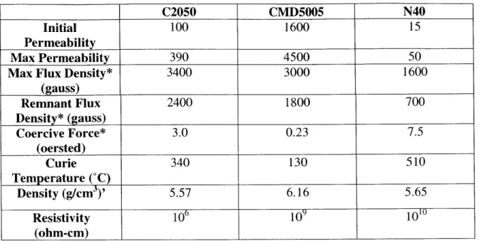
and was obtained from the 'fines' of the manufacturing process. Due to the processing technique these particles had a spherical shape to them. The following material properties were supplied by the manufacturer, with the exception of the densities, which were measured by the author using a standard volume displacement technique.
C2050 CMD5005 N40
Initial 100 1600 15
Permeability
Max Permeability 390 4500 50
Max Flux Density* 3400 3000 1600
(gauss) Remnant Flux 2400 1800 700 Density* (gauss) Coercive Force* 3.0 0.23 7.5 (oersted) Curie 340 130 510 Temperature ('C) Density (g/cm3)' 5.57 6.16 5.65 Resistivity 106 109 101 (ohm-cm)
Table 2: Magnetic and material properties of Nickel Zinc Ferrite used in sample preparation. (* designates measurement taken at 40 oersted applied field strength)(' designates values which were measured by author and not provided by the manufacturer)
A fourth material, magnetite (Fe304), also known as iron oxide, was obtained
from Nanostructered & Amorphous Materials inc., and also experimented with. The manufacturer claimed a particle size of 20-30 nm and a spherical particle shape. When attempts were made to disperse this material into SMP, two problems were encountered. One was that the SMP began to foam, making it impossible to make useful samples, and second, the particles did not appear to be the 20-30nm size which the manufacturer claimed. Using light microscopy to view the particles, it appeared that they had
aggregated into larger, irregularly shaped particles on the size scale of 10's of microns. Two techniques were employed to combat these problems. The first was to dry the powder in an attempt to eliminate all the moisture that may have been trapped in the material. It was hypothesized that this water may have been causing the SMP to foam. The material was spread out on a sheet and vacuum dried at 200C for 4 hours. This
was used to try and break up the particle aggregates, The dispersant used was
Disperbyk-116 from BYK Chemie. It appeared to have minimal effect and caused the SMP to
soften, which was undesirable. Due to time limitations the use of this material had to be abandoned. Future work needs to be done to see how this material might be used in SMP, as it shows promise as a heating material.
The NiZi ferrite material was prepared, dried and sorted according to the following procedure:
1. Material was sorted for 15 minutes using a WS tyler model RX-29 shaker and the following mesh screens: 53pm, 43pm, 25pm, 16pm, and 8pm pore sizes.
2. Some of the material larger then 53pm was ball milled for 5 hours using a United Nuclear 3 lbs. ball mill and 1.27cm diameter stainless steel balls. These balls were recommended by and purchased from Ceramic Magnetics inc., the manufacturer of the Nickel Zinc ferrite powder.
3. Ball milled material was vacuum dried at 200C for 4 hours. All other material
was vacuum dried between 80-90'C for at least 1 hour. The ball milled material was dried at this higher temperature because it exhibited a resistance to drying at the lower temperature.
4. After drying, the material was stored in a sealed glass jar inside a desicator. This was done to ensure a dry environment for all samples.
Particle size was determined by dispersing a small amount of powder in glycerol and mounting the suspended particles on a slide. Light microscopy was used to magnify the image by 200x and a digital photo was taken. A photo of a 1mm ruler dash under the same magnification was also taken in order to serve as a calibration distance. These