3D thermal analysis of a permanent
magnet motor with cooling fans
The MIT Faculty has made this article openly available. Please share
how this access benefits you. Your story matters.
Citation
Tan, Zheng et al. “3D Thermal Analysis of a Permanent Magnet
Motor with Cooling Fans.” Journal of Zhejiang University SCIENCE A
16.8 (2015): 616–621.
As Published
http://dx.doi.org/10.1631/jzus.A1400293
Publisher
Zhejiang University Press
Version
Author's final manuscript
Citable link
http://hdl.handle.net/1721.1/105913
Terms of Use
Article is made available in accordance with the publisher's
policy and may be subject to US copyright law. Please refer to the
publisher's site for terms of use.
3D thermal analysis of a permanent magnet
motor with cooling fans
Zheng TAN1, Xue-guan SONG2, Bing JI1, Zheng LIU1, Ji-en MA3,4, Wen-ping CAO†‡5,6 (1School of Electrical and Electronic Engineering, Newcastle University, Newcastle upon Tyne, NE1 7RU, UK)
(2School of Mechanical Engineering, Dalian University of Technology, Dalian 116024, China)
(3College of Electrical Engineering, Zhejiang University, Hangzhou 310027, China)
(4Department of Mechanical Engineering, University of California at Berkeley, Berkeley, CA 94720-1740, USA)
(5School of Electronics, Electrical Engineering and Computer Science, Queen’s University Belfast, Belfast BT9 5AH, UK)
(6Department of Electrical Engineering and Computer Science, Massachusetts Institute of Technology, Cambridge, MA 02139, USA)
†E-mail: w.cao@qub.ac.uk
Received Sept. 24, 2014; Revision accepted Feb. 12, 2015; Crosschecked July 20, 2015
Abstract: Overheating of permanent magnet (PM) machines has become a major technical challenge as it gives rise to magnet demagnetization, degradation of insulation materials, and loss of motor efficiency. This paper proposes a state-of-the-art cooling system for an axial flux permanent magnet (AFPM) machine with the focus on its structural optimization. A computational fluid dynamics (CFD) simulation with thermal consideration has been shown to be an efficient approach in the literature and is thus employed in this work. Meanwhile, a simplified numerical approach to the AFPM machine with complex configuration in 3D consisting of conduction, forced convection, and conjugate heat transfer is taken as a case study. Different simplification meth-ods (including configuration and working conditions) and two optimized fans for forced convection cooling are designed and installed on the AFPM machine and compared to a natural convection cooling system. The results show that the proposed ap-proach is effective for analyzing the thermal performance of a complex AFPM machine and strikes a balance between reasona-ble simplification, accuracy, and computational resource.
Key words: Axial flux permanent magnet (AFPM) machine, Computational fluid dynamics (CFD), Cooling fan, Motor drives, Thermal analysis
doi:10.1631/jzus.A1400293 Document code: A CLC number: U264.1
1 Introduction
In recent years, permanent magnet (PM) ma-chines have attracted much attention in various in-dustries, such as electric vehicles, wind generators, electric ships, and high-speed trains, due to their high torque density and high efficiency in compact pack-ages. With the ever-growing demand for high torque density and drive power, the thermal problems of PM machines have become increasingly studied and the
efficient analysis and design of cooling techniques for PM machines have become very important and necessary.
It is widely known that the performance of PM machines in many applications, including high-speed trains, is affected by overheating, which can easily cause magnet demagnetization, and degradation of the isolation materials and of motor efficiency. Therefore, it is very important to develop an effec-tive heat dissipation technique for PM machines. In this paper, a novel and special cooling system design for an axial flux permanent magnet (AFPM) machine is carried out as a case study. In the literature there has been much research on the electromagnetic
Journal of Zhejiang University-SCIENCE A (Applied Physics & Engineering) ISSN 1673-565X (Print); ISSN 1862-1775 (Online)
www.zju.edu.cn/jzus; www.springerlink.com E-mail: jzus@zju.edu.cn
‡ Corresponding author
ORCID: Zheng TAN, http://orcid.org/0000-0002-6957-7006; Wen-ping CAO, http://orcid.org/0000-0002-8133-3020
aspects of AFPM machines, but their thermal per-formance has not been fully investigated (Mellor et
al., 1991; Hendershot and Miller, 1994; Lee et al.,
2000; El-Refaie et al., 2004; Boglietti et al., 2005; Mezani et al., 2005; Dorrrell et al., 2006; Trigeol et
al., 2006; Yu et al., 2010; Wrobel et al., 2013;
Chong et al., 2014; Dong et al., 2014). For other types of electrical machines, there are four methods generally used for thermal analysis. These are the lumped parameter network method, the finite ele-ment method (FEM), the computational fluid dynam-ics (CFD) method, and the experimental method. The lumped parameter network method is widely used due to its fast prediction and reasonable simplifica-tion. However, to achieve accurate results, the model parameters such as convective heat transfer coeffi-cients, thermal contact resistances, and the properties of components have to be defined or assumed before the analysis, and some of these properties are diffi-cult or impractical to measure in reality. In compari-son, the FEM needs less experimental or empirical values for an accurate analysis and it can provide more details about localized temperature distribution. However, the FEM is usually used for conduction heat transfer problem rather than convection heat transfer and conjugate heat transfer problems, and that restricts its wide application for AFPM machines with air-forced cooling. The experimental method is the most effective method, but the test facilities re-quired can be costly and time-consuming. Therefore, for convection heat transfer analysis of AFPM ma-chines with air-forced cooling devices, the CFD method is chosen here because it can consider both conduction and convection phenomena, even though it usually takes a little more time and effort than the lumped parameter network and FEM.
This paper presents a 3D thermal study of an AFPM machine using CFD analysis. The heat source is obtained and defined based on physical experi-ments. Two kinds of fans for forced convection cool-ing are designed and installed on the AFPM machine without adding any cooling equipment. The results show that CFD is very efficient for thermal analysis of the AFPM machine at the design stage. The de-sign of cooling fans is helpful in lowering the tem-perature and avoiding overheating issues in the machine.
2 AFPM machine
The AFPM used in this study for thermal analy-sis is shown in Fig. 1. It is used for traction drive applications. There are three main components of the machine, of which the first is the rotor disc with 30 embedded permanent magnets, the second is the sta-tor with copper wires wound around a steel core, and the third is the casing supporting the rotor disc and the stator. The copper windings are bundles of indi-vidual wires of 0.5 mm diameter coated with a layer of insulation. Fig. 2 shows a simplified model in 3D,
Fig. 1 Photo of the AFPM
Fig. 2 Numerical model of the AFPM (a) CAD model; (b) CFD model
(a)
which considers the bundles as one non-individual body. The air enters through the cut-out on the cas-ing around the shaft, and flows out from the cut-out on the casing in the axial direction.
3 CFD modelling
The approach used for thermal analysis in this study is based on steady CFD analysis. As mentioned above, it involves both heat conduction and convec-tion transfer. To solve such a conjugate heat transfer problem with a high accuracy, 3D steady Reynolds-averaged Navier-Stokes equations and the energy equation are developed and numerically solved.
Some assumptions are required for solving the heat transfer problem. These are: (1) the flow is tur-bulent and incompressible, (2) the flow is steady-state, (3) buoyancy and radiation heat transfer are neglected, and (4) the thermo-physical properties of the fluid are temperature independent. Based on these assumptions, the governing equations (continu-ity, momentum, and energy equations) are estab-lished as follows: ( ) 0, i i u x (1) ( ) 2 3 , i j i j k ij j i j j i k i j j u u p u u u x x x x x x u u x (2) eff eff [ ( )] ( ) , i i ij E j j j u E p T u S x x x (3)
where ρ is the fluid density, ui and uj are the velocity
vectors in two perpendicular directions i and j, re-spectively, p is the static pressure, μ is the molecular viscosity, also referred to as the dynamic viscosity,
δij is the Kronecker delta function, E is the total
en-ergy per unit mass, SE is the energy generation rate
per unit volume, T is the temperature, u'i and u'j
rep-resent the velocity fluctuations, u ui is the Reyn-j olds stress, λeff is the effective thermal conductivity,
and (τij)eff is the deviatoric stress tensor. Since this is also a conjugate heat transfer problem, which in-volves heat conduction, the governing equation of the solid is also required:
s E 0, j j T S x x (4)
where λs is the thermal conductivity of the solid.
A 3D model is built to contain all the rig com-ponents and the cooling fan. Fig. 2a shows the sec-tional structure model with reasonable simplification and with addition of the cooling fan which does not exist in the original model shown in Fig. 1. Fig. 2b depicts the CFD model used for the thermal analysis of the AFPM based on the simplified structural mod-el in ANSYS CFX 14.0. The CFD modmod-el is verified in terms of grid size, turbulence model selection, and discretization schemes, and it encloses all compo-nents in an air cabinet by using solid-solid interfaces and fluid-solid interfaces. A total of four parts in-cluding the flow field (outside and inside) and struc-ture model are built and connected together. Taking advantage of symmetrical geometry, it is only neces-sary to develop a 1/24 model (30° in the symmetrical model) to reduce the computational burden, in which symmetrical boundary conditions instead of periodic boundary conditions are used in the cut planes, since the planar smooth surfaces of the rotor have less ef-fect on heat transfer even during high speed rotation. The effect of small fins installed along the diameter edge is ignored, because the air gap between the ro-tor and staro-tor is very small and its precise implemen-tation in the calculation is difficult. From a basic electromagnetic simulation, the total heat generated in the full model is 780 W at 2600 r/min (including winding copper loss and iron loss), so an approxi-mate estimation of heat generated at the stator and rotor can be made as shown in Table 1.
Table 1 Heat generated in the 1/24 model Component Volume (m3) Heat (W) Source (W/m3)
Stator 3.74×10⁻⁵ 16.25 4.34×10⁵
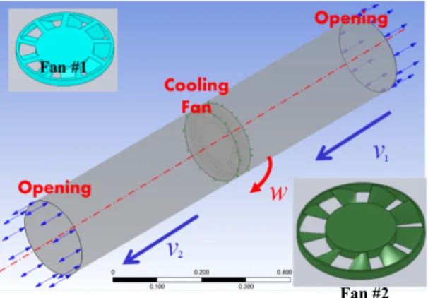
To optimize the cooling design, a comparative study is conducted for the AFPM machine under three conditions: no fan, fan #1, and fan #2. Fan #1 is an empirical design based on engineering experience, which is shown at the upper left corner of Fig. 3. Fan #2 with curved surfaces is optimized by aerodynamic study and is shown at the lower right corner of Fig. 3. The two have identical outer diameters and numbers of blades. For the model without a cooling fan, the inlet region in Fig. 2b is set as an opening boundary. In the case of the models with cooling fans, the open-ing boundary condition at the inlet region is replaced by a constant inlet air mass flow, which is calculated in terms of CFD simulation as shown in Fig. 3 and Table 2. This gives a straightforward way of estimat-ing the mass flow condition for the thermal perfor-mance of the AFPM machine, and it can be easily used for other similar CFD analyses without prior knowledge of the mass flow condition.
Grid quality and independence have been exam-ined to minimize their influence, where the grid of flow field has 462117 nodes, the casting model has 55574 nodes, and the rotor and stator models have 8577 and 1593 nodes, respectively. In addition, the standard k-ε turbulence model is used, and a scalable wall function is implemented over the solid walls.
Thermal energy instead of total energy is used to model the transport of enthalpy through the fluid domain due to the low speed flows through and around the machine. Automatic time step control is used and the convergence criteria are assumed to be satisfied if the root mean square (RMS) residual is lower than 1×10⁻⁵.
4 Analysis of CFD results
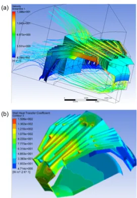
The thermal analysis is carried out on a 64-bit workstation, and each analysis takes about 3 h to converge. Fig. 4a plots the streamline through and around the AFPM with the cooling fan #1. It is found that 74.8% of the total mass flow pumped by the cooling fan flows outside the machine and the re-maining 25.2% of the total mass flow ventilates the inside space through the cut-out on the casting. It is evident that both the external air flow and the inter-nal flow play a significant role in heat dissipation. However, the wall heat transfer coefficient plot in Fig. 4b indicates that the external air flow provides the majority of the total heat dissipation as the exter-nal flow is much greater than the inside one on the disc surface. To enhance the total cooling perfor-mance, it is desired to design a better cut-out on the casing, which would have less pressure loss and thus allow more air flow through it to directly cool the inside surfaces.
Fig. 5 plots the temperature distribution on the three main components of the machine and the mid-dle plane between the stator and rotor discs, where the maximum temperature can be found at the stator at the side approaching the rotor. The contact surfac-es between the casting and stator play a significant part in the heat conduction, which leads to a tem-perature reduction in the stator. The temtem-perature dis-tribution on the middle plane illustrates the flow temperature and shows that, as expected, much heat is taken away by means of the cut-out on the casting.
Table 3 lists the minimum and maximum tem-peratures in each component with and without cool-ing fans. Fans #1 and #2 are efficient in decreascool-ing the temperature. In particular, the temperatures of the stator, rotor, and casting with fan #1 decrease by ap-proximately 150, 110, and 150 °C, respectively,
Table 2 Mass flow rate at three cooling conditions
Fan type Mass flow rate (kg/s)
2600 r/min 4600 r/min 6600 r/min
No fan No forced ventilation
#1 0.060 0.106 0.152
#2 0.128 0.227 0.327
Fig. 3 Simple cooling fan model for mass flow calculations
as compared to the machine without a cooling fan. The design with fan #2 has an even better cooling performance, resulting in a further 15 °C reduction compared to fan #1.
5 Conclusions
In this study, the CFD method has been used to investigate heat transfer in an axial flux permanent magnet machine and to optimize a cooling fan design. Some simplifications and assumptions are made to facilitate a numerical analysis, based on the steady CFD method, to predict the coolant air mass flow, velocity, and pressures outside and inside of the ma-chine and the temperature distribution of the mama-chine. The comparison results of the AFPM machine with-out a cooling fan and with two designs of cooling fans reveal that cooling fans are helpful in enhancing heat transfer and reducing the temperature of the ma-chine, and a good design of cooling fans based on aerodynamics is efficient and essential to avoid overheating problems. Further work will be set out to conduct extensive experimental tests on these prototypes.
References
Boglietti, A., Cavagnino, A., Staton, D.A., 2005. TEFC in-duction motors thermal models: a parameter sensitivity analysis. IEEE Transactions on Industry Applications, 41(3):756-763. [doi:10.1109/TIA.2005.847311]
Chong, Y.C., Echenique-Subiabre, E.J.P., Mueller, M.A., et
al., 2014. The ventilation effect on stator convective heat
transfer of an axial flux permanent magnet machine.
IEEE Transactions on Industrial Electronics, 61(8):
4392-4403. [doi:10.1109/TIE.2013.2284151]
Dong, J., Huang, Y., Jin, L., et al., 2014. Thermal optimiza-tion of a high-speed permanent magnet motor. IEEE
Transactions on Magnetics, 50(2):749-752. [doi:10.
1109/TMAG.2013.2285017]
Dorrrell, D.G., Staton, D.A., Hahout, J., et al., 2006. Linked electromagnetic and thermal modelling of a permanent Fig. 5 Temperature distribution of the machine (a) and
the middle plane at the air gap (b)
(b) (a)
Fig. 4 Air streamline (a) and wall heat transfer coeffi-cient (b) around the AFPM with fan #1
(a)
(b)
Table 3 Component temperature at three ventilation conditions
Fan type
Temperature (°C)
Stator Rotor Casting
Min Max Min Max Min Max
No fan 237.5 247.2 192.1 215.4 213.6 242.5 #1 86.8 92.5 78.6 80.5 80.5 87.6 #2 72.1 77.7 65.4 66.7 66.0 72.9
magnet motor. 3rd IET International Conference on Power Electronics, Machines and Drives, Dublin, Ireland, p.536-540. [doi:10.1049/cp:20060166]
El-Refaie, A.M., Harris, N.C., Jahns, T.M., et al., 2004. Thermal analysis of multibarrier interior PM synchro-nous machine using lumped parameter model. IEEE
Transactions on Energy Conversion, 19(2):303-309.
[doi:10.1109/TEC.2004.827011]
Hendershot, J.R., Miller, T.J.E., 1994. Design of Brushless Permanent Magnet Motors. Magna Physics and Oxford Science Publications, Oxford, UK.
Lee, Y.S., Hahn, S., Kauh, S.K., 2000. Thermal analysis of induction motor with forced cooling channels. IEEE
Transactions on Magnetics, 36(4):1398-1402. [doi:10.
1109/20.877700]
Mellor, P.H., Roberts, D., Turner, D.R., 1991. Lumped pa-rameter thermal model for electrical machines of TEFC design. IEE Proceedings B (Electric Power
Applica-tions), 138(5):205-218. [doi:10.1049/ip-b.1991.0025]
Mezani, S., Talorabet, N., Laporte, B., 2005. A combined electromagnetic and thermal analysis of induction motors.
IEEE Transactions on Magnetics, 41(5):1572-1575.
[doi:10.1109/TMAG.2005.845044]
Trigeol, J.F., Bertin, Y., Lagonotte, P., 2006. Thermal model-ing of an induction machine through the association of two numerical approaches. IEEE Transactions on
Ener-gy Conversion, 21(2):314-323. [doi:10.1109/TEC.2005.
859964]
Wrobel, R., Vainel, G., Copeland, C., et al., 2013. Investiga-tion of mechanical loss and heat transfer in an axial-flux PM machine. IEEE Energy Conversion Congress and Exposition, Denver, USA, p.4372-4379. [doi:10.1109/ ECCE.2013.6647285]
Yu, Q., Laudensack, C., Gerling, D., 2010. Improved lumped parameter thermal model and sensitivity analysis for SR drives. XIX International Conference on Electrical Ma-chines, Rome, Italy, p.1-6. [doi:10.1109/ICELMACH. 2010.5607746]