by
Dean Bedford, Jr. and Herbert LaGrange Wolfe
Submitted in Partial Fulfillment of the Requirements for the Bachelor of Science Degree in Mechanical Engineering
from the
Massachusetts Institute of Technology I1947
Acceptance:
Instructor in Charge of Thesis,
r am r r rr r __
.Cambridge, Mass. 16 January, 1947.
Professor Joseph S. Newell
Massachusetts Institute of Technology Cambridge, Massaohusetts.
Dear Sir:
A thesis entitled "Analysis of Japanese Aircraft Engine" is herewith submitted in partial fulfillment of the requirements for the degree of Bachelor of Science in Mechanical Engineering.
Respectfully,
/ /
The authors of this paper wish to thank
Profes-sor J. V. D. Eppes, their thesis advisor, for his
val-uable contribution of time and information which made
the completion of this paper possible. They also desire
to express their sincere appreciation of the aid and
contributions rendered by Professor C. F. Taylor, Pro-fessor W. A. Leary, Mr. Cyrus H. Kano, and the staff of the Sloan Laboratory. Thanks are also due to Mr. Stephen W. Plimpton for the use of the facilities of the Plimton photo Lab.
Contents
Page Purpose... 1 Introduction... ... 2 Body of Thesis.. ... *...* 3 Cylinder... 4 Valve Mechanism... ... 4Piston and Connecting Rod... 6
Crankshaft...*...*... 7
Supercharger and Induction System... 7
Injection System. ... 9
Discussion of Results... 14
Conclusions... ... o... 21
Suggestions for Future Investigation... 23
Appendix
Appendix
Appendix Appendix Appendix Appendix I - Engine Data II - Material Analysis III - Calculations IV ; GraphsV - Drawings and Photographs
It is the purpose of the authors of this paper to examine the design and constructional features of an experimental Japanese aircraft engine and to evaluate any new or unusual features found therein.
This subject has been selected since it lies in
the major field of study of the investigators and pro-vides an opportunity for them to put into practice the
theory learned in classroom work.
To the best knowledge of the authors there has been no previous work in this country on this design of Japanese aircraft engine. For this reason no data has
been available from other sources pertaining to this particular design.
Introduction
This paper is intended not as a detailed
descrip-tion of the design and construcdescrip-tion of the engine under
investigation, but rather as a preliminary survey of such a design, seeking to discover and evaluate any un-usual features. In this manner it is hoped that future research on..the subject may be facilitated, since the authors of this paper have attempted to indicate the new features contained in this engine design and to analyze them with a view toward the desirability of their further investigation.
The engine upon which these investigations were
performed was delivered to the Sloan Laboratory by the
United States Army' being one of a number of
Japanese
engines shipped to this country for study. Prior toarrival at the laboratory the engine had suffered con-siderable damage, either in shipment or at the hands of Japanese or Americagn troops. This damage, which
result-ed in the destruction and loss of many of the control mechanisms, and the lack of suitable testing facilities, which precluded operating the engine, greatly interfered
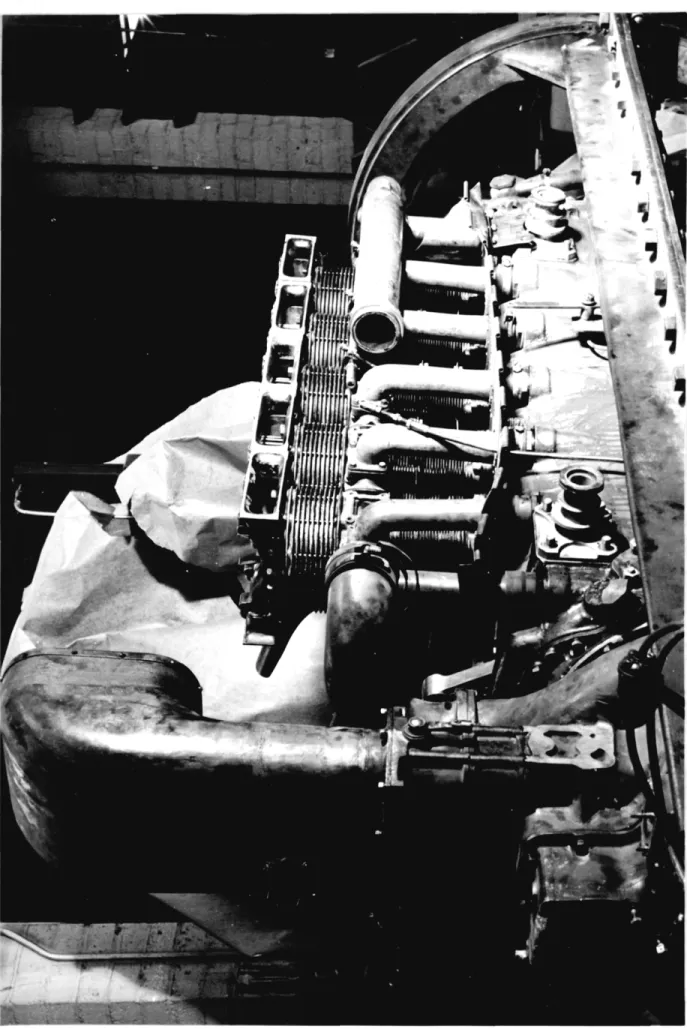
with the results obtained from the investigations. The engine is laid out in a vertioally opposed, twelve cylinder arrangement, six cylinders in a bank. Cooling is by means of air, ducted around the cylinders by means of a series of sheet metal baffles. Operation is on the four stroke cycle, with provision for forced
scavenging of the cylinders with a large amount of air. It is this provision for forced scavenging which is the
most interesting feature of the design. Induction, scavenging, and exhaust are controlled by single sleeve valves, much of the same pattern as has been used by the Bristol Aircraft Company for their series of air cooled radial engines. Fuel distribution is by means of a
mani-fold injection system, incorporating an injection pump
showing the engine prior to any dissassembly, indicates
the general layout of the engine and
accessories.
Since the unusual features of this engine are
contained in the power and induction systems this paper
will concern itself primarily with these components,
detailing other portions of the engine only as they
affect these components.The Cylinder:
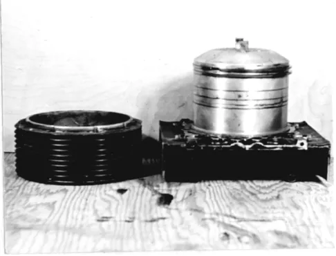
The cylinder is of conventional design for the
use of single sleeve valves. The head, of cast
alumi-num, has a long barrel with two rings, extending below the top of the sleeve, the rings effecting a seal for the gases of combustion. A separate cast aluminum spa-cer is provided to position the head properly in the
sleeve and to provide additional cooling area. The cylinder head and spacer are shown in figure 2.
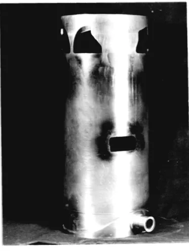
The cylinder barrel, (figure 3), is of cast bronze
construction, the bronze providing a material with a
good coefficient of heat transfer and sufficient strength to prevent pulling out of the cylinder head studs under
the imposed loads. Ports for inlet, scavenging, and
ex-haust are cast integral with the barrel. Those sections of the barrel in which it was impossible to cast fins due to the proximity of ports are provided with aluminum finned sections screwed to the main casting.
The Valve Mechanism:
sur-and exhaust, four ports being arranged at the top of the sleeve and one near the bottom to control the lower exhaust valve. Figure 4 shows the sleeve.
The sleeve valve is driven by means of a counter-shaft carrying bevel gears which mesh with gears on short shafts which extend through the crankcase wall and carry on their ends the eccentric and ball and socket joint which actuates the valve. The countershaft is shown in figure 5.
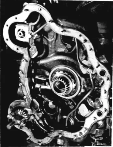
The countershaft is driven off the crankshaft by a train of spur gears which drives a planetary reduction gear system at crankshaft speed. This planetary system in turn drives the countershaft at half crankshaft speed and provides, by means of a worm gear, a method of chang-ing the valve timchang-ing while the engine is in operation. Individual timing of separate sleeves is accomplished by rotating the bevel gears on the countershaft, these be-ing secured by keys which may be placed in any one of a number of keyways, thus giving precise adjustment. This
individual adjustment necessitates the removal of the
timing gear case. The crankshaft drive gear and the planetary system for the lower countershaft is shown in figure 6. Figure 7 shows the spur gear train which is operated by the crankshaft gear. This photograph, taken
from the front of the timing gear case, shows in the upper left hand corner the planetary system for the countershaft, clearly illustrating the method of splin ing this to the countershaft. In the lower right hand corner is shown the stationary gear of the planetary system and the worm for its adjustment. The operating handle and locking plate for this control on the upper bank may be seen in the top center of the photograph.
The Piston and Connecting Rod:
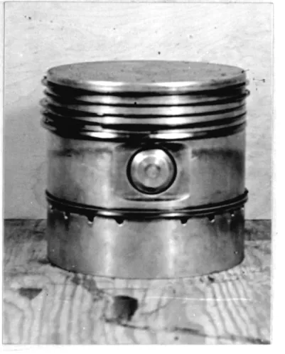
The piston is of cast aluminum construction of conventional design, the top being perfectly flat. Seven
rings are provided, four compression rings and one wiper
ring at the top of the piston
and two oil rings just
above the skirt. Holes are drilled through the piston
wall at this point to control lubrioation.
The wrist pin, of machined steel construction
with aluminum end caps, is 6f free floating design, the aluminum caps preventing the pin from scoring the sleeve. The piston and wrist pin assembly is illustrated in figm" ure 8.
The connecting rod assembly is of conventional fork and blade design. Construction is of steel with bronze bearing inserts. A high degree of finish has been achieved in the manufacture of this assembly.
Fig-ure 9 illustrates the connecting rod assembly. At the bottom of this photograph is also shown the eccentric
The crankshaft is of the design normally used in six cylinder engines with throws at 120 degrees. Due to the inadvisability of completely dismantling the engine no further investigation was made of the crankshaft and
its components.
Supercharger and Induction System:
The supercharger and drive mechanism form part of
the accessory drive case which is directly attached to the rear of the crankcase. The supercharger is driven
off the crankshaft by means of a spur gear train at 8.5
times engine speed. The drive shaft runs concentrically
with the impeller, the impeller shaft being supported on
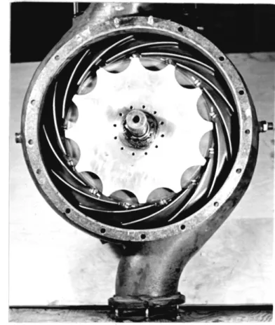
bearings on the drive shaft. Figure 10, showing the front of the blower case, illustrates the impeller and
diffuser, together with the splined end of the drive
shaft which engages with the crankshaft. The rear view of the casting,(figure 11), shows the supercharger
gear-ing and, in the lower part of the castgear-ing, the drive for the magnetos (the magnetos were removed during disassem-bly prior to this photograph). The fittings on the side of the blower casting, which are apparentlin the photo-graph, are evidently intended to bleed off air at super-charger pressure to control the fuel pump and to actuate cockpit instruments.
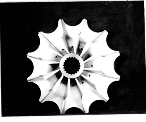
The. impeller itself, (figure 12), is of aluminum
construction of a high degree of worksmanship and
fin-ish,
The design is of the usual pattern for
centrifu-gal compressors, the row of holes shown in the
illustra-tion being provided to equalize the pressure on front
and rear of the impeller and prevent excessive thrust
on the bearings.
Lubrication for the impeller shaft is
provided from the crankshaft lubrication system, the end
of the impeller shaft being fitted with seal rings to
prevent oil leakage.
These rings may be seen in figure
10.
The diffuser is of machined steel, fastened
to,
the blower casing by means of screws.
As with the other
parts of the supercharger the diffuser shows a high
de-gree of finish.
Figure 15 shows the front of the rear casing of
the engine, illustrating the drives for various
accessor-ies such as lubricating oil pumps, many of which were not
mounted when the engine was delivered.
The rear of this
casing carries the mountings for the accessories such as
the fuel pump and had been damaged before the engine was
received at the laboratory.
Induction of the air to the cylinders is by means of parallel manifolds running alongside each bank of cylinders, which are connected to the scavenging ports of the cylinders by short connectors set at right angles to the main manifold. These connectors contain small
Junction with the main throttle on the supercharger in-let, the exact connection being uncertain due to the
damaged condition of the engine. The main manifolds are connected together at the forward end of the cylinder bank and thence are connected to the injection manifold.
The injection manifolding system will be detailed in the section dealing with the fuel pump. The induction system
may be clearly seen .in figures l(a) and l(b).
The Injection System:
The
injection system consists of a twelve
cylin-der injection pump, the pump control mechanism, the
in-jection nozzles, and two manifolds, one for each bank of
oylinders, into which the
nozzles discharge.
The injection pump is of cylindrical pattern, the
design largely following that of Friedrich Deckel, A. G.,
of Munich.
The pump is driven at half engine speed, the
individual pistons being actuated by means of a wobble
plate. Control of the amount of the fuel delivered per
,stroke is
accomplished
in the same manner as in the Deckel
pump by means of a rack which controls the cutoff point,
thereby limiting the effective length of the stroke.
The pump control mechanism, which determines the
fuel delivery of the pump under operating conditions, is
actuated by
air at manifold pressure.
The power to move
the pump rack is supplied by
oil
pressure, the
oil
possi-10
bly being supplied from the lubricating oil pump of the
engine.
A diagram of this oil system,(figure 14),is
in-cluded in the appendix.
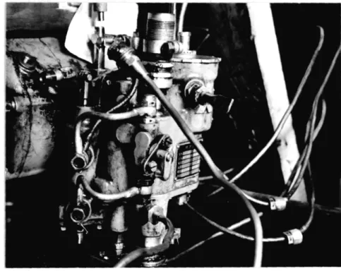
Figure 15 shows the control
as-sembled to the pump.
The control mechanism disassembled from the pump
is shown.in figure 16.
The bellows case appears in the
upper right hand corner of the assembly and the linkage-between the pilot valve and the pump rack may be seen in the top center of the photograph, .This linkage is prin-cipally to control the travel of the main actuating pia-ton, which is connected to the lower part of the pump rack. The main actuating piston and piston rod may be
clearly seen in the left center of figure 17 which illue-trates the control partially disassembled. The method of attaching this piston to the pump rack is uncertain
as this part of the mechanism was missing when the unit
was received. The actuating piston appears also in the
photograph of the lower section of the control
mechan-ism housing (figure 18).
The upper half of the control housing, a bottom
view of which is shown in figure 19, contains the pilot
valve and its actuating system. This system consists of
a brass bellows and a piston connected to the pilot valve through a lever system. This lever system appears in the right half of the illustration, the upper and longer
to the piston. -The arrangement is such that, from all
indications, the bellows merely compensates for the
tem-perature of the air bled from the manifold, the main actuation of the pilot valve being accomplished by air
pressure impinging on the piston.
The control mechanism is also fitted with an emer-gency control device to prevent fuel from being entirely
out off should the actuating oil pressure fail. This
consists of a spring loaded piston actuating a stop lever.
Under normal operating conditions oil pressure acting on
the piston forces the stop out of contact with the pilot
valve - pump rack linkage. Upon release of the oil
pres-sure the spring forces the stop into contact with the linkage and prevents the rack from being moved into a position of fuel cutoff. This device may be seen on the
left side of the control mechanism in figure 15. Since the oil pressure was shut off when the photograph was made, the stop is in the up, or emergency operation,
position.
A series of tests was run on the injection pump and control mechanism with a view towards determining the manifold pressures used by the engine. Air pressure and oil pressure to actuate the controls were supplied from outside sources, the pump being driven by an eleo-trio motor. This test set-up is illustrated in figure 20. Since the pump control is actuated by manifold
deter-mined by noting the pressure which produced maximum fuel
delivery and a curve of fuel delivery versus manifold
pressure could be constructed. Using these figures and
assumed fuel-air
ratios,
the operating conditions of the
engine could be more accurately estimated.
Due to the damaged condition in which the engine
was received it was impossible to obtain results from
this series of tests. The linkage which moved the pump
rack was missing and some damage had been done to the
con-trol mechanism, with the result that it would not give
consistent control. Attempts to rig a substitute
oper-ating linkage failed and it was deemed
impractical
to
continue this line of investigation further.
However, some runs were made with the control
mech-anism removed and a
micrometer used to position the pump
rack. From these runs a curve of pump delivery versus
rack setting was
obtained, which is shown in figure 21.
Assuming the engine operated at 2400 ipm., the maximum
pump delivery, using the figures for air consumption
ob-tained from the
supercharger calculations, gives a
fuel-air ratio of .146. This reasonable figure serves to
veri-fy the results obtained for the supercharger performance.Fuel from the injection pump is delivered through high pressure lines to the injection nozzles which are positioned in a common inlet manifold for each bank of
cylinders. Air is introduced into this manifold at the forward end, directly from the scavenging manifold. A
throttle valve is placed in the manifold at this point so that the pressure and amount of air delivered may be controlled. This was obviously introduced in the design for experimental purposes. This manifolding system may be seen on the assembled engine in figure 1(a) and
dis-assembled in figure 1(c).
Since the injection manifolds are located on the opposite side of the engine from the cylinder inlet ports, the inlet pipes run from the manifolds through the
crank-case and thence upwards to their connection with the inlet ports. These pipes form an intergral part of the
crank-case, with the exception of the upper portion, running
from the base of the cylinder barrel to the inlet ports,
which is a separate section of tubing. Seven inlet pipes
are provided, five of which are divided at .their upper
extremities to connect with two adjacent cylinders, and
two, those located at the front and rear of the cylinder
bank, which serve only one cylinder.
Six injection
nozzles of standard pattern are
pro-vided in each injection manifold. These are located
di-rectly opposite the manifold openings of the first six
inlet pipes. Provision had been made for the location
of an additional nozzle to serve the last inlet pipe in
the bank. Evidently this additional nozzle opening was
provided to allow the placement of the six nozzles
oppo-site the forward six inlet pipes or the after six,
14
Discussion of Results
From the foregoing description the experimental
nature of this design is immediately apparent.
Basic-ally, the design of the engine appears to have been
care-fully considered but little attention has been paid to
the requirements
of maintenance.
Certain rassemblies,
such as the lubricating oil pump, which require frequent
removal for service or replacement, have been located
with little regard for such operations. Such details
would have to be considerably modified prior to large scale production if the design were to 6ompare favorably with current domestic products.
This design contains two features which are of major interest; the high degree of forced scavenging
used on a four stroke cycle and the unusual method of
fuel injection. The former will be discussed with a view towards determining the reason for the use of such a system and whether the additional power and
complioa-tion required thereby was justified. The latter will
be considered in such a way so as to determine its
effectiveness over that of more conventional systems of fuel distribution.
Several reasons have become apparent for the
ap-plication of such a method of forced scavenging to a four stroke engine. The primary result of the application of such a system would be to completely remove residual gases
from the cylinder. This would result in an increase in volumetrio efficiency and a consequent raising of the maximum power which could be obtained from a given
throt-tie setting. A secondary result of such scavenging would be to cool the cylinder walls, thus preventing the
for-mation of localized hot spots. This would remove one of
the causes of detonation and permit the use of lower
fuel-air ratios and fuels of poorer anti-detonant properties
than are normally required by aircraft engines of this capacity.
To hohieve the maximum benefit of the forced sea-venging as regards the removal of residual gas the place-ment and timing of the valves must be such as to insure
a free and unobstructed flow of exhaust gases and scaveng-ing air durscaveng-ing the initial period of scavengscaveng-ing. In this design a free flow of gases has been achieved by placing an exhaust port immediately above the position occupied by the piston at the bottom of the stroke. This results
in a sensibly uniflow movement of the exhaust gases
dur-ing the blowdown period. Reference to the valve timdur-ing
diagram, (figure 22), will reveal that this port is opened
considerably in advance of the exhaust ports placed in
the more conventional position at the top of the cylinder,
thus permitting the uniflow movement of the gases to con-tinue undisturbed during the period of high cylinder
pres-sure.
16
must next be cleansed of those residual gases which did
not escape in the initial period. In this design such has been accomplished by next opening the upper exhaust ports, followed shortly by the opening of the intake side
scavenging port. This results in a flow of scavenging air across the upper part of the cylinder, removing the residual gas which is normally entrapped in the compres-sion space. It will be noted that the bottom exhaust port remains open for a time after the scavenging port
is opened, thus permitting the scavenging air to
acceler-ate the removal of gases from the lower half df the
cylin-der. Piston movement during this period is relatively small, hence the major part of the removal of exhaust gases is accomplished in this interval by the blowdown process and the scavenging air rather than by movement
of the piston.
As the piston moves upward on the exhaust stroke the top ring closes the bottom exhaust port, the upper exhaust ports remaining open. This creates a flow of scavenging air directly across the top of the cylinder,
removing the exhaust gases forced up ahead of the moving
piston. When the piston has completed approximately half the stroke the exhaust side scavenging port is opened, in-troducing an additional flow of scavenging air and creat-ing a turbulence which tends to sweep the remaincreat-ing resid-ual gas from any dead spaces on the oposite, or inlet,
In view of the large scavenging air flow
exist-ing when both inlet and exhaust side scavengexist-ing and
up-per exhaust ports are open it would be inadvisable to
open the intake ports until relatively late in the cycle
due to the excessive losses of fresh charge which would
occur.
It will be seen from the valve timing diagram
that such a late opening has been incorporated in this
design.
During the downward movement of the piston on the
inlet stroke the scavenging ports remain open, thus the
cylinder is being supplied with both pure air and
fuel-air mixture.
The location of the ports is such that in
all probability sufficient turbulence exists in the
cylin-der to give good mixing of the fuel-air mixture with the
scavenging air.
Since the major part of the air is
sup-plied by the scavenging system
it is reasonable to assume
that a very rich mixture is supplied to the inlet ports
in order to maintain a combustible mixture in the oylinop
der.
As may be seen in the valve timing diagram the
soa-venging ports close completely at approximately the same
time.
This leaves 31 degrees during which the inlet
ports deliver mixture with no additional air from the
scavenging ports.
As has been noted previously this
mix-ture supplied by the inlet ports is necessarily very rich.
This gives rise to the probability that some
stratifioa-tion of the charge in the cylinder is obtained.
Such
stratification would be desirable since a richer, and
18
more easily ignited, mixture would exist at the top of the combustion chamber near the spark, permitting the-use of a leaner overall fuel-air ratio. Greater economy of operation would therefore result.
From the foregoing discussion it may been seen that the secondary result of the application of such a forced scavenging system, namely the cooling of the cylin-der walls, has been achieved by the use of such a large amount of scavenging. As has been noted previously this
would eliminate one of the causes of detonation, thus
permitting the use of lower fuel-air ratios and poorer grade fuel, again resulting in better economy of
opera-tion.
The provision for the delivery of such a large
amount of air to the engine for scavenging purposes
necee-sitates a supercharger of greater size than that which
would be required by the same engine without the
scaven-ging feature. Applying empirical formulae, (see the cal-culations in Appendix IV and the plot of Supercharger Pressure Ratio vs. Engine Speed, figure 23), to the data
obtained from the supercharger it has been found that a blower of more than twice the capacity required without
scavenging is used in this design. Thus, at an engine speed of 2400 rpm., it was calculated that the superchar-ger delivers 275 pounds of air per minute at a pressure ratio of 1.89. At this speed, assuming a volumetric
air per minute, leaving
166.9 pounds
of air per minute
to be used for scavenging purposes.
Converting the
above into horsepower, the blower uses a total of 289 HP,,
114 HP. of which is required to supply air to the engine
and 175 HP. to provide the additional air for scavenging.
The second unusual feature of this engine design
is the
fuel
injection
and
the inlet
manifold
system.
As
was noted previously the
injection
pump and nozzles are
of conventional design and thus warrant no
consideration
here.
However, the inlet manifold system is of unique
design and it is this feature which will next be discussed.
As was mentioned before, each inlet pipe supplies
two cylinders,
with the exception of the two pipes at
the ends of the
bank, which supply only one apiece. Each
of these pipes, excepting the rearmost pipe on the bank,
has a nozzle located directly in line with its opening
into the injection manifold. Thus, since the individual
injection nozzles are timed to the inlet period of only
one cylinder, only that cylinder to which it is timed
will receive fuel directly from a nozzle. The adjacent
cylinder, sefved by the same inlet pipe, will receive
through that inlet pipe during its inlet period the
mix-tre existing in the common injection manifold at that
time, a mixture necessarily much leaner than that supplied directly by a nozzle. This cylinder, however, receives directly from the adjacent nozzle, this system being
20
In light of the short period during which the inlet ports are open it will be seen that a relatively large port area is required. The achievement of this port area, keeping the dimensions of the individual ports within
rea-sonable limits, necessitates the provision of two inlet ports. Possibly the manifolding system used was the best
design available to fulfill these conditions without over-complication.
Conclusions
The investigators have drawn several conclusions
regarding the efficacy and justification of the unusual
features of this engine design.
From considerations of power alone, it has been
found, utilizing the figures for required supercharger
power and an estimate of the performance of the engine,
(see
calculations, Appendix IV), that an increase in
vol-umetrio efficiency of the engine of approximately 14% is
required to justify the use of such scavenging, As noted,
these figures are based on the assumption that the
addi-tion of scavenging increases the volumetric efficiency
to 100%.
However, considering the large amount of
sca-venging used, it is entirely possible that the volumetric
efficiency may be increased to near the theoretical
maxi-mum of 1181,(r/r-l), by the removal of residual gas from
the compression space.
Based on these figures the
theo-retical increase required to justify the scavenging is
calculated to be 13%, while the actual increase over
oper-ation without scavenging will greatly exceed this figure,
possibly being as high as a 28% increase, (see calculations,
Appendix IV).
Throughout this discussion negligible
pres-sure losses
across
the valves have been assumed, a
reason-able assumption since intake-
is through four large ports
and high flow coefficients are normally obtained with the
use of sleeve valves. However, to this consideration of
power requirements the benefits derived from the cooling
22
effects of the scavenging must be added. Taking into account the large amount of scavenging used,the
inves-tigators have concluded that such a system is justified, giving at least the required increase of volumetric effi-ciency in addition to increasing the internal cooling by
an appreciable amount.
The principal fault of the manifolding would seem to be the provision for one of the cylinder inlet pipes taking mixture from the manifold, rather than the mixture supplied by the nozzle. Due to the length of the manifold and the location of the nozzles it may be assumed that the fuel-air ratio existing in the manifold will vary consid-erably, This will introduce an appreciable variation in the fuel-air ratio received by the various cylinders. Therefore it is difficult to justify the use of such a manifold design and in alprobability a system of individ-ual inlet manifolds, such as that used in the R. A. E.
-Hobson injection system, would give more satisfactory
Suggestions for Future Investigation
In the opinion of the investigators the results
of this paper have shown the need for further research on the forced scavenging system. This research would best take the form of an actual operation of such a
sca-venging system, utilizing a single cylinder removed from the engine mounted on a suitably constructed crankcase. In this manner verification of the analysis contained in
this paper could be made and quantitative data obtained for a wide range of operating conditions.
A metallurgical analysis might also be made on the operating parts of the engine, special attention being paid to the composition, mechanical properties, and heat
transfer coefficients of the bronze used for the cylinder barrels.
APPENDIX I Engine Data
injection, four stroke, forced scavenging, sleeve valve.
No. of Cylinders: 12, in two banks of 6 each. Bore: 5.12 inches (130 mm.).
Stroke:
5.51 inches, (140 mm.).
Displacement: 1365 cubic inches (22.4 liters).
Compression Ratio:
6.5: 1
Propeller Reduction Gear Ratio: 1'95: 1 Estimated BHP: 1000 at 2400 rpm.
Direction of Rotation: Crankshaft - Counterclookwise. (from anti-prop. end) Prop. Shaft - Clockwise.
Valve Gear: Crank operated sleeves actuated through bevel gears on counter shaft. Valve timing can be
adjusted individually or as a unit controlling
all six valves on a bank. (Two inlet ports, two scavenging ports, and three exhaust ports per cylinder)
Firing Order: 1-9-5-12-5-8-6-10-2-?&-4-11 After 7-8-9-10-11-12 Forward End 6-5-4- 3- 2- 1 End
Overall Dimensions: Length: 72 inches (not including fuel pump or prop shaft).
Height: 47 inches. Width: 22 inches.
Valve Timing:
Open
Close
Intakes... 80 ATO 620 ABC
Bottom Exhaust... 640 BBC 670 ABC
(by top rin
Top Exhaust... 20o BBC 550 ATO
Intake Side Scavenging... 170 ABC 100 BBC (completely
at 12o AB)
Exhaust Side Scavenging.. 750 BTO 310 ABC' Supercharger Gear Ratio: 8.5:1
Superoharger Data:
Type: Single stage, centrifugal, direct geared, aluminum
alloy impeller.
No. of Impeller Blades: 12 No. of Diffuser Blades: 13
Impeller Blade Entrance Angle: 600
Dimensions: Overall impeller diameter - 10 3/16 inches Discharge Opening: 3 7/8 inches
Intake Opening: 6 1/4 inches with 2 1/2 inch
Material Analysis
Crankcase: Aluminum Alloy. Cylinder Barrels: Cast Bronze.
Cylinder Spacer: Aluminum Alloy.
Cylinder Head: Aluminum Alloy, ( with two steel compression rings).
Pistons: Aluminum Alloy.
Conmuation .of suercharer .reassue ratios
The plot of supercharger pressure ratio (fig. 21) was
obtained using the following formula from "Superchargers
for Aircraft Engines", R.. Standerwick and W. J. King.
S )3 534
P2/P
I= q'-'6083 TI
3
V= tip speed of impeller
Tl=Inlet temperature to
supercharger
AssumhAng:
' = 75
T
1= 520o1
Calculation of suDercharmer air delivers: Engine speed= 2400 rop.m.
Supercharger speed= 20,400 r.p.m.(Assumed designed speed sea level conditions)
Qvo,
e = 30
0V
i= 2frK = 2 x 20,400 x Tr x
Vi=
33,800 Ft,/ain
Va= Vitan 300 = 33,800 x.577
=19,500Ma=Va
i fx
-144
Af o.184
Ft2
f
=.s0765#/Ft
.YP
1 = (1.89)6 T1 Y(T
2T)actual
T2=
659oR 520 x .20 5 = 139FO'fIs
Power
-=
NJ C
(T2 q Tj)/
Power c=
275
x778
$
#2
0(339)/33,000 x .75
1 Power = 9 WAir Reauirements of enaine Engine speed =2400 rop.m.
Assuming volumetric efficiency = 100%
a
-x 2 xJ
Ma 728X x .114 = 108.1 lbs/min.
1= 108.1
lbs/min.
Power. reauired for scaven nint
Power
=
Ps.c. x Ma total
Power 289 x 275
5
i08,128
x
276
275Power = 175
l
P.
for acavenging
Power = 114 HP. to suply air -for. enilne
Estimated power.
of engine
Power = Ma x F/A x EC x
y
XJ
,
=.Jo
y,
Power
=108Ul .08 x 18,900 x .318 x 778/33,000
Power
=1230 HP.
Increase of volumetric efficiency to .iusify cavenging
1230-175
1230
3230 e2 eI = .86e2-e
I=
M
epossible
=r-
=6.5
epossible
=118%
Maximum fuel-air ratio at 2400 re.Dp.m
Ma
=
108,1 lba/min.
Mf
=
15.9
bs/min. (from graph)
F/A
=.146
I r; tf~~t ~trt i -tt tr L1::e ,,
iirir:r~
c,-- ... rt, t r+c,~)L-tri~-CF:::t:'li
-LIZ
T .. :EiL
H4+-f i 44+-"T6 601a I I , I I i fL. ;;'-t , ITT : if:: : t : : t : :: ,:If Fi.I i. irl+ +, n
L.,;.:i
tl
'-+,
=:':f.: " ! -I I I I. . . - . 11 444. 1 11 7 1 i it -t - :i+ r t -- tt e HH-j i -Ci~~l~~~i L~CLeci (-(Ht-t -;-l; 4w)-- eu ( -H~~e-j::: -iti kk~c;C~cCJCt--, -Cc -. C---tz ttI CrC_ "I~fiff~ii~-~fffFRff;i+f~'i ~Fffitff~ifff ri t -1- ~~+ t++rrr-tttz.. :~.
- --m++-H-iiiitiia'
-t I -III T I t ItO r
to
Valve Timing
Diagram*
u3-Valv TiigDarm
I I I ~ I I I I I I1II I I I
r(
""c~
....
"'"~
i
.. ..
i
r:
_2;; - ~ .ii ll ii ; r•.
4
, H Iiiif - ~ ii •-f t. : -H 1 -1 4+t 4-"' f ¢4 ti -t I f '''° +; + + 4: - . -4- ++, .... ~S "I, +t~S- f :t . .. . . 4-.. . . . . . • . - 4 ,-, -q- q:,i. .. t .-. ... .,. , ,.** .. .... i.. t f ' : I. T... -4 4 I T I T f I T 1 1 T tt I T 1 1 1 1 1 T I + +, 4 T IT, T F 7+-4 T . ... .. !.f iii ;iE -H H I' .. t ~ l4i . .. -+41 + Z4 r i i i +t f-44 4 I 1 - It - 4 'i 1 + ,- li:-ft * : .... ..~, ,~,, r i,4-C* .- 1 JI I + n +4-clti -I 1. re*c~. t ,,. ~ ~ ff~~::: ;4 ti~r~~ ~ tt f::ifii~fl 1 .... ~. ~..~. -4-'-,:I::~t::;I::: :;:1::: 1::, :::~::; il~ j 4 1 1 1 ~() ~ ) . I t tt 4-4t 4.,. 1 44-4 1 444 .4 -*4 Fig. 23.i-d:C-'
Vi. ( haaet *d4e view or engine.
0 M
p' I e ** 1 1 fi
.j
t
I
4i.
I
... ... '' '~ ''
. . .. .. .. . . . . . . .
1 .1 .. ... .. ..
Fig. 1 (a): Exhaust side view of engine.
f
S~ d ~J1
II _ c
vX
4 j
1 vj
P
Fig. 1 (c): Manifold cover removed (inlet pipes).
Fig. 4: Sleeve
Fig. 8: Piston.
Fig. 9: Connecting rod.
Jk
*
AmFig. 12: Impeller J7
tli
r tr. p
Ij'
IuOil Frowen S
po-osw¢ Soup-cc
FUEL PUMP CONTROL
ACTUATING OIL SYSTEM
Fi.
14.
SeIte dv
Switck
Valve-Fuv.t fA-t
A)5+% Ii%, Pistow
Fig. 15: Fuel pump control.
Fig, 19: Upper half, fuel pump control.
Bibliography
Taylor and Taylor: "The Internal Combustion Engine"
International Textbook
Co.,
1942.
R. G. Standerwick and W. J. King:
"Superohargers for
Aircraft Engines"
Supercharger Engineering Division, General Electric Co., West Lynn, Mass. Friedrich Deckel, A. G., Munich, Germany: Drawings of
Deokel fuel pump. Drawings courtesy of U.S.A.A.F. Air Technical Command Wright Field, Dayton, Ohio.