Development and Evaluation of Biarticular Transtibial
Prostheses for Level-Ground Amputee Walking
by
Michael Frederick Eilenberg
B.S. Computer & Systems EngineeringB.S. Mechanical Engineering Rensselaer Polytechnic Institute (2006)
S.M. Mechanical Engineering
Massachusetts Institute of Technology (2009)
MASSACHUSETTS INSTITUTE OF TECHNOLOGY
FEB 1
52017
LIBRARIES
ARCHNES
Submitted to the Department of Mechanical Engineering in partial fulfillment of the requirements for the degree of
Doctor of Philosophy at the
MASSACHUSETTS INSTITUTE OF TECHNOLOGY
February 2017
C Massachusetts Institute of Technology 2017. All rights reserved
Author ....
Signature redacted
/' flpn~ivtmpnt. ofMpeh~inie~1 En~rinppvin~
Certified by ...
Signature redacted
November 18, 2016
Hugh M. Herr Associate Professor of Media Arts and Sciences Associate Professor of Health Sciences and Technology Thesis Supervisor C ertified by ...
Accepted by ...
..
Signature redacted
David L. Trumper Professor of Mechanical Engineering Thesis Committee Chair
Signature redacted
Rohan Abeyaratne
...
Den rtment of Mechanic I En ineerin
Development and Evaluation of Biarticular Transtibial Prostheses for Level-Ground Amputee Walking
by
Michael Frederick Eilenberg
Submitted to the Department of Mechanical Engineering on November 18, 2016, in partial fulfillment of the
requirements for the degree of Doctor of Philosophy
Abstract
In the last several years, great strides have been made toward the development of transtibial prostheses that match the functionality of their corresponding biological structures. However, these devices are fundamentally limited because they only emulate the biological ankle-foot complex. In contrast, the gastrocnemius calf muscle spans both the ankle and knee joint, and thus provides biarticular function. Therefore, it may be prudent for transtibial prostheses to include actuation at both the ankle and knee joints of an affected limb.
This thesis presents the development of two such biarticular prosthesis systems. The first, tested on two participants, employed a quasi-passive clutched-spring knee orthosis, approximating the largely isometric behavior of the biological gastrocnemius. The second device, tested on six participants, provided positive net mechanical work with a tethered knee orthosis, controlled using a neuromuscular model. Both devices utilized a commercial powered ankle-foot prosthesis. Participants with unilateral transtibial amputation walked with these biarticular prostheses in two separate studies on an instrumented treadmill while motion, force, electromyographic, and metabolic data were collected. Data were analyzed to determine differences resulting from the activation of each knee orthosis, compared to the orthosis behaving as a free-joint. We hypothesized that the active conditions would reduce joint kinetic demands, and consequently metabolic cost, compared to the control conditions.
The quasi-passive system was capable of reducing both affected-side knee and hip moment impulse and positive mechanical work in both participants during the late stance knee flexion phase of walking, compared to the control condition. The metabolic cost of walking was also reduced for both participants. The powered artificial gastrocnemius reduced affected-side biological knee flexion moment impulse by 0.022 +/- 0.018 Nm/kg (p = 0.03), and affected-side hip positive work by 0.074 +/- 0.025 J/kg (p = 0.004) during late stance knee flexion, compared to the control condition. However, the data did not support our hypothesis that metabolism would decrease, as two of the participants did not display a metabolic reduction. These results highlight the kinetic benefits of an artificial gastrocnemius for transtibial amputee gait. However, further study is warranted to determine the requirements for achieving a consistent metabolic improvement.
Thesis Supervisor: Hugh Herr
Title: Associate Professor of Media Arts and Sciences
Acknowledgments
There are so many to whom I'd like to thank that I feel like I am giving an Oscar speech. First, I would like to thank my advisor, Professor Hugh Herr, for supporting me throughout my entire graduate career while providing an environment where I could so freely explore, experiment, and learn. Most importantly, thank you for convincing me to pursue the PhD in the first place. I look forward to doing "creative work for the rest of [my] life", thanks to your very persuasive argument for me to stay on after my master's work.
To my committee, Professor David Trumper and Professor Sangbae Kim, your words of wisdom, encouragement, and gentle pushes in the right direction over the past several years have helped get me to this day. Thank you for your patience and understanding, especially when my research updates were less-than-perfectly clear.
I thank NASA, for funding the larger project of which I became a part these last few
years. Without your funding, the entire tethered system would not have existed.
A hearty thank you to my good friends and colleagues here in Biomech over the
years. You've made the lab more of a family than a workplace, and I've learned more from you than you know: Madalyn Berns, Bruce Deffenbaugh, Grant Elliott, Todd Farrell, Matt Furtney David Hill, Bevin Lin, Luke Mooney, Arthur Petron, David Sengeh, and Jing Wang. Special thanks to Jiun-Yih Kuan for letting me on the bandwagon with the simulator project and being so gracious in showing me the ropes (or should I say cables). Ken Pasch, thank you for your insight with this simulator project; you always had just the right questions to ask. Jared Markowitz, thank you for taking so much of your post-graduation time to guide me through your very complex modeling and optimization code. Ken Endo, your groundbreaking work with the first artificial gastrocnemius enabled me to get a running start. Jean-Franqois Duval, your strain gauge amplifiers were, quite literally, instrumental. Cameron Taylor, your inexplicably enthusiastic support with clinical trials very likely saved my over-tired mind from forgetting to hit record on multiple occasions. Pavitra Krishnaswamy, Elliott Rouse, and Olli Kannape, you helped steady me during crises, and I am so grateful to have your support. Ernesto Martinez-Villalpando and Sam Au, you were two of the first people I met at the lab, and I've
cherished both your friendship and mentorship over all these years.
To all of my study participants (you know who you are), I literally could not have done this without you. Thank you for bearing with me, through the forms, travel, boring down-time, hardware failures, grueling long sessions, and repeat visits. You
are so admirable and truly inspiring, and it has been my honor to work with you. To the Biomech admins throughout the ages, especially Tesha Myers, Sarah (Hunter) Ralston, and Lindsey Reynolds- you made me feel at home from the start, and I always felt I had a sympathetic ear in your presence.
Thank you to everyone who has worked as a UROP with me: Deema, Priya, Raul, Rachel, Laura, Dabin, and Arden. I appreciate your eagerness to help in whatever was needed.
To my friends and family everywhere (and double-counting some of Biomech here), you've helped me maintain a life outside of work, and part of the reason I'm so happy is because I have all of you in my life.
Ozzie, I know you can't read this, but I'll give you a bunch of treats after turning this in as a thank you for the countless hours you spent keeping me company while
I put this dissertation together.
Finally, to my family: Steven, Hel6na, Sammi, and Jenna, I never felt I could fall very far with all of you there to catch me. Thank you for always being there with your boundless love.
Contents
Chapter 1...
15
1.1 Specific aim s...15 1.2 H ypotheses ... 15 1.3 Thesis contributions... 16Chapter 2 ...
17
2.1 M otivation ... 17 2.2 Sign conventions ... 202.3 Norm al ankle and knee biological function ... 21
Chapter 3...
23
3.1 Introduction...23
3.2 M ethods ... 24
3 .2 .1 H a rd w a re ... 2 4 3.2.1.1 Powered Ankle-Foot Prosthesis ... 24
3.2.1.2 Clutch-Spring Joint... 26
3.2.2 M odeling and Spring Stiffness Selection ... 27
3.2.2.1 Target Biological Behavior ... 27
3.2.2.2 Target M usculoskeletal M odel... 28
3.2.2.3 Optim ization ... 30
3 .2 .3 C o n tro l ... 3 1 3.2.3.1 Control Electronics...31
3.2.3.1 Control Algorithm ... 32
3.2.4 Experim ental Protocol... 36
3.2.5 Data Processing ... 37
3.3 Results ... 39
3.3.1 M odeling...39
3.3.2 Ankle Prosthesis Net W ork ... 39
3.3.3 Affected Knee Kinem atics ... 40
3.3.4 Affected Knee Kinetics ... 41
3.3.5 Affected Hip Kinetics... 43
3.3.6 Affected Knee Electromyography... 45
3.3.7 M etabolism ... 47
C hapter 4...
51
4.1 Overview ... 51
4 .1.1 M otiv a tion ... 5 1 4.2 M ethods ... 52
4.2.1 M otor Drive M odule ... 52
4.2.2 Cable Drive ... 53
4.2.2.1 Cable Selection...55
4.2.2.2 Cable Tensioner ... 55
4.2.3 Joint M echanism ... 55
4.2.4 Custom Knee Brace ... 57
4.2.5 n ... 58
4.2.6 Safety Features...59
4 .2 .7 S e n so rs ... 6 0 4.2.7.1 Sensor Calibration ... 61
4.2.8 Open-Loop System Characterization...61
4.2.9 Joint Torque Control ... 63
4.2.10 Stance Phase Torque Control...64
4.2.11 Swing Phase Torque Control... 64
4.2.11.1 Software Lim its... 65
4.2.11.2 Closed-Loop System Characterization ... 66
4.2.12 M etabolic Validation ... 66
4.3 Results ... 68
4.3.1 M echatronic Design Specifications ... 68
4.3.2 Friction Characterization...69
4.3.3 Torque-Control Response Characteristics ... 69
4.3.4 M etabolic Validation ... 71
4.3.5 Torque Errors During W alking... 73
4.4 Discussion... 73
C hapter 5...
75
5.1 Overview ... 75
5.2 M ethods ... 76
5.2.1 Non-Am putee Data Collection ... 76
5.2.2 Data Processing ... 77
5.2.3 Estim ating M uscle Activations ... 78
5.2.4.1 Hill M odel...81
5.2.4.2 M uscle-Tendon Dynamics... 83
5.2.5 M orphological Optimization...84
5.2.5.1 Param eters...84
5.2.5.2 Preferred W alking Speed...85
5.2.5.3 Optim ization Strategy ... 85
5.2.6 Spinal Reflex M odel... 91
5.2.6.1 Reflex Optimization ... 92
5.2.7 Neurom uscular Controller ... 93
5.3 Results...95
5.3.1 Non-amputee m atching... 95
5.3.2 Non-amputee Data Collection... 95
5.3.3 M orphological Parameter Optimization: ... 96
5.3.4 Reflex Optimization... 96
Chapter 6...
97
6.1 Overview ... 97
6.2 M ethods ... 97
6.2.1 Data Collection Protocol...97
6.2.2 Data Processing ... 99
6.3 Results ... 103
6.3.1 AG overall device perform ance ... 103
6.3.2 M etabolic Power ... 103 6.3.3 Kinem atics...105 6.3.4 Joint M om ents...106 6 .3 .5 P ow e rs ... 1 10 6.3.6 Electromyography ... 114 6.4 Discussion...118 6 .4 .1 K in etics ... 1 18 6.4.2 Kinem atics...118 6 .4 .3 E M G ... 1 19 6.4.4 M etabolic Results ... 119
6.4.5 Potential M echanisms for M etabolic Reduction ... 120
6.4.6 Conclusions...121
7 .2 F u tu re w ork ... 124
7.2.1 M ech atronic D esign ... 124
7.2.2 C linical Study D esign ... 125
Chapter 8...
127
8.1 Individual Joint Biomechanics ... 127
8.2 Individual Electromyography...135
Figures
Figure 1: The BiOM powered ankle-foot prosthesis. ... 18
Figure 2: Calf muscle anatomy highlighting the gastrocnemius muscle...20
Figure 3: Leg-joint sign convention in the sagittal plane ... 20
Figure 4: Knee function in the human gait cycle for normal level-ground walking..22
Figure 5: Joint mechanism of the quasi-passive artificial gastrocnemius...25
Figure 6: Quasi-passive artificial gastrocnemius ... 26
Figure 7: The Endo-Herr leg model using quasi-passive elements...29
Figure 8: Quasi-passive leg model with monoarticular gastrocnemius spring ... 30
Figure 9: Example action of the clutch engagement...31
Figure 10: Finite state machine for the quasi-passive artificial gastrocnemius ... 33
Figure 11: Affected-side iknee kinematics with the QPAG...40
Figure 12: Affected-side knee flexion moment components with the QPAG...41
Figure 13: Affected-side knee power components with the QPAG...42
Figure 14: Affected-side hip flexion moment components with the QPAG...43
Figure 15: Affected hip power with the quasi-passive artificial gastrocnemius...44
Figure 16: Affected-side knee muscle EMG for Subject 1 with the QPAG ... 46
Figure 17: Affected-side knee muscle EMG for Subject 2 with the QPAG ... 47
Figure 18: Metabolic power changes with the QPAG ... 48
Figure 19: M otor drive unit and tensioner... 53
Figure 20: Conduit linkage for the powered artificial gastrocnemius ... 53
Figure 21: Conduit elem ent ... 54
Figure 22: Powered artificial gastroenemius joint mechanism...56
Figure 23: Sectional view of the powered artificial gastrocnemius joint...57
Figure 24: Knee brace and socket attachment... 58
Figure 25: C ustom knee braces...59
Figure 26: Custom strain gauge-based torque sensor ... 60
Figure 27: Sensor calibration mounting platform ... 61
Figure 28: Swept sine input for system identification...62
Figure 29: Torque control schem atic ... 65
Figure 30: Trapezoidal torque response ... 68
Figure 31: Open-loop system response ... 70
Figure 32: Closed-loop system response... 71
Figure 33: Metabolic power of non-amputees with the tethered knee orthosis...72
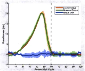
Figure 34: Representative closed-loop system response during walking trials...72
Figure 35: H ill-type m uscle m odel... 81
Figure 36: Empirically-determined muscle metabolic power...90
Figure 37: Neuromuscular controller including spinal reflex loop ... 94
Figure 38: Final cost values for the morphological parameter optimization...96
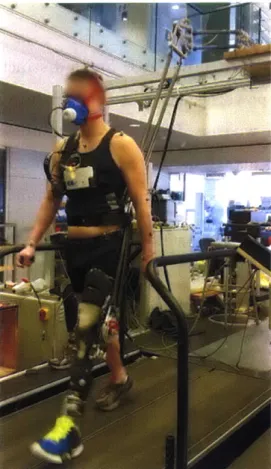
Figure 39: Experimental setup with the powered Artificial Gastrocnemius...98
Figure 40: Individual joint angles during walking for amputee participants...106
Net joint moments with the powered AG ... 108
Affected-side knee extension moment impulse in late stance flexion.... 110
Joint powers during walking with the powered AG ... 111
AG effect on affected-side hip positive power...113
Changes in joint positive work in late stance knee flexion. ... 114
EMG changes when walking with the powered AG...115
Percent change in hamstrings EMG with the powered AG...116
Average changes in quadriceps EMG with the powered AG...117
EMG changes compared to baseline activity ... 117
Figure Figure Figure Figure Figure Figure Figure Figure Figure Figure Figure Figure Figure Figure Figure Figure Figure Figure Figure Figure Figure Figure 42: 43: 44: 45: 46: 47: 48: 49: 50: 51: 52: 53: 54: 55: 56: 57: 58: 59: 60: 61: 62: 63: Affected-side Affected-side Affected-side Affected-side Affected-side Affected-side Affected-side Affected-side Affected-side Affected-side Affected-side Affected-side Affected-side ankle dorsiflexion angle with the Powered AG...127
knee flexion angle with the Powered AG ... 128
hip flexion angle with the Powered AG...129
ankle dorsiflexion moment with the Powered AG ... 130
knee flexion moment with the Powered AG...131
hip flexion moment with the Powered AG ... 132
ankle power with the Powered AG...133
knee power with the Powered AG ... 134
hip power with the Powered AG...135
biceps femoris activity with the Powered AG ... 136
semimembranosis activity with the Powered AG...137
vastus lateralis activity with the Powered AG ... 138
Tables
Table 1: Parameter values for the QPAG controller...34
Table 2: Amputee participant body parameters ... 36
Table 3: Net work per step by the powered ankle-foot prosthesis with the QPAG ... 39
Table 4: Affected-side peak stance knee extension with the QPAG...40
Table 5: Late stance affected-side knee flexion moment impulse with the QPAG .... 42
Table 6: Affected-side knee positive work in late stance flexion with the QPAG...43
Table 7: Hip flexion moment impulse in late stance flexion with the QPAG ... 44
Table 8: Affected-side hip positive work in late stance flexion with the QPAG...45
Table 9: Affected-side semimembranosis activity with the QPAG. ... 45
Table 10: Affected-side vastus lateralis activity with the QPAG...46
Table 11: Metabolic power of the amputee participants with the QPAG ... 47
Table 12: Design parameters of the powered artificial gastrocnemius...69
Table 13: Non-amputee body parameters ... 77
Table 14: Muscle-sepecific model parameters in the musculoskeletal model...84
Table 15: Optimized parameter bounds for the morphological optimization ... 91
Table 16: Optimization settings for the morphological optimization...91
Table 17: Optimization settings for reflex optimization...93
Table 18: Amputee Matching to Non-Amputee Participants ... 95
Table 19: Metabolic cost of transport for non-amputee participants ... 95
Table 20: Optimized morphological parameters ... 96
Table 21: Optimized neuromuscular model reflex parameters ... 96
Table 22: Walking conditions for minimal metabolic power ... 103
Table 23: Metabolic cost of transport using the Artificial Gastrocnemius ... 104
Table 24: Kinematic differences with the powered artificial gastrocnemius...105
Table 25: Joint moment impulse in late stance flexion with the powered AG ... 109
Table 26: Joint work in late stance knee flexion with the powered AG...112
Chapter 1
Thesis Summary
1.1 Specific aims
* Develop electronics, and control system for a clutched-spring autonomous artificial gastrocnemius knee orthosis.
" Measure the biomechanical and metabolic effects of the quasi-passive
artificial gastrocnemius when worn by transtibial amputees
* Develop a powered artificial gastrocnemius knee orthosis with off-board power
" Verify the metabolic transparency and kinetic efficacy of the powered
gastrocnemius orthosis with non-amputees
" Collect walking data of non-amputee participants to inform neuromuscular
modeling schemes
" Develop a controller, based on a neuromuscular model, to produce torque
commands to the powered artificial gastrocnemius knee joint
" Evaluate the biomechanical and metabolic effects of the powered artificial
gastrocnemius when worn by transtibial amputees
1.2 Hypotheses
* A biarticular transtibial prosthesis, consisting of a powered ankle-foot prosthesis and actuated knee orthosis, will reduce the joint moment impulse and positive mechanical work in the affected-side knee and hip during the late stance knee flexion phase of level-ground walking, as compared to walking with a monoarticular powered ankle-foot prosthesis with identical weight distribution.
* These kinetic changes will correspond to a reduction in metabolic cost of walking.
1.3 Thesis contributions
* The electronics and controller for a quasi-passive autonomous artificial gastrocnemius was developed
" Biological affected-side joint moment impulse and positive mechanical work
in late stance knee flexion was shown to decrease for the knee and hip joints of two amputee participants wearing the quasi-passive artificial gastrocnemius, compared to the control condition with just an ankle-foot prosthesis
" Metabolic cost of walking was shown to decrease in two amputee participants
wearing the quasi-passive artificial gastrocnemius compared to the control condition with just an ankle-foot prosthesis
" A robotic joint, tether, and attachment for a tethered, powered artificial
gastrocnemius was developed
* A low-level torque control scheme was developed for enforcing torque commands at the tethered artificial gastrocnemius joint
* A biophysically-based controller, using a neuromuscular model, was developed, using previously-described techniques
* Biological affected-side knee moment impulse and hip positive work was shown to decrease during late stance knee flexion for six amputee participants wearing the powered artificial gastrocnemius compared to the control condition with just an ankle-foot prosthesis
* Individual transtibial amputees using the powered artificial gastrocnemius and powered ankle-foot prosthesis displayed a reduced metabolic cost of walking
Chapter 2
Background
2.1 Motivation
The loss of a leg below the knee can have a formidable impact on one's quality of life. For those living with a leg amputation, everyday tasks such as walking, running, stair navigation, and even leaning against a wall can pose challenges. Prosthetic technology has yet to advance to a sufficient level as to fully restore the functionality of the missing biological structures. Consequently, pathologies exist in the aforementioned tasks, and quality of life is compromised. A great need exists to improve the prosthetic technology in order to enhance the quality of life for those living with amputation. In this thesis, I describe the development of two biarticular prostheses for transtibial (below-the-knee) amputees that each comprise both a powered ankle-foot prosthesis and an actuated orthosis at the affected-side knee. The widespread, passive ankle-foot prostheses on the market today provide only a rudimentary approximation to the function of a human ankle joint. Instead of providing net mechanical work to the wearer during walking, these passive devices act at best in a spring-like manner; they can only provide as much mechanical energy return as is provided to them by the wearer, and they do not provide the articulation normally seen in the biological ankle-foot complex during walking. As evidence of this technological limitation, transtibial amputees display a variety of pathological features of their walking gaits. Specifically, transtibial amputees naturally select a 30-40% slower walking speed than those without amputation, and when walking at the same pace as a non-amputee, these amputees require 20-30% more metabolic power than their non-amputee counterparts [1]-[4]. Higher than normal levels of hip positive power at the end of stance phase has been observed as
well, which is thought to be a compensatory response to lack of calf muscle function, and may contribute to the aforementioned increase in metabolism while walking. In the last several years, robotic advances in prosthetic technology have led to the introduction of powered ankle-foot prostheses (BiOM, BionX Medical Technologies, Inc., Bedford, MA), shown in Figure 1, which, unlike the passive conventional devices, provide levels of mechanical work comparable to those provided by the human ankle-foot complex. As a result of this functional improvement, many of the aforementioned gait pathologies have been drastically reduced; amputees using the powered prostheses have preferred walking speed, metabolic cost at a given speed, and contralateral limb impacts that are not significantly different from those of non-amputees [5], [6].
Figure 1: The BiOM powered ankle-foot prosthesis.
This prosthesis was the first such device to produce a significant reduction in transtibial amputee metabolic cost during walking.
These new prosthetic devices are, however, limited to acting at the ankle-foot complex alone, and consequently cannot restore the full function of the powerful gastrocnemius muscle, shown in Figure 2. The gastrocnemius provides not only a plantar flexion moment at the ankle, but also a flexion moment at the knee. Without this knee-flexing function, compensatory mechanisms are required. Indeed, transtibial amputees exhibit higher hamstring muscle activity during level-ground walking than non-amputees, possibly as an attempt to stabilize or flex the knee in place of the non-functional gastrocnemius muscle [7]. This higher muscle activity is still apparent when amputees walk with the powered ankle-foot prostheses, indicating that a monoarticular intervention at only the ankle-foot complex may not be sufficient to restore biological function. It is possible that this pathological muscle activity has detrimental effects on amputee gait. However, little work has been done to develop devices for restoring this missing gastrocnemius functionality. Such a device is an artificial gastrocnemius (AG), which is a device that provides the function of the missing biological ankle-foot complex, and also assists the affected-side knee joint by providing joint moments and powers resembling those from the biological gastrocnemius muscle.
This thesis explores two AG mechanisms. The first was a continuation of the work
by [8] which used a clutched-spring at the knee joint, whereas the second was able
to provide net mechanical work at the knee joint, in an attempt to more accurately reproduce biological gastrocnemius function. We hypothesized that, the applied knee torque by the AG devices would allow for a reduction in affected-side biological knee flexion moment by the amputees, during the latter half of the stance period, when the knee is flexing. Further, we hypothesized that the affected-side hip positive work would decrease in this same part of the stance phase, as a result of the combination of ankle push-off and knee flexion assistance.
Figure 2: Calf muscle anatomy highlighting the gastrocnemius muscle
Figure 3: Leg-joint sign convention in the sagittal plane
Arrows indicate the direction of positive angles and internal joint moments.
2.2 Sign conventions
In this thesis, angles are defined for each of the three major joints of the human leg as shown in Figure 3. The ankle joint angles were defined as positive in dorsiflexion, where the toe pointed up toward the sky. The zero-angle for the ankle
was that at which the foot was perpendicular to the shank. The knee angles were defined as positive in flexion, with a straight-leg corresponding to the zero-angle. The hip angles were defined as positive in flexion, where the thigh was swung forward with respect to the torso. The hip zero-angle was defined as that when the leg was pointing straight down, in line with the torso. Joint moments were defined in the same direction as the joint angles; positive moments indicated an internal moment tending to rotate the joint in a positive direction.
2.3 Normal ankle and knee biological function
For the purposes of this thesis, we restrict our analysis to the sagittal plane. This plane is one that divides the body into right and left halves. Thus, motions in the sagittal plane are those most grossly associated with forward motion, and rotation of the lower extremities to propel the body along its path.
Human walking may be analyzed in a periodic sense, as it is cyclic by nature. Walking gait is typically analyzed by using a representative period, or gait cycle
(GC). A gait cycle for level-ground walking is most often represented as the period
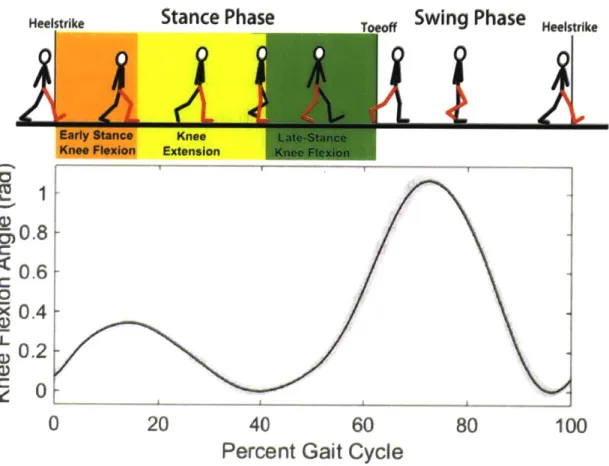
from heelstrike to the following heelstrike of a given limb. The gait cycle can be divided into two phases: stance phase (-60% of the GC) is defined as when the foot is on the ground, from heelstrike to toeoff, and swing phase (-40% of the GC) is defined as when the foot is off the ground, from toeoff to the subsequent heelstrike. The stance phase may be further divided into sub-phases. For the purposes of this thesis, the knee behavior is described. After heelstrike, during loading response, the knee flexes in early stance flexion as it helps to absorb the initial impact, while providing an extensor moment for support. The knee then extends during mid-stance, in knee extension as the torso progresses up and over the stance limb, and the knee begins to produce a flexion moment to slow this progression. Finally, in late stance flexion, defined from mid-stance maximum knee extension to toeoff, the knee flexes in preparation for lifting the leg into the air for the swing phase.
This last phase of stance, late stance flexion, is particularly important in the present work, since transtibial amputees walking with conventional prostheses exhibit increases in hip power during this phase of gait, possibly in response to the lack of power from the calf muscles, including the gastrocnemius [4].
Heelstrike
Stance Phase
Swing Phase
HSI,,I,Early Stance Knee Flexion
0
Knee Extension20
Late-Stance Ktje Flexio40
Percent Gait
60
Cycle
80
100
Figure 4: Knee function in the human gait cycle for normal level-ground walking
-50.8
0.6
C 0*X 0.4
U_ 0 .2 C I I IChapter 3
Quasi-passive Artificial Gastrocnemius
3.1 Introduction
In order to develop appropriate assistive devices, it is important to first understand how the gastrocnemius muscle functions. In-vivo ultrasonography shows that the gastrocnemius muscle fascicle length is largely isometric during the early and mid-stance phases of level-ground walking [9], indicating that the passive tissues such as the Achilles tendon are responsible for much of the power delivery from the gastrocnemius. Hence, the gastrocnemius may be approximated by a clutched-spring, with the spring representing the compliant tendinous structures, and the clutch representing the isometrically-acting muscle fibers. Indeed, a model of human gait by Endo and Herr with only spring-clutch structures at the knee joint was able to achieve human-like metabolic economy while capturing the dominant kinetic features of human walking [10]-[12]. It is therefore possible that a physical clutch in series with a spring can provide much of the missing knee function of the gastrocnemius in transtibial amputees.
Researchers have begun to study the effects of a robotic device at the affected-side knee to provide the knee flexion moment of the missing gastrocnemius. In the first such study [8], a knee orthosis, dubbed an artificial gastrocnemius (AG) was built, based on the spring-clutch representation of the gastrocnemius in the Endo-Herr model. This device was quasi-passive, in that it did not provide net positive mechanical power to the wearer, but still required an active controller and electrical power to operate. The AG was physically realized as clutchable rotary spring at the orthosis knee joint. Two copies of this AG, worn along with a powered-ankle-foot prosthesis (PAFP), was tested on both legs of one bi-lateral transtibial amputee, with promising results: the amputee's metabolic energy expenditure was reduced
with the AG-PAFP condition, compared to the amputee walking at the same speed with only conventional leaf-spring-type ankle-foot prostheses. However, since the PAFP was not tested independently of the AG, it is not clear what incremental effects the AG had over the PAFP alone. A need, therefore, exists, to evaluate the incremental biomechanical and metabolic effects of the AG knee component.
In this study, we hypothesized that applying a clutched-spring at the affected-side knee joint of transtibial amputees, in conjunction with a powered ankle-foot prosthesis, would reduce biological knee flexion moment of the affected-side knee joint, as compared to the same conditions with only the ankle-foot prosthesis with identical mass distribution. We expected that this reduction in knee flexion moment would stem from lower knee and hip moments and powers and associated reductions in hamstring muscle activity, and we further hypothesized that these changes would provide a corresponding reduction in metabolic cost of walking.
3.2 Methods
3.2.1 HardwareThe quasi-passive artificial gastrocnemius (QPAG) comprised a powered ankle-foot prosthesis to provide ankle function in the sagittal plane, and a clutched-spring joint, mounted on a knee orthosis on the affected-side knee. Together, these two devices represented a bi-articular prosthesis, which could act at both joints independently.
3.2.1.1 Powered Ankle-Foot Prosthesis
A BiOM powered, ankle-foot prosthesis (BionX, Bedford, MA), shown in Figure 1,
was used as the prosthesis for all clinical trials. This prosthesis had the capability of providing positive net power at levels comparable to the human ankle-foot complex [5]. At the core of the prosthesis was a series elastic actuator, comprising a brushless DC motor, ballscrew, and carbon fiber leaf spring. For dorsiflexion angles,
a rigid hard-stop engaged, both to reduce the torque required by the motor in dorsiflexion, and to act as a safety feature in the event of a power failure. The total mass of the prosthesis and battery was 1.8 kg.
The prosthesis controller employed a positive force feedback strategy, which served to approximate the biological muscle dynamics and neural reflexes. A wireless communication link enabled real-time tuning of the control parameters.
Lateral - Medial
Soleznoid Pt :t i4Ietedr Sok"oil Solenoid Rotaiting Translating Rotating
unitger Sle Plate Clutch Ring Clutch Ring RetumHousing
Ri..rn (Medial)
ONOin ...
Solenoid 1atcral
Cover Cage .earing Spring Spnng Housing Medial it
Attacluneng (Lateral) BtBearing
Figure 5: Joint mechanism of the quasi-passive artificial gastrocnemius
The exploded view of the joint design (bottom) is shown along with a rendering of the assembled joint without the cover (top).
Thigh Cuff Polycentric Orthosis Joint Spring-Clutch Linear Bearing Socket Achchment Bracket Radial Bearing
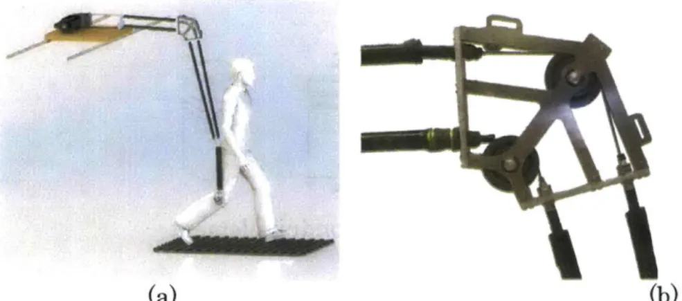
Figure 6: Quasi-passive artificial gastrocnemius
3.2.1.2 Clutch-Spring Joint
The QPAG, shown in Figure 6, was a knee orthosis, comprising a pair of polycentric hinges that connected a thigh cuff to an aluminum bracket. The bracket connected to the base of a participant's socket, between the prosthetic pylon attachment and the socket. A custom, dog-tooth rotary clutch-spring with series compliance was attached lateral to the knee, in parallel with the hinges.
This clutch-spring joint was based on the design by [13], but had the addition of series compliance. It included two rings of 90 dog teeth each, brought together by the action of a solenoid. As in Figure 5, the clutch controlled the relative rotation of the Housing to the Rotating Clutch Ring. A solenoid was built into the middle of the joint, and translated in the medial-lateral direction under action of its actuation power and a return spring. When the solenoid was energized, the Translating
Clutch Ring was engaged with the Rotating Clutch Ring. The translating clutch plate constrained the rotation of the Rotating Plate, which in turn was connected to the Housing through two tangential linear compression springs. Thus, when the solenoid was energized, the Housing was coupled to the Rotating Clutch Ring
through the springs, and when the solenoid was inactive, these two parts were free to rotate with respect to each other.
The Housing of the clutch was bolted to the thigh cuff of the knee orthosis. The Rotating Clutch Ring connected to an output link with a linear ball bearing and radial ball bearing, acting in series. These bearings accommodated for the kinematic difference between the polycentric hinges of the orthosis and the single-axis rotation of the clutch joint (Figure 6). The total weight of the orthosis, including battery and electronics, was 1.9 kg.
The QPAG had onboard sensing for use in the control algorithm. Knee angle of the
QPAG
was measured using a 10 kOhm rotary potentiometer. Torque provided by the spring-clutch element was estimated by measuring the deflection of one of the two identical tangential springs with an 8 kOhm linear potentiometer. Prosthesis-side ground contact was detected using a resistive pressure sole footswitch (model:FSW, B&L Engineering, Santa Ana, CA), inserted into the shoe between the
prosthetic foot and the insole.
3.2.2 Modeling and Spring Stiffness Selection
The selection of the spring constants for the tangential springs allowed for the control of rotary stiffness of the clutch-spring element. It was desirable for the stiffness of the clutch-spring joint to be such that the spring-clutch behavior of the artificial gastrocnemius would most closely reproduce the gastrocnemius muscle behavior of a healthy gastrocnemius. To this end, walking data from healthy non-amputees was used to select the spring stiffness values for the spring-clutch joint.
3.2.2.1 Target Biological Behavior
Kinetic and kinematic walking data were collected at the Gait Laboratory of Spaulding Rehabilitation Hospital, Harvard Medical School, in a study approved by the Spaulding committee on the Use of Humans as Experimental Subjects. A
healthy adult male (81.9 kg weight, 1.89 m height) was asked to walk at self-selected walking speeds across a 10 m walkway in the motion capture laboratory after informed consent was given. The motion-capture was performed using a VICON 512 motion-capture system, comprising eight infrared cameras. Reflective markers were placed at 33 locations on the subjects' bodies in order to allow the infrared cameras to track said locations during the trials. The cameras were operated at 120 Hz and were able to track a given marker to within approximately 1 mm. The markers were placed at the following bony landmarks for tracking the lower body: bilateral anterior superior iliac spines, posterior superior iliac spines, lateral femoral condyles, lateral malleoli, forefeet and heels. Wands were placed over the tibia and femur, and markers were attached to the wands over the mid-shaft of the tibia and the mid-femur. Markers were also placed on the upper body at the following sites: sternum, clavicle, C7 and T10 vertebrae, head, and bilaterally on the shoulder, elbow, and wrist joints. Ground reaction forces were measured using two staggered force plates (model no. 2222 or OR6-5-1, by Advanced Mechanical Technology Inc. Watertown, MA, USA), which were incorporated into the walkway. The precision of these force plates in measuring ground reaction force and center of pressure was approximately 0.1 N and 2 mm respectively. The force plate data was collected at 1080 Hz and synchronized with the VICON motion capture data.
3.2.2.2 Target Musculoskeletal Model
A simulation of human walking was used to select the desired knee spring stiffness
of the QPAG. The parameters were optimized for the Endo-Herr sagittal-plane human leg model [11], [12], [14] using the method described in [8]. In this model, all muscle-tendon units, with the exception of the monoarticular hip flexors and extensors, and the monoarticular ankle plantar flexor were modeled as unidirectional spring-clutch elements (Figure 7), based on the hypothesis that these muscles largely behave isometrically during walking at a self-selected speed. The
remaining muscle-tendon units were modeled as unidirectional force sources in series with springs. When a given clutch was disengaged, it exerted no force, and the joint was allowed to rotate freely without any resistance from the corresponding spring element. Conversely, when a given clutch was engaged, its series spring would produce a force proportional to the spring deflection if the spring-length was greater than the spring's rest-length, and zero force otherwise. The spring forces were applied to the respective joints via moment arm lengths from literature [15]. For the purposes of the AG spring selection, this model was modified to simulate a transtibial amputation. The ankle joint was removed, and the biarticular gastrocnemius spring-clutch element was modified to be a monoarticular knee flexor, as a representation of the QPAG knee joint (Figure 8).
dutch
oCn JWit
Contracile element
Figure 7: The Endo-Herr leg model using quasi-passive elements Figure credit: Ken Endo PhD thesis [14].
Artificial -AWv- Spring -). Pin joint
gastrocnemius -- _ Clutch -qW Contractile element
Figure 8: Quasi-passive leg model with monoarticular gastrocnemius spring Here, the biarticular gastrocnemius element was made into a monoarticular element for the purposes of modeling the knee component of the quasi-passive artificial gastrocnemius device. Figure credit: Ken Endo PhD thesis [14].
3.2.2.3 Optimization
The parameters of the modified musculoskeletal model were selected with an optimization aimed at producing simulated joint moments at the knee and hip that best matched those moments from non-amputee target walking data. The optimized parameters of the model included seven spring constants and five spring rest lengths. Joint kinematics for the knee and hip were used as input to the model, while the parameters were optimized to minimize the following cost function, which was minimized subject to the condition that the net hip moment from the simulation matched the biological moment data throughout the gait cycle.
2 100 ij ij
f(x) = ay Y bio sim + Wa (1)
j=1 i=1 bio
Here, x is a vector of the 12 stiffness and engagement parameters, 4jj, and -r'! are the joint moments applied about joint
j
at the ith percentage of the gait cycle from the biological data and the model, respectively. The parameter Wat is the totalpositive mechanical work performed by the hip force sources during the gait cycle, and a is a weighing coefficient. The value of a was made as low as possible (0.5) while not greatly reducing the R2 values.
3.2.3 Control
The quasi-passive artificial gastrocnemius produced no positive net mechanical work to the wearer, but still required a control system to determine the appropriate times to engage and disengage the clutch. This controller took knee joint angle and stance information as input, and engaged the clutch appropriately through each gait cycle. The clutch was controlled to engage at maximum stance knee flexion angle, enabling the spring to store energy during the subsequent knee extension and flexion into swing phase, as shown in Figure 9.
1.2
---0.8 0.6
-0.4 -Clutch Clutch
off Clutch Off
E0.2- On /
0
0 20 40 60 80 100 120
Percent Gait Cycle
Figure 9: Example action of the clutch engagement.
A typical knee flexion angle profile is shown for level-ground walking. The dashed red section indicates the region in the gait cycle when the clutch in the QPAG would be engaged.
3.2.3.1 Control Electronics
The computer platform for controlling the QPAG was a commercial single-board computer (model: Raspberry Pi Version B, Raspberry Pi Foundation,
Cambridgeshire, UK). The computer was equipped with an 800 MHz ARM11 processor, 512 MB SDRAM, with Linux Debian.
3.2.3.1 Control Algorithm
Finite State Machine
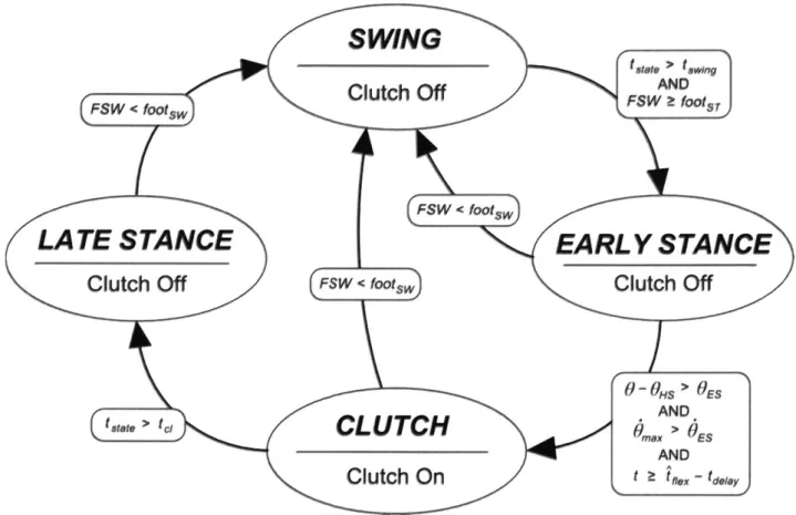
High-level control was implemented using a finite state machine, implemented in Python. The gait cycle was divided into four states: (1) SWING; (2) EARLY
STANCE (3) CLUTCHED; (4) LATE STANCE (Figure 10).
The SWING state was triggered from any other state when the affected-side foot left the ground, as detected by a drop in footswitch signal, FSW, to less than a fraction, footsw of the maximum possible signal. During SWING, the clutch was disabled, allowing the knee to swing freely.
The EARLY STANCE state was triggered from the SWING state at foot contact of the affected-side with the ground, defined as FSW increasing to the stance threshold, fOotST , provided that the time elapsed in the current state, tstate, was at least the minimum time required for the SWING state, tswing. During the EARLY
STANCE state, the clutch was disabled, and the controller monitored the knee
angle of the brace for maximum stance knee flexion, at which point the
CLUTCHED state would be engaged. A least-squares algorithm, similar to the one
used previously [16], continually predicted the time remaining before maximum knee flexion angle. This prediction provided time to initiate the engagement of the clutch, so that the clutch would be fully engaged as close as possible to the time of maximum knee flexion. In addition to this knee flexion detection algorithm, two safety features were in place to ensure that the motions detected were resulting from a walking gait. The CLUTCHED state could only be enabled if the following two conditions were also met: 1) the amount knee was flexed a minimum angle of
0ES from the angle at heelstrike, OHS, 2) the maximum knee flexion angular velocity,
and OES were experimentally determined during early testing as the lowest values that successfully prevented false-triggering of the CLUTCH state outside of a steady, level-ground walking gait.
SWING
Figue 1: Fnit stte mchie fr te qasi-assve rtiicil gstreius
Th CUTHD tae evet
Cttche
clutc nertemaiuANee exoFSW < footsw Cuc f s ~o,
FSW < footsw)
LATE
sta
ce
EARLY STAN E
Clutch Off FSW < footsw
Clutch Off
... ...0 -O H S > O E S
AND
t.tet > tc, CLUTC d,,,,, > ES AND
Clutch On
t z t f.ex- tdly,Figure 10: Finite state machine for the quasi-passive artificial gastrocnemius
The CL UTCHED state served to activate the clutch near the maximum knee flexion during stance phase of walking. This state was activated when the following criteria were met: 1) the maximum stance flexion angle was predicted to occur within the time tdelay of the current time, 2) the knee angle was flexed more than a threshold,
OES, and 3) the maximum knee flexion angular velocity, 0 during the EARLY
STANCE state exceeded a threshold OES.- Conditions 2 and 3 were used to
differentiate a walking gait with slow, non-gait motions, the latter of which did not warrant activation of the clutch.
The LATE STANCE state served to turn off the clutch after it engaged. Once the clutch spring began to develop force, the clutch teeth would bind, preventing the clutch from disengaging until the spring force dropped sufficiently. Therefore, to save electrical power and to allow a smoother clutch disengagement, the clutch solenoid was deactivated by entering the LATE STANCE state when the time elapsed in the current, CLUTCH, state, tstate, exceeded the clutch timeout threshold, tc1.
Parameter Description Value
fOOtsT Footswitch threshold for entering the EARL YSTANCE state; 0.2 fraction of the maximum possible value
footsw Footswitch threshold for entering the SWING state 0.15
tswing Minimum time in the SWING state before it is possible to exit 200 ms
SWING
OES Minimum knee flexion angle (rad) during the EARLY 0.087 rad
STANCE state before the clutch can be engaged
Minimum knee flexion angular velocity that must be observed
OES during the EARLYSTANCE state before the clutch can be 1.2 rad/s
engaged
tdelay Delay time required between activation of the solenoid and the 50 ms full engagement of the clutch
tcl Maximum time to energize the solenoid 400 ms
Table 1: Parameter values for the QPAG controller
Prediction Algorithm
In order to maximize spring energy storage and return, it was desirable to engage the clutch as near as possible to the moment of peak knee flexion in the EARLY
STANCE state. In fact, the clutch solenoid needed to be engaged slightly before the
desired clutching time, as to account for the time required to close the gap between the two sets of clutch teeth. To achieve the necessary prediction of peak stance flexion, a look-ahead algorithm was used.
First, the knee angle during the EARLY STANCE state was approximated as parabolic, given this assumption, the location of the vertex of the parabola may be found by performing a linear fit to the knee angular velocity data, via running sums, and solving for the zero-crossing. The algorithm used here was similar to one described by [16]. However, the earlier algorithm assumed a fixed time-step, which was not applicable with the system in this study, as the computer platform was not a truly real-time system. Hence, the algorithm proposed here did not presume a fixed time step.
The parameter
f
= [flfl
1] that minimizes the error in the least squares sense oflinear model f(t) = /0 + fl1x(t) to time-series data (x(t), y(t)) is
fl=
(XTX) XTy(2)
where the matrix X has elements Xj,1 = a- =
Expanding Equation 2 yields
Ex y+ x
]
(3)Wx2 - (ZX)2
For the task of estimating the angular velocity over time, the values of x were timestamps, and the values of y were knee angular velocity values. For the window of size W, the most recent W values of x and y were maintained in a queue. At each new timestep, the oldest values of x and y were popped from the queue while the current x and y values were added to the queue. This method allowed the sums to be updated each timestep without needing to store all values of the computed sums. Finally, the estimated time of the angular velocity zero-crossing was tf ex = -fl/Po. It was found experimentally that the minimum error in clutching-time between the initiation of the development of clutch torque and the peak knee flexion angle occurred when the clutch was engaged 50 ms prior to the predicted maximum knee angle. As a result, the time delay parameter, tdelay, was set to 50 ms.
3.2.4 Experimental Protocol
Two participants with below-knee amputation were involved in this study (Table 2). Both participants had right-side unilateral amputation and were of generally good health. The clinical evaluation was conducted at MIT (Cambridge, MA) and was approved by MIT's Committee on the Use of Humans as Experimental Subjects
(COUHES). Each participant provided written, informed consent was obtained from
before data collection was initiated.
Height (cm) Weight (kg)
Subject 1 (Sl) 180 93
Subject 2 (S2) 193 94
Table 2: Amputee participant body parameters
An infrared camera system (model T40s, Vicon Motion Systems Ltc, Oxford, UK) was used to track the three dimensional motion, recorded at 100 Hz, of reflective markers, placed at 47 anatomical locations on the participants' bodies, based on the Helen Hayes marker model. Ground reactions forces and center of pressure locations were measured using a dual-belt instrumented treadmill (Bertec
Corporation, Columbus, OH) with a sampling rate of 1 kHz. Electromyographic
(EMG) signals were collected at 2 kHz using a wireless surface system (Trigno,
Delsys Inc, Natick MA) for the semimembranosis, and vastus lateralis muscles. The net metabolic cost of walking during each condition was estimated using standard open-circuit gas exchange techniques (model: K4b2, COSMED, Rome, Italy).
At the beginning of each session, the participant was asked to don the powered prosthesis in place of their conventional prosthesis. The knee orthosis of the QPAG was then affixed to the prosthesis and donned by the participant. A short time period was given to ensure that both the prosthesis and the artificial gastroenemius orthosis were functioning properly.
For each participant, the prosthesis controller's power setting was adjusted using the commercial tuning app as the participant walked over a treadmill at 1.25 m/s so
as to achieve net work from the prosthesis per step that was within one standard deviation of the mean for non-amputees walking at the same walking speed [17]. It was verified that the level of prosthesis net work remained within the desired range for both walking conditions for a given participant (0.045 to 0.16 J/kg) and, more importantly, that this level of net work stayed reasonably consistent across walking conditions for each participant.
Both the powered prosthesis and artificial gastrocnemius were worn for all trials. The participants were asked to perform one standing trial to measure standing metabolism. Walking trials were performed on the treadmill at a speed of 1.25 m/s. Two walking conditions were tested: 1) a baseline condition (BASELINE) in which the QPAG acted as a free-joint at the knee with the spring-clutch disabled, and 2) an active condition (ACTIVE), in which the QPAG was controlled as a clutched spring at the knee with the described control algorithm. For both conditions, the powered ankle-foot prosthesis was active. The BASELINE condition represented a monoarticular transtibial prosthesis, as the knee joint was a free-joint when the clutch was inactive. Yet the mass distribution of the device was identical to the ACTIVE condition. Thus, a direct comparison could be made to determine the incremental effects of the clutched-spring knee joint.
3.2.5 Data Processing
Fourth-order Butterworth filters were used to filter the marker position and ground reaction force data with 6 Hz and 25 Hz cutoff frequencies, respectively. The marker and force data were post-processed through the SIMM (Musculographics Inc., Evanston, IL) inverse dynamics module to produce joint moments and angles in three dimensions. Only sagittal plane dynamics were considered. Affected-side biological knee moment contribution was computed by subtracting the measured
QPAG
knee moment from the total knee moment estimated from the inverse dynamics.Gait events were determined using vertical ground reaction force data from the embedded forceplates. Approximate event timing was found by determining the times when the force increased beyond a 40 N threshold. Exact heelstrike and toeoff times where found by progressing backward, and forward in time, respectively, until the force value dropped to zero. Data were then cut to gait cycles based on heelstrike times, and resampled to 101 points. Gait cycles were discarded for the beginning and end of each trial, during the speed transients of the treadmill. Gait cycles in which the stride times were below 0.7 seconds or above 1.3 seconds, or in which a foot crossed the mid-line of the treadmill were also discarded.
Joint powers were computed as the product of joint moments and joint velocities from SIMM-derived joint kinematics, where positive power was defined as that produced by the joint on the environment. Positive joint work during late stance knee flexion was computed as the positive contribution of the time-integral of joint power from maximum stance knee flexion to toeoff. This region of the gait cycle was chosen for analysis because, as the knee flexes from the maximum extension angle, it provides an opportunity for the AG to provide positive power to the wearer. Joint flexion moment impulse was computed using the same integral for joint flexion moment. Net prosthesis work was computed by integrating the SIMM-derived joint torque over joint angle over the gait cycle.
Amputee EMG signals were first processed internally by the EMG system by applying a 4th-order bandpass filter with a pass band from 20 Hz to 450 Hz. Any DC offset was removed, and the signals were then rectified, and smoothed using a 3 Hz, 3rd-order Butterworth filter. The EMG data were then cut to gait cycles and averaged in the same manner as the motion and force data. The resulting EMG data were then normalized so that the average values of the activation signals matched those from [18] during the range of activation for the literature data. For each subject and walking condition, the EMG signals were averaged over the period, when the spring-clutch was, on average, engaged and generating torque.
Metabolic cost for each walking speed was computed by taking average oxygen and carbon dioxide data over a two-minute window at the end of each six-minute trial. The metabolic power was computed using the equation
P = K0 2 V0 2 + Kco02Vco2 (4)
where P is the metabolic power in Watts, V02 is the volume flow rate of Oxygen
inhaled, IC02 is the volume flow rate of carbon dioxide exhaled, and K0 2 and Kco2 are constants with values from literature [19], given as K 0 2= 16,580 W/L and Kco2=
4,510 W/L. The above equation is only valid for conditions when the metabolism is primarily aerobic. As a verification of this condition, the respiratory exchange ratio (RER), defined as VC0 2/ V02 was monitored, and only metabolic results with RER
values less than 1.1 were considered.
3.3 Results
3.3.1 Modeling
The spring stiffness of the clutched-spring gastrocnemius element, derived from the modeling, was 101 Nm/rad [8]. To produce this rotary stiffness about the knee joint, two linear compression coil springs were selected, each with 51 N/mm stiffness. These springs acted on the joint with a moment arm of 32 mm, causing the equivalent joint rotary stiffness to be 105 Nm/rad.
3.3.2 Ankle Prosthesis Net Work
As shown in Table 3, the net work produced by the powered ankle-foot prosthesis was within the desired range from literature.
BASELINE (J/kg) ACTIVE (J/kg) Subject 1 0.113 +/- 0.028 0.130 +/- 0.024
Subject 2 0.077 +/- 0.016 0.082 +/- 0.019
Table 3: Net work per step by the powered ankle-foot prosthesis with the
QPAG
The net work values were kept within the literature range of 0.045 to 0.16 J/kg.3.3.3 Affected Knee Kinematics
Plots of the affected-side knee angle are shown in Figure 11. A reduction in peak knee extension angle was observed during mid-stance phase for both subjects (average angle reduction of 0.047 radians), with the ACTIVE condition producing an increased flexion angle, compared to the BASELINE condition.
BASELINE (rad) ACTIVE (rad) Difference (rad) Subject 1 0.184 +/- 0.030 0.240 +/- 0.027 +0.056 Subject 2 0.019 +/- 0.015 0.057 +/ 0.024 +0.038 Table 4: Affected-side peak stance knee extension with the QPAG.
Peak angle values for both walking conditions are shown, as well as a difference value, which was computed by subtracting the BASELINE value from the ACTIVE value. 1.2 1 0.8. 0.6-0.4 0.2--0.2 0 2 Subject 1 0 40 Percent 1,2 I I I I I I / I I' 4 60 Gait Cycle 80 100 0 C 2 .d 0s 0.8 0.6 0.4 0.2 0 -0.2 LL 0 20 Subject 2 4. 40 60
Percent Gait Cycle
Figure 11: Affected-side iknee kinematics with the QPAG
shown for the BASELINE condition where the clutch was disabled (thick solid blue line), the active condition (thin solid red line). For reference, biological knee moment data are also shown for the non-amputee from which the clutch spring was tuned (thick black dashed line) +/- 1 standard deviation (black dotted lines). The vertical
lines indicate the typical engagement and disengagement times for the clutch.
0 C C x 0 80 100 I