HAL Id: hal-01366686
https://hal.archives-ouvertes.fr/hal-01366686v2
Submitted on 14 May 2019HAL is a multi-disciplinary open access
archive for the deposit and dissemination of sci-entific research documents, whether they are pub-lished or not. The documents may come from teaching and research institutions in France or abroad, or from public or private research centers.
L’archive ouverte pluridisciplinaire HAL, est destinée au dépôt et à la diffusion de documents scientifiques de niveau recherche, publiés ou non, émanant des établissements d’enseignement et de recherche français ou étrangers, des laboratoires publics ou privés.
Hyperbolic-by-design self-assembled metamaterial based
on block copolymers lamellar phases
Xuan Wang, Kevin Ehrhardt, Clemence Tallet, Marc Warenghem, Alexandre
Baron, Ashod Aradian, Mortem Kildemo, Virginie Ponsinet
To cite this version:
Xuan Wang, Kevin Ehrhardt, Clemence Tallet, Marc Warenghem, Alexandre Baron, et al.. Hyperbolic-by-design self-assembled metamaterial based on block copolymers lamellar phases. Op-tics and Laser Technology, Elsevier, 2017, 88, pp.85-95. �10.1016/j.optlastec.2016.08.005�. �hal-01366686v2�
1
Hyperbolic-by-design self-assembled metamaterial based on block
copolymers lamellar phases
Xuan WANG
a,b, Kevin EHRHARDT
a,b, Clémence TALLET
a,b, Marc WARENGHEM
c,d,
Alexandre BARON
a,b, Ashod ARADIAN
a,b, Morten KILDEMO
e, Virginie PONSINET
a,b*
a
CNRS, Centre de Recherche Paul Pascal, UPR 8641, 115 Avenue Schweitzer, 33600
Pessac, France
b
Univ. Bordeaux, Centre de Recherche Paul Pascal, UPR 8641, 115 Avenue Schweitzer,
33600 Pessac, France
c
Université Lille Nord de France, 59000 Lille, France
dUniversité d'Artois, Unité de Catalyse et de Chimie du Solide, UMR 8181, 62307 Lens,
France
e
Physics Department, NTNU, Høgskoleringen 1, 7491 Trondheim, Norway
*author for correspondence: Virginie PONSINET,
[email protected]
,
Citation: Hyperbolic-by-design self-assembled metamaterial based on block copolymers
lamellar phases, Xuan Wang, Kevin Ehrhardt, Clémence Tallet, Marc Warenghem, Alexandre
Baron, Ashod Aradian, Morten Kildemo, Virginie Ponsinet, J. Opt. & Laser Techn. 88, 85-95
(2017), DOI:10.1016/j.optlastec.2016.08.005
KEYWORDS: plasmonics, self-assembly, hyperbolic media, block copolymers, localized
surface plasmon resonance, effective dielectric permittivity, lamellar phase
Abstract :
Hyperbolic metamaterials use the concept of controlling the propagative modes through the engineering of the dispersion relation, and are considered highly promising to reach different meta-properties. Here we propose a novel bottom-up fabrication technique for uniaxial anisotropic metamaterials presenting a strongly anisotropic dispersion relation in the visible wavelength range, using self-assembled nanostructured block copolymers hybridized with gold nanoparticles. The materials consist in periodic lamellar stacks of period 28 nm, of alternating layers of pure polymer (dielectric) and layers of composite of polymer loaded with a high density of 7 nm gold nanoparticles. The spectral variation of their anisotropic effective dielectric permittivity is determined by variable-angle spectroscopic ellipsometry using appropriate effective medium models, as a function of the density of plasmonic nanoparticles. For large gold loading and close to the plasmon resonance of the nanoparticles, the lamellar stack presents ordinary and extraordinary components of the dielectric function of opposite signs. We therefore demonstrate for the first time the possibility of using a self-assembly methodology for the fabrication of bulk hyperbolic metamaterial.
2 Introduction
The breakthroughs and innovations in the information and communication technologies rely, to a large extent, on improved performances of the devices, and their constitutive materials. Optical metamaterials lie among these envisioned breakthroughs in the near future: they are artificial materials structurally designed with the purpose of producing extraordinary optical properties. Their potential in revolutionizing the optical technologies has been largely recognized1,2,3. While precise control of both the dielectric permittivity () and the magnetic permeability () of a 3D artificial material, in the visible or infra-red ranges, would open access to transformation optics and negative index materials, leading to the capacity of engineering the propagation of light in devices in an unprecedented manner2, these goals are still far from reach. On the other hand, by combining nanostructuration and anisotropy, it is possible to engineer novel and non-natural dispersion relations, in order to control original propagation properties. This is why a recent interest has focused on a special case of uniaxial anisotropic metamaterials, called hyperbolic materials4 , 5 , 6 , 7, which exhibit strongly anisotropic dispersion relations in the visible or infra-red wavelength range. These materials are considered amongst the most promising metamaterials, because of their ability to provide a multi-functional platform4 to reach different meta-properties.
For example, hyperbolic nanowire and lamellar stacked metamaterials have been studied theoretically and experimentally4,6,8,9. Such structures have displayed a variety of promising properties, generating a surge in the activity on the topic over the recent years: negative refraction10, super-resolution11, sub-wavelength modes12, perfect multi-band absorption13, optical topological transition14, epsilon-near-zero light propagation15, spontaneous emission and Purcell effect enhancement16,17,18,19,20, thermal emission engineering21 including super-Planckian regimes 22, or biosensing23,24.
One very attractive property is the so-called “super-resolution” (i.e., sub-diffraction imaging), because the required structures are relatively less demanding than other metamaterials, and because super-resolution could be profitable to several technological fields. Optical microscopy is indeed an essential tool in many fields such as microelectronics, biology and medicine. It is, however, hindered by the intrinsic diffraction limitation as it cannot obtain a better resolution than half the wavelength of light. This is because the finer detail-carrying, high wavevector components of the field emitted from the object are evanescent, decay exponentially in a medium with positive permittivity and permeability, and cannot contribute to the subwavelength image formation. Near-field scanning techniques25, and fluorescence-based imaging methods26 have put forward ways to circumvent this limitation and have brought optical microscopy into the nanoworld, with the fascinating and revolutionary goal to visualize the pathways of individual molecules inside living cells27. Similar intrinsic resolution limitations also hinder optical lithography, one of the most important tools equipping the semiconductor industry, ubiquitous in our societies.
In hyperbolic materials, two components of the dielectric permittivity tensor have opposite signs, as if the material behaved like a metal (i < 0) along at least one direction and like a dielectric (j > 0)
3
along at least another. Let us consider a uniaxial material with principal axes (x,y,z) and permittivity tensor z 0 0 0 0 0 0 // //
with
//
//’ + i
//” and
z
z’ + i
z” Equation 1where the parallel (//) symbol denotes the (x,y)-plane. The isofrequency dispersion relation in this material is4,28
( ) // 2
0 2 // 2 2 2 // 2 2 o o z z z y x o o y x k k k k k , Equation 2where the two terms describe the behavior of waves of different polarizations: polarization in the (x,y) plane for the first term and polarization in a plane containing the z direction for the second.
The latter can be written 2 // 2 2 2 o z z y x
k
k
k
k
, with ko2oo2 Equation 3It exhibits a hyperboloid branch when the product
//'
z'
0
, contrary to dielectrics, for which this relation defines a closed ellipsoidal shape (spherical if isotropic). This peculiar shape allows notably for the propagation of large magnitude wavevectors, carrying details finer than half the wavelength, otherwise corresponding to evanescent non-propagative waves in a usual dielectric. Hyperbolic material fabrication usually relies on metal deposition within top-down produced uniaxial nanostructures, either lamellar or cylindrical, and their permittivity tensor is usually inferred from basic effective medium models. The spectral tunability of the effective medium properties of the material is limited by the large spectral dispersion of the optical properties of the metal, which generally follows the Drude model.One of the main bottlenecks in the research on metamaterials and hyperbolic materials in particular remains the lack of robust, simple and large scale fabrication technologies which permit tailoring final optical properties at chosen frequency ranges (including visible frequencies), and setting the technological basis for the development of devices: the field is open to innovative fabrication proposals. The powerful 'top-down' techniques such as nanolithography have been successful in manufacturing nanostructured surfaces and in evidencing meta-material properties, such as hyperlensing29 and cloaking1, at wavelengths larger or close to the visible domain30 and even at ultraviolet frequencies31. The use of chemistry and self-assembly of metallic nanoparticles, acting as plasmonic resonators, into dense ordered structures, was anticipated as a promising ‘bottom-up’ alternative32 , 33, especially in order to produce large-scale, 3D and tunable metamaterials. The versatility of chemical synthesis and the diverse mechanisms of self-assembly can be combined to produce materials with both nanostructuration and anisotropy, presenting novel propagation properties in the visible or infrared ranges.
4
In particular, diblock copolymers34,35 have long been known to self-assemble into nanomaterials with strong structural anisotropy. They are macromolecules made of two molecular chains of distinct chemical nature linked together, called the blocks, and present solid state spontaneous organizations with long-range order and tunable characteristic sizes, ranging typically from a few nanometers to a few hundred nanometers. The morphology is selected mostly in relation with the volume fractions of the blocks fA and fB=1 – fA, due to interfacial curvature effects
35,36
, among the choice of body-centered cubic array of spherical cores, bicontinuous gyroid, hexagonally packed cylinders and lamellae. It is thus largely possible to design a desired material by choosing the chemical nature and the length of the blocks in order to obtain a given morphology, a given characteristic size, as well as a given chemical functionality. Using such ordered block copolymer phases for optical applications is limited by the usually low dielectric contrast between the blocks: the refractive index of almost all easily accessible polymers is in the range 1.48 – 1.61. One way of improving the contrast, among others37,38, or of conferring specific optical properties, is to disperse adequate nanoparticles within the ordered polymer phase in such a way that the particles get ordered by the matrix. This is what is reported in this work, in which we show that nanocomposites based on metal nanoparticles embedded in a dielectric host, can present a strongly anisotropic structure, as well as spectrally selective optical anisotropy, as a consequence of the spectral tunability of the plasmon resonance.
Indeed, we propose in this article a novel fabrication technique for lamellar metal-dielectric nanocomposites using self-assembled block copolymer nanostructures, and we demonstrate the relevance of such bottom-up methodology for the fabrication of hyperbolic metamaterials. We first describe the preparation and structural study of thin films of self-assembled nanocomposites of block copolymers and gold nanoparticles prepared by wet chemistry. We then present the study of the relation between the structure of the composites, and in particular the density of the gold nanoparticles, and the anisotropy of their effective dielectric permittivity tensor, which is extracted from variable-angle spectroscopic ellipsometry. We finally discuss the hyperbolic nature of the self-assembled material.
I. Nanostructure design and fabrication
As a first requirement, a structural uniaxial symmetry appears highly desirable, in order to obtain a hyperbolic regime of optical anisotropy. Diblock copolymer thin film engineering39,40 offers a genuine technological platform for the generation of nanostructured thin films with different morphologies of the domains. Two specific thin film morphologies are particularly attractive here, which present a high degree of order and a uniaxial symmetry: the lamellar phase in parallel alignment, which we study in the following, and the phase of hexagonally-packed cylinders in perpendicular orientation, which has been considered for applications including lithography masks41,42,43 and enhanced patterned LEDs44. A second requirement, for the light propagation properties to be described by a homogenized dispersion relation, is that the internal structure of the material presents a subwavelength characteristic size:
5
do << . This can be easily achieved with self-assembled block copolymer structures, with an appropriate choice of the total chain length.
We have studied several poly(styrene)-b-poly(2-vinyl pyridine) (PS-P2VP) copolymers, of different block lengths. A small-angle X-ray scattering study of thick samples of these copolymers (see Supplementary Information, Figure S1) shows the signatures of phases of either stacked lamellae or hexagonally-packed cylinders, depending on the ratio between the block lengths. The characteristic structural sizes, as given by the center-to-center distance between P2VP domains, range from 37 to 84 nm. As expected35, a lamellar nanostructure is obtained when both blocks have similar volume fraction
fA ~ fB ~ 0.5. Finally, we choose to work with the lamellar PS-P2VP copolymer with both blocks of
molar mass 25 kg/mol, which spontaneously develops a multilayered structurally uniaxial thin film of alternate poly(styrene) and poly(2-vinyl pyridine) layers with a period of 37 nm in the bulk. We use a process combining spin-coating of a relatively dilute polymer solution on a selective surface (silicon wafer having a higher affinity for P2VP rather than PS) and thermal annealing, which produces a flat and homogeneous film with a parallel alignment of the organized structures, throughout the thickness of the film between 200 and 700 nm. This ordered structure spans an area as large as the spin-coating process can produce (we use 15x15 mm² wafers).
The third requirement to obtain a hyperbolic medium, which is not provided by the simple copolymer self-assembly, is to induce dielectric permittivity of opposite sign depending on the probed direction. Thus, the combination of a metallic response (
< 0) and a dielectric response (
> 0) is necessary. Reported examples of multilayer hyperbolic materials have been fabricated by alternate deposition of metal and dielectric materials by electron-beam or sputter deposition in vacuum. A self-assembled block copolymer lamellar phase equivalent requires a pseudo-metallic nature for one of the layer types, which we obtain by doping one of the polymer phase with metallic nanoparticles, thus producing alternate stacks of pure polymer layers (polystyrene, referred to as PS in the following), and composite layers of gold nanoparticles and poly(2-vinyl pyridine) (referred to as NC for Nano-Composite layers) (see Figures 1 and 4).The optical properties of nanocomposites of gold particles and polymer with no order, equivalent to the NC layers of the lamellar stacks, have been studied previously, using spectroscopic ellipsometry. We showed that such nanocomposite films present a plasmon resonance due to the metallic nanoparticles45 and that the resonance amplitude increases as the gold volume fraction in the nanocomposite increases. As the resonance deepens, the system will ultimately reach
< 0 in some frequency range: in fact, the Maxwell Garnett Effective Medium Approximation (MG-EMA), although not truthfully applicable for such high-fractions, suggests this can roughly occur for gold volume fractions beyond 25%. In order to transform one of the block copolymer domain into such a pseudo-metallic nanocomposites, we can choose among several routes46,47,48 for selective nanoparticle incorporation. Here, we developed an impregnation methodology, adapted from the literature49,50, in which a previously ordered and aligned sturdy copolymer nanostructure can be selectively swollen6
with a precursor solution. More precisely, the film-bearing wafer is dipped into an Au salt (HAuCl4)
solution and then into a reducing agent (NaBH4) solution. Due to the strong insolubility of PS in polar
solvents, on the one hand, and the strong affinity of P2VP to Au, on the other hand, Au nanoparticles form selectively within the P2VP layers, thus producing a structure of alternating pure PS and (NC) (Au nanoparticles:P2VP nanocomposite) layers. One of the advantages of this infiltration procedure is that we can slowly increase, in a controlled way, the volume fraction of nanoparticles in the (NC) layers, by repeating the double dipping process N times. Each cycle increases the purple color of the film, related to the localized surface plasmon resonance of the nucleated gold nanoparticles. Structural and optical studies of the film were performed at different steps along the fabrication process, so that the same film was investigated for different values of N, which we will refer to in the following as “kinetic” measurements.
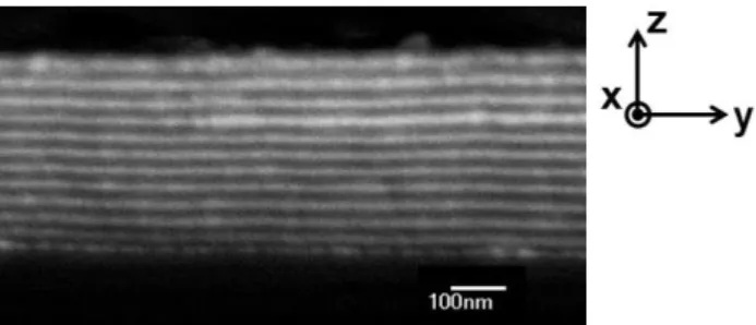
Using scanning electron microscopy (SEM), we fully characterize the structure of the studied multistack films. As can be seen on an example for N=5 (Figure 1), SEM observation clearly evidenced the contrast in electron density between adjacent layers in the multilayer film, which can unambiguously be attributed to the selective gold loading of the P2VP layer. More precisely, the film is composed of 9 bilayers (PS)+(NC) of thickness 14 + 14 = 28 nm, with an additional (NC) layer of 6 nm along the substrate surface and an additional (PS) layer of 6 nm along the air interface51. As demonstrated by the SEM images, the films are structurally uniaxial and homogeneous and we can define their dielectric permittivity tensor with the ordinary (parallel to the substrate,
ord =
) andextraordinary (normal to the substrate,
extraord =
z) components.
Figure 1. Backscattering scanning electron microscopy side-view image (SEM) of
a 370 nm-thick film of alternating layers of poly(styrene) (PS, appearing black) and Au nanoparticles:P2VP nanocomposite (NC, appearing white). The lower and
upper black domains of the micrograph are the substrate and the air, respectively. The trihedral indicates the ordinary ((x,y) or //) and extraordinary (z) directions.
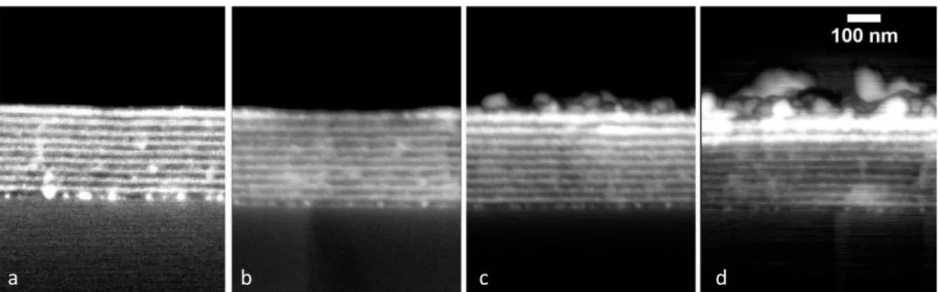
We can follow the structure of a sample as the amount of gold is increased in the film, by repeating the cycle of salt impregnation and reduction within the lamellar matrix N times. Figure 2 presents the evolution of the structure as followed by SEM. We can thus check that the lamellar structure is preserved and unchanged for all values of N for which the film was imaged. The contrast of the images cannot be quantitatively compared to confirm the increase of the gold volume fraction. It is noteworthy that the thickness of the NC layers does not show any detectable increase upon gold
7
loading with increasing N. This can be understood as due to a reorganization of the polymer chains conformation, as when such films are swollen with solvent, as well as a possible degradation of the P2VP segments involved in the chemical reduction of the gold salt. Beyond N=20, the SEM micrographs show the evidence of an uncontrolled gold deposit on the upper surface of the film.
Figure 2. Backscattering scanning electron microscopy side-view image (SEM) of
the 265 nm-thick film of alternating layers of pure polymer (PS, appearing black) and of Au nanoparticles:P2VP nanocomposite (NC, appearing white), for a number of cycles of gold impregnation and reduction of N=5 (a), 10 (b), 20 (c), 30 (d).
In order to gain more precise information on the shape and nature of the gold objects introduced within the lamellar stack, which SEM images do not provide due to lack of resolution, we performed complementary studies by transmission electron microscopy (TEM) as well as SAXS on dispersions obtained by full dissolution of the samples in a good solvent of the diblock copolymer at the end of the fabrication process. Both techniques show that the NC layers are composed of individual gold nanoparticles (NPs) of relatively homogeneous size (diameter D ~ 7 ± 2 nm). Figure 3 shows an example of the results obtained by TEM in the case of N = 25. We can therefore infer that such 7nm-gold NPs are dispersed with no specific order and surrounded by a P2VP matrix, in the NC layers.
Figure 3. Transmission electron microscopy (TEM) image obtained with a grid on which was
deposited a drop of the dispersion obtained by full dissolution of a film, at the step N = 20 of the fabrication process, in a good solvent of the diblock copolymer. The image evidences gold nanoparticles of mean diameter 7 nm. Note that this observation technique being destructive, it was performed on different samples than the ones studied by SEM and VASE.
8 II Methodology for the extraction of the optical properties
II.1. Experimental details
We study the samples using variable angle spectroscopic ellipsometry (VASE) in reflection with a phase modulated spectroscopic ellipsometer on the spectral range [450 - 1900 nm] (UVISEL from Horiba Scientific). We use the UVISEL II (A=45°; M=0) and UVISEL III (A=45°; M=45°) configurations, where A and M denote the azimuthal orientations of the input polarizer and photoelastic modulator, respectively, with respect to the plane of incidence. We acquire the ellipsometric quantities Is = sin2sin, Ic = sin2cos and Ic’ = cos2, where and are the two ellipsometric angles, defined by
r
p/r
s = tan ei
, with
r
p andr
s the complex reflection coefficients of the amplitude of the p-polarized (i.e., in the plane of incidence) and s-polarized (perpendicular to the plane of incidence) waves respectively. Three values of the incidence angle o=55°, 65° and 75° wereused and analyzed simultaneously. The spot size was 1 mm and the measured data were checked to be similar at three different locations on the samples. It is noted that the spectroscopic ellipsometry (SE) experiment in this configuration only probes low modulus wave-vectors with
k
x
k
osin
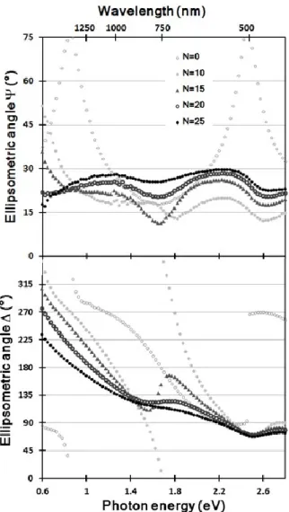
o.The “kinetic” VASE information was obtained by recording the full spectra every five gold loading cycles. This turns out to be very important information about the stacked structure as it is progressively evolving upon increased gold absorption in the layers. The VASE data, for one studied film, are shown on Figure 4, where the ellipsometric angles and are plotted for o=65° as a
function of the photon energy between 0.6 and 2.8 eV, and for increasing values of N between 0 and 25. For the initial lamellar structure (before infiltration, N = 0), one can see periodic oscillations typical of interferences driven by reflections at the air/film and film/substrate interfaces, as both PS and P2VP polymers are transparent in the studied energy range. As N is increased, the extrema shift toward lower energies and the fringe spectral separation decreases indicating an evolution possibly combining an increase in the total film thickness and a change in the effective dielectric function of the NC (Au nanoparticles:P2VP) layers. Moreover, their amplitude decreases markedly as the volume fraction of Au increases and the absorption of light by the LSPR and interband transitions in Au nanoparticles becomes dominant. Nevertheless, the interference features are damped but not rubbed out after successive infiltrations, showing that light does still travel through the film thickness and that the material remains at least partially transparent in this spectral range.
The data were analyzed using both the DeltaPsi2 software from Horiba Scientific and the Complete Ease Software from JA Woolam Company. SE data measured on the bare silicon substrate were analyzed using the Si and SiO2 tabulated dielectric functions and yielded a thickness value (2.0 nm)
for the native silica layer on the surface, which was fixed in the further analysis. SE of the PVP-PS diblock copolymer film, before gold introduction, gave the initial thickness, and demonstrated a finite amount of depolarization quantified by 2 2 2
1 Is Ic Ic'
PD , which could be well modeled as a
9
through-out the fits. One of the possible causes for this thickness non-uniformity is the presence of thickness defects observed on block copolymer thin films when the total thickness of the film is not exactly commensurate with the lamellar period: T = n do or T = (n+1/2)do, where n, a small integer, is
the number of complete bilayers 52,39,53,54.
Figure 4. Evolution of the measured ellipsometric angles and as a function of the photon energy for an angle of incidence of o=65° and different values of N
between 0 and 25. The spectroscopic features are damped as N increases, due to the increasing absorption of the film.
II.2 Ellipsometric modelling.
In order to extract the effective optical properties of the studied films from the SE data, two different models were built (see Figure 4). Due to the small sizes with respect to wavelength of both the gold NPs D ~ 0.02 and the copolymer nanostructure lamellae do ~ 0.05 at = 500 nm, an effective
medium (EM) description is appropriate, for all or part of the multilayer stack. The models are built using the information on the layer thicknesses, appropriate interface layers and number of bi-layer
10
repetitions inferred from the SEM images and schematized in Figure 5.a. The N-dependent dielectric functions of the polymer-gold nanocomposite effective media NC and EM2 were “kinetically” analyzed, meaning in consistency with a progressive evolution with increasing N, in order to refine the initial guesses.
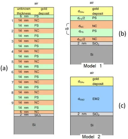
Figure 5. The models are built based on the detailed film nanostructure obtained
from the cross-section SEM images, as schematized in (a). The ellipsometric models used in Models 1 and 2 are represented in (b) and (c), respectively. PS stands for pure polystyrene and NC for the nanocomposite composed of gold nanoparticles and poly(2-vinylpyridine), of varying composition when N increases. The thickness of the native silica layer covering the silicon wafer was determined by VASE on a bare wafer. The “kinetic” SE data are analyzed so as to extract the N-independent dimensions dNC, dPS, dEM2, and the N-dependent parameters, which
are the thickness dSAu and dielectric function of the upper gold layer, and the
dielectric functions of the polymer-gold nanocomposite effective media NC, and EM2.
The stack structure can be schematized as shown on Figure 5.a. In the Model 1 (Figure 5.b), a perfect periodic superlattice is considered to determine the optical properties of the individual layers of the stack. Although this multilayer ellipsometric model does not provide a direct access to the anisotropic effective permittivity of the material, it is used as an intermediate step, from which an effective uniaxial dielectric function will be derived in a second step, as will be explained below. As seen on Figure 5.b, the thickness of the individual layers are dPS, dNC, where the bottom and top half-layer
11
thickness are fixed to dPS/2 and dNC/2, respectively, as usually observed in lamellar block copolymer
thin films51. An additional homogeneous layer of thickness dSAu is added in the model, to account for
the uncontrolled gold deposit layer. The optical properties of the PS layer are fixed to those of the Woolam database. The permittivity NC of the NC layers is determined by fitting the Model 1 to the SE
data using the BSPLINE function available in the Complete Ease software and using a Maxwell-Garnett Effective medium as an initial guess. This fitting procedure allows to extract
NC() for thedifferent values of N.
In order to access the anisotropic effective permittivity of the lamellar material, we then apply an effective medium approximation to the perfect periodic lattice of Model 1. It is well known that the transfer matrix for the superlattice, MSL = (MPS x MNC)
m
may be replaced by the transfer matrix of an effective uniaxial layer (Muniaxial) if the number of repetitions m is large, and 1
2 PS PS o d n and n 1 2 NC NC o d n
, where nPS and nNC are the optical indices of PS and NC, respectively, the latter being
a function of N. If the conditions are not fulfilled, the transfer matrices do not have a unique solution at several angles of incidence simultaneously, and the stack cannot be represented by a simple uniaxial effective medium (basically the diagonal elements of the MSL transfer matrix become different
55
). When the three mentioned conditions are fulfilled, the optical properties of the uniaxial effective medium
//(
//’() + i
//”() and
z(
z’() + i
z”() can be written56,57,58
:
Equation 4
Equation 5
As was explained in §I., the condition of deeply subwavelength thicknesses was one of our requirements for the design of a hyperbolic medium. With dNC ~ dPS < 0.04 on the explored
wavelength range, these conditions appear valid even at the resonance, where we expect that nNC can
be large45,59. Moreover, the number of repetitions is in our case m = 9, which we regard as sufficient, in particular in view of the absorption in the layers60. Finally, Model 1 first allows us to extract
NC fromthe experimental VASE data, from which we then calculate
// and
z, using Equations 4 and 5.The Model 2 (Figure 5.c) is a direct uniaxial effective medium approach (compared to the indirect approach using the fitted lamellar stack) in which we use the super-lattice results as initial guesses. It combines the surrounding half layers, i.e. the bottom dNC/2 and top layer dPS/2 into the effective
uniaxial layer, in order to account for the whole self-assembled diblock copolymer film. The uniaxial permittivity (
//,
z) of the medium EM2 is determined by fitting the Model 2 to the SE data using the12
BSPLINE function available in the Complete Ease software and using the results of Model 1 as an initial guess. This fitting procedure allows to extract
//() and
z() for the different values of N.II.3 Results
Let us now present and discuss the optical parameters that were extracted from the ellipsometric study for the fabricated nanostructures.
A/ Nanocomposite (NC) layers
We start by extracting the optical properties of the individual NC layers which make up the lamellar stack. The NC dielectric functions are accessible via Model 1 (Figure 5.b.). The uncontrolled gold deposit layer cannot be represented by a simple effective medium with a few parameters only and was analyzed using a free BSPLINE. Using the kinetic SE data, the fit converged to a top layer dominated by a resonance near a photon energy of 1 eV ( = 1240 nm), which is typical of a partially connected network of Au particles on the surface. The thickness of this Au pollution layer was found to increase from 4 nm at N = 5 to 20 nm at N = 25, which is in agreement with the SEM observations. In fact, for N ≤ 15, the results show very little variation when removing the top layer from the model (dSAu = 0),
confirming its presence is negligible.
Finally, the resulting dielectric function
NC() =
NC’() + i
NC”() for the NC layers in thesuperlattice, from N = 5 to N = 30, are shown on Figure 6. The optical properties of the Au-loaded polymer NC layer are dominated by a resonance at = 580 nm, close to that expected45 for the plasmon resonance of the gold NPs present in the NC layers, with an amplitude increasing with the number of loading cycles N, as expected. In particular, the NC medium presents a pseudo-metallic behavior beyond N = 15 with
NC’ < 0 on a large wavelength range, of width80 nm for N = 25 and
50 nm for N = 20
. This “pseudo-metal” behavior being resonant in nature is associated with a significant level of losses as can also be seen on Figure 6.The resulting dielectric functions are consistent with what can be expected for a disordered composite of spherical inclusions within a homogeneous matrix. In fact, such composite can be described, at least at small gold volume fraction by the Maxwell-Garnett effective medium function61, written:
Au m
m Au m Au m m MG f f
2 3 Equation 6where
MG is the effective permittivity of the gold NP-polymer composite,
m is the polymer matrixpermittivity,
Au is the NP gold permittivity, andf
is the gold volume fraction in the nanocomposite13
Equation 6 and a dielectric function for gold modified from the Johnson & Christy tabulated data62 in order to take into account finite size effects (see reference 45). All values of
m and
Au used in the
MGcalculation are displayed in the Supplementary Information, Figure S2.
For small N ≤ 5 (small gold fraction), the agreement is very good on all the red part of the spectrum, for wavelength above the resonance value at ~580 nm, and satisfying at lower wavelength (Figure 7).
Figure 6. Real (upper plot) and imaginary (lower
plot) parts of the dielectric function NC of the NC
layers in the lamellar stack, as extracted from the SE study for different values of N between 5 and 25. The dotted line is the dielectric function used for the PS layer, with Im(
PS) = 0. The resonanceamplitude varies as N increases, due to the increasing introduction of plasmonic NPs.
Figure 7. Comparison between the real (upper
plot) and imaginary (lower plot) parts of the dielectric function
NC of the NC layers in thelamellar stack, as extracted from the SE study (solid lines), and the values calculated as a Maxwell-Garnett effective medium MG (dashed
lines) for different volume fractions in gold:
f
= 7% (yellow line), 18% (orange line), 31% (red line).When pushing the Maxwell-Garnett effective medium approximation (MG-EMA) to higher N, a degraded agreement is naturally expected: it remains nevertheless reasonably good especially above 580 nm. These partial agreements provide rough estimates of the loading concentration in gold: we
14
find N=5 to correspond to a MG-extracted value of
f
= 7%, and N = 10 and N = 25 to approximatelyf
= 18% andf
= 31%, respectively.B/ Uniaxial effective medium
Following the second step of Model 1, the dielectric constants of the uniaxial effective medium
//(
//’() + i
//”() and
z(
z’() + i
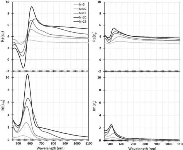
z”() are first determined using the optical properties of thefitted Au loaded polymer layers (NC) and the PS layer, through Equations 4 and 5. The resulting effective optical properties are shown in Figure 8.
Figure 8. Real (upper plots) and imaginary (lower plots) parts of the components
// (left)and
z (right) of the lamellar nanoplasmonic thin films, as computer using Equations 4 and5 from the Model 1 SE extractions for different values of N between 5 and 25 (MG-extracted
f
between 7 and 31%,). The resonance amplitude varies as N increases, due to the increasing volume fraction of introduced plasmonic nanoparticles.The analysis of the SE data through direct inversion as a uniaxial effective medium (Model 2) leads to a similar or better goodness-of-fit, compared to Model 1. Figure 9 shows the comparison between the components
//’() extracted for N = 15, N = 20 and N = 25 using Models 1 and 2. Models 1 and 215
although z shows a little more variation between the models. The agreement between the extractions
of the two models substantiates the main result of this experimental study showing that the dielectric functions
// and
z have opposite signs in a finite wavelength range.Figure 9. Comparison between the real part of the ordinary components in the cases of
the multilayer (Model 1, continuous lines) and uniaxial model (Model 2, dashed lines) for N=15 (a), N=20 (b) and N=25 (c).
As is shown on the Figure 8, the dielectric functions
// and
z both present a resonance at thewavelength =580 nm (or alternatively a photon energy of 2.1 eV), close to the plasmon resonance of the gold nanoparticles. However, the resonance amplitudes of the two components significantly differ. In the case of
z, this amplitude is limited and varies only little with the value of N, in direct relationwith the amount of gold nanoparticles in the nanostructure. By contrast, the resonance of
// is strongerand its amplitude significantly increases with N, reaching a regime of negative values beyond N=20. As a result, strong artificial anisotropies with different characteristics are found across the spectrum. Finally note that attempting to combine the top Au deposit layer (of thickness dSAu) into the effective
uniaxial medium smears its properties and does not produce negative
//, in contrast with the analysesbased on the two used models. Therefore, future studies will aim at lifting off the uncontrolled detrimental gold deposit top layer. In the current analysis, it is regarded as an experimental artifact whose analysis needs to be isolated from the analysis of the targeted nanostructure below it.
C/ Hyperbolic dispersion relation
We consider three regions of strong anisotropy denoted A:
z’ >
//’ > 0 ( = 481 nm), B:
//’ < 0 <
z’( = 539 nm) and C:
//’ >
z’ > 0 ( = 670 nm) indicated on Figure 10, which displays the values of
//and
z for N = 25 (corresponding to a MG-extractedf
= 31%). The iso-frequency dispersion diagrams16
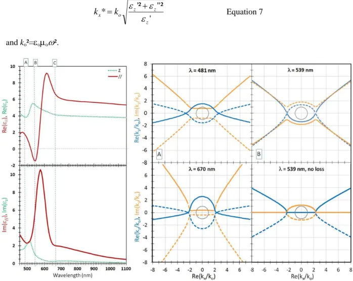
shown on Figure 10. For each frequency ω considered (or equivalently, excitation wavelength), two wavevector ranges can be distinguished kx < kx* and kx > kx*, with
'
"²
'²
*
z z z o xk
k
Equation 7 and ko²=
o
o
².Figure 10. Left: Parallel (red continuous line) and perpendicular (green dotted line)
components of the uniaxial dielectric function of the lamellar nanoplasmonic stack for N = 25 (fAu ~ 30% in the NC layers). The vertical blue dashed lines indicate the three
conditions (A: = 481 nm; B: = 539 nm; C: = 670 nm) chosen for the calculation of the dispersion relations, which are displayed in the right part. Right: Dispersion relation at ky = 0,
showing the real (blue lines) and imaginary (orange lines) parts of the kz component of the
wave-vectors in the material as a function of the kx component. Thick continuous and dashed
lines correspond to opposite solutions of Equation 3. The thin black continuous circle corresponds to the wavevectors propagating in air
k
x2
k
z2
k
o2, shown for reference. The plot labeled D, shown for reference, is a fictional hyperbolic case without losses: at = 539 nm,
//’ and
z’ are set to the values for case B, whereas
//” and
z” are set to zero.
Cases A and C present typical elliptical dispersion diagrams, when both
//’ and
z’ are positive: onecan observe, for small values of kx (kx < kx*), two symmetrical elliptical branches where the real part
of kz is significantly larger than the imaginary part, typical of an attenuated propagation. For larger kx
17
and which are characterized by a predominantly evanescent behavior (imaginary part of kz much larger
than the real part). In the case B when
//’ < 0 <
z’, we find that the dispersion diagram presenthyperbolic branches for kx > kx*, as well as elliptical curves at small kx.
These diagrams are related to the strong optical anisotropy of the lamellar stack, obtained as a consequence of the resonant nature of the NC layers. The significant losses (Re(kz) ≈ Im(kz))
associated with the hyperbolic propagation are another consequence of this resonant nature.
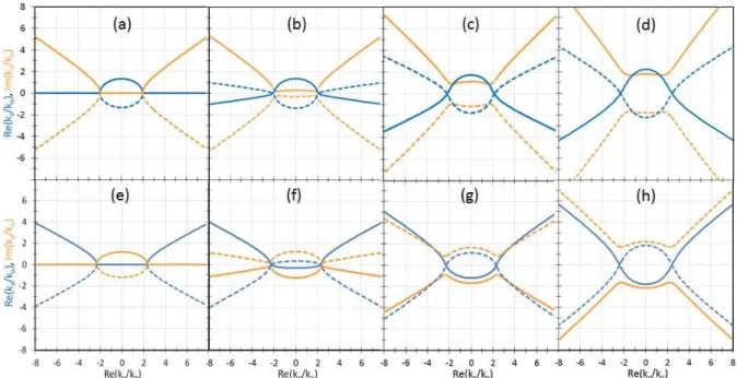
To understand the significance of these dispersion curves, it is useful to recall the usual description of elliptical and hyperbolic media. The ideal cases are displayed in the Figures 11.a and 11.d, where two fictitious materials are considered with the real parts of the permittivity tensor set to the experimentally determined values in cases C (
//’ = 1.77,
z’ = 3.85) and B (
//’ = -1.42,
z’ = 5.42);and with imaginary parts set to zero: //” = z” = 0 (lossless materials). We represent the dispersion
relation (Equation 3) in the ky = 0 plane. In the elliptical ideal case (Fig. 11.a), the propagative modes
(Re(kz) ≠ 0) are restricted to small wavenumbers (kx < kx*), while all possible large-kx modes are
forbidden63 and only purely evanescent (Re(kz) = 0). In the hyperbolic ideal case (Fig. 11.d), we
observe the opposite situation, with forbidden, purely evanescent modes (Re(kz) = 0) for small kx and
purely propagative modes (Re(kz) ≠ 0, Im(kz) = 0) for large kx, the latter potentially providing the
super-resolution property. The hyperbolic branches for kx > kx* present the shape of a one-fold
hyperboloid, with a forbidden gap in kx, as expected for a “metallic” 64
or type II4 hyperbolic medium, when the permittivity tensor
has two negative and one positive components.To depart from these idealized situations, let us now introduce a small amount of losses in the materials, see Figure 11.b and 11.e (here we arbitrarily took
//” = 4
z” = 0.8): the dispersion curvesbecome hybrid rather than purely elliptical or hyperbolic and present finite Re(kz) and Im(kz) at all
values of kx, allowing previously forbidden modes to propagate weakly. Purely evanescent waves for
the hyperbolic medium at small kx and the elliptical medium at large kx become weakly propagative
with Re(kz) ≠ 0 and Im(kz) >> Re(kz). The large-kx branches of the hyperbolic medium (Fig. 11.f)
present the same one-fold hyperboloid shape as that of the no-loss case (Fig. 11.e). Interestingly, when the imaginary parts
//” and
z” are further increased to simulate more losses (Fig. 11.(c-d) and(g-h)), the modification of the propagative and evanescent modes continues to occur, so much so that over most of the whole kx range, more or less strongly attenuated, propagative modes are observable.
In particular, we note that the intermediate hyperbolic cases (as represented in Figure 11.f and 11.g) still present predominantly propagative modes at large kx, which can support super-resolution
18
Figure 11. Dispersion relations at ky = 0, showing the real (blue line) and imaginary (orange line) parts of the kz component of the wave-vectors in the material as a function
of the kx component. Continuous and dashed lines correspond to opposite solutions of
Equation 3. The plots (a)-(d) (resp. (e)-(h)) correspond to fictional elliptical (resp. hyperbolic) cases with //’ and z’ set to the values for case C (resp. B), and //” =4 z” = 0
(a) and (e); //” =4 z” = 0.8 (b) and (f); //” =4 z” = 4 (c) and (g); and //” =4 z” = 8 (d)
and (h).
Finally, these results demonstrate the capacity of our bottom-up self-assembled multilamellar stack to respond as a hyperbolic effective medium in a given region of the visible spectrum (520 < < 560 nm). In the hyperbolic region, the dispersion relation allows propagative modes for large values of kx,
potentially providing super-resolution. These hyperbolic modes are however significantly attenuated due to the lossy nature of the media, in which the hyperbolic property is obtained from the resonant nature of the permittivity. These detrimental losses need now to be minimized by tuning the nature, size, size dispersity and organization of the nanoparticles. Furthermore, the same self-assembly methodology for lamellar stacks fabrication could be used with other nanoparticles with a resonance of better quality factor, or with a lamellar system including gain species (fluorophores or quantum dots) which could amplify the plasmons and compensate the losses.
In any case, we have demonstrated for the first time the possibility of using a self-assembly methodology for the fabrication of bulk hyperbolic material, which opens new fabrication routes for metamaterials aiming at super-resolution lenses.
19
ACKNOWLEDGMENTS
We thank I. Ly and C. Picard for help with the SEM imaging, and P. Barois, E. Garcia-Caurel, B. Gallas, and M. Stchakovsky for useful discussions and comments. This work was supported by the LabEx AMADEus (ANR-10-LABX-42) in the framework of IdEx Bordeaux (ANR-10-IDEX-03-02), France. It has benefited from an Aurora Hubert Curien Partnership, funded by the Norges Forskningsraad (NFR) and by the French ministères des Affaires étrangères et du Développement international (MAEDI) and de l’Education nationale l’Enseignement supérieur et de la Recherche (MENESR).
References
1
J.B. Pendry, D. Schurig, D. R. Smith, Controlling electromagnetic fields, Science 312 (2006) 1780–1782.
2
N. Engheta, Circuits with light at nanoscales: Optical nanocircuits inspired by metamaterials, Science 317 (2007) 1698-1702
3 B. Wang, K.-M. Huang, Shaping the radiation pattern with mu and epsilon-near-zero metamaterials, Progr.
Electromagn. Research. 106 (2010) 107-119
4 L. Ferrari, C. Wu, D. Lepage, X. Zhang, Z. Liu, Hyperbolic metamaterials and their applications, Progr. Quant.
Electr. 40 (2015) 1–40
5
Y. Guo, W. Newman, C. L. Cortes, Z. Jacob, Applications of Hyperbolic Metamaterial Substrates, Adv. OptoElectr. 452502 (2012) 2012
6 A. Poddubny, I. Iorsh, P. Belov, Y. Kivshar, Hyperbolic metamaterials, Nature Photon. 7 (2013) 958 7 A. A. Orlov, S. V. Zhukovsky, I. V. Iorsh, P. A. Belov, Controlling light with plasmonic multilayers,
Photonics Nanostruct. 12 (2014) 213-230
8 B. Wood, J. B. Pendry, and D. P. Tsai, Directed subwavelength imaging using a layered metal-dielectric
system, Phys. Rev. B 74 (2006) 115116
9
S. V. Shukovsky, O. Kidwai, J. E. Sipe, Physical nature of volume plasmon polaritons in hyperbolic metamaterials, Opt. Exp. 21 (2013) 14982-14987
10
J. Yao, Z. Liu, Y. Liu, Y. Wang, C. Sun, G. Bartal, A. M. Stacy, X. Zhang, Optical Negative Refraction in Bulk Metamaterials of Nanowires, Science 321 (2008) 930
11
X. Zhang, Z. Liu, Superlenses to overcome the diffraction limit, Nat. Mat. 7 (2008) 435-441
12
E. E. Narimanov, V.M. Shalaev, Beyond diffraction, Nature 447 (2007) 266-267
13 K. V. Sreekanth, M. ElKabbash, Y. Alapan, A. R. Rashed, U. A. Gurkan, G. Strangi, A multiband perfect
absorber based on hyperbolic metamaterials, Scientific Reports 6 (2016) 26272
14
H. N. S. Krishnamoorthy, Z. Jacob, E. Narimanov, I. Kretzschmar, V. M. Menon, Topological Transitions in Metamaterials, Science 336 (2012) 205-209
15
S. N. Kurilkina, M. A. Binhussain, V. N. Belyi, N. S. Kazak, Features of hyperbolic metamaterials with extremal optical characteristicsJ. Opt. 18 (2016) 085102
16
C. L. Cortes, W. Newman, S. Molesky, Z. Jacob, Quantum nanophotonics using hyperbolic metamaterials, J. Opt. (2012) 063001
17
Z. Jacob, J.-Y. Kim, G.V. Naik, A. Boltasseva, E.E. Narimanov, V.M. Shalaev, Engineering photonic density of states using metamaterials, Appl. Phys. B 100 (2010) 215–218
18
K. V. Sreekanth, K. H. Krishna, A. De Luca, G. Strangi, Large spontaneous emission rate enhancement in grating coupled hyperbolic metamaterials, Scientific Reports 4 (2014) 6340
19
Z. Jacob, I. I. Smolyaninov, E. E. Narimanov, Broadband Purcell effect: radiative decay engineering with metamaterials. Appl. Phys. Lett. 100 (2012) 181105.
20
20
D. Lu, J. J. Kan, E. E. Fullerton, Z. Liu, Enhancing spontaneous emission rates of molecules using nanopatterned multilayer hyperbolic metamaterials, Nature Nanotech. 9 (2014) 48-53
21
S.-A. Biehs, M. Tschikin, P. Ben-Abdallah, Hyperbolic Metamaterials as an Analog of a Blackbody in the Near Field, Phys. Rev. Lett. 109 (2012) 104301
22
Y. Guo, C. L. Cortes, S. Molesky, Z. Jacob, Broadband super-Planckian thermal emission from hyperbolic metamaterials, Appl. Phys. Lett. 101 (2012) 131106
23
A. V. Kabashin, P. Evans S. Pastkovsky, W. Hendren, G. A. Wurtz, R. Atkinson, R. Pollard, V. A. Podolskiy, A. V. Zayats, Plasmonic nanorod metamaterials for biosensing. Nat. Mater. 8 (2009) 867–871
24
K. V. Sreekanth, Y. Alapan, M. ElKabbash, E. Ilker, M. Hinczewski, U. A. Gurkan, A. De Luca and G. Strangi, Extreme sensitivity biosensing platform based on hyperbolic metamaterials, Nat. Materials 15 (2016) 621-627
25 U. Dürig, D. W. Pohl, F. Rohner, Near-field optical scanning microscopy, J. Appl. Phys. 59 (1986) 3318 26 T.A. Klar, S. Jakobs, M. Dyba, A. Egner, S. W. Hell, Fluorescence microscopy with diffraction resolution
barrier broken by stimulated emission, Proc. Nat. Acad. Sci. 97 (2000) 8206-8210
27
A. N. Boettiger, B. Bintu, J. R. Moffitt, S. Wang, B. J. Beliveau, G. Fudenberg, M. Imakaev, L. A. Mirny, C. Wu, X. Zhuang, Super-resolution imaging reveals distinct chromatin folding for different epigenetic states, Nature 529 (2016) 418–422
28 T. G. Mackay, Toward optical sensing with hyperbolic metamaterials, Opt. Eng. 54 (2015) 067102 29 J. B. Pendry, Negative Refraction Makes a Perfect Lens, Phys. Rev. Lett. 85 (2000) 3966
30
C. M. Soukoulis, M. Wegener, Past achievements and future challenges in the development of three-dimensional photonic metamaterials, Nat. Photonics 5 (2011) 523-530
31
T. Xu, A. Agrawal, M. Abashin, K. J. Chau, H. J. Lezec, All-angle negative refraction and active flat lensing of ultraviolet light, Nature 497 (2013) 470-474
32 A. Baron, A. Aradian, V. Ponsinet, P. Barois, Self-Assembled Optical Metamaterials, J. Opt. & Laser Techn.
82 (2016) 94-100
33 J. Gong, G. Li, Z. Tang, Self-Assembly of Noble Metal Nanocrystals: Fabrication, Optical Property, and
Application. Nano Today 7 (2012) 564–585
34 F. S. Bates, G. H. Fredrickson, Block Copolymers—Designer Soft Materials, Physics Today 52 (1999) 32-38 35
I.W. Hamley, The physics of block copolymers, Oxford Science Publications, 1998
36 F. S. Bates, G. H. Fredrickson, Block Copolymer Thermodynamics: Theory and Experiment, Annu. Rev.
Phys. Chem. 41 (1990) 525-557
37 Y. Fink, A. M. Urbas, M. G. Bawendi, J. D. Joannopoulos, E. L. Thomas, Block Copolymers as Photonic
Bandgap Materials, J. Lightwave Technol. 17 (1999) 1963-1969.
38 S. Salvatore, A. Demetriadou, S. Vignolini, S. S. Oh, S. Wuestner, N. A. Yufa, M. Stefik, U. Wiesner, J. J.
Baumberg, O. Hess, U. Steiner, Tunable 3D Extended Self- Assembled Gold Metamaterials with Enhanced Light Transmission, Adv. Mater. 25 (2013) 2713–2716
39 V. Ponsinet, Nanopatterns Produced by Directed Self-Assembly in Block Copolymer Thin Films, in Polymer
Surfaces in Motion - Unconventional Patterning Methods, J. Rodríguez-Hernández, C. Drummond, Eds., Springer International Publishing, 2015
40 M. Lazzari, C. De Rosa, Methods for the alignment and the large-scale ordering of block copolymer
morphologies, in Block copolymers in nanoscience; M. Lazzari, G. Liu, S. Lecommandoux, Eds, Wiley-VCH, Weinheim, 2006
41 J. G. Kennemur, L. Yao, F. S. Bates, M. A. Hillmyer, Sub-5 nm domains in ordered
poly(cyclo-hexylethylene)-block-poly(methyl methacrylate) block polymers for lithography, Macromolecules 47 (2014) 1411–1418
42 C. Tang, S. Hur, B. C. Stahl, K. Sivanandan, M. Dimitriou, E. Pressly, G. H. Fredrickson, E. J. Kramer, C. J.
Hawker, Thin film morphology of block copolymer blends with tunable supramolecular interactions for lithographic applications, Macromolecules 43 (2010) 2880–2889
43
M. Park, C. Harrison, P. M. Chaikin, R. A. Register, D. H. Adamson, Block copolymer lithography: Periodic arrays of similar to 1011 holes in 1 square centimeter, Science 276 (1997) 1401-1404.
44 M. M. Alam, Y.-R. Lee, J.-Y. Kim, W.-G. Jung, Variety of nanopatterns on different substrates using
21
45
J. Vieaud, O. Merchiers, M. Rajaoarivelo, M. Warenghem, Y. Borensztein, V. Ponsinet, A. Aradian, Effective Medium Description of Plasmonic Couplings in Disordered Polymer and Gold Nanoparticle Composites, Thin Solid Films 603 (2016) 452-464
46 B. Maxit, D. Bendejacq, V. Ponsinet, Facile formulation of high density well-ordered nanoparticle–copolymer
nanocomposites, Soft Matter 8 (2012) 1317-1320
47
J. J. Chiu, B. J. Kim, E. J. Kramer, D. J. Pine, Control of Nanoparticle Location in Block Copolymers, J. Am. Chem. Soc. 127 (2005) 5036-5037
48
C. Mendoza, T. Pietsch, J. S. Gutmann, D. Jehnichen, N. Gindy, A. Fahmi, Block Copolymers with Gold Nanoparticles: Correlation between Structural Characteristics and Mechanical Properties, Macromolecules 42 (2009) 1203–1211.
49
S.-H. Yun, S. M. Yoo, B.-H. Sohn, J. C. Jung, W.-C. Zin, S.-Y. Kwak, T. S. Lee, Electrically Anisotropic Thin Films Consisting of Polymeric and Metallic Nanolayers from Self-Assembled Lamellae of Diblock Copolymers, Langmuir 21 (2005) 3625–3628
50
B. H. Sohn, B. H. Seo, Fabrication of the multilayered nanostructure of alternating polymers and gold nanoparticles with thin films of self-assembling diblock copolymers, Chem. Mater. 13 (2001) 1752
51 These two additional layers are classically found in BCP thin films simply due to the local conservation of the
copolymer composition.
52
While tuning the film thickness to reach the flat surface cases, it is possible that we obtained in fact a film with a thickness not exactly equal to n do or (n+1/2)do. The layered structure of the copolymer then forces the film to
present regions of different thicknesses, with different regions satisfying one of the commensurability conditions and the film is therefore terraced, with a quantized surface topography: the step height of the terraces is do, so
that the free surface exposes the same block domain on each terrace.
53 P. F. Green, Wetting and dynamics of structured liquid films, J. Polym. Sci. B: Polym. Phys. 2003, 41, 2219 54
M. Maaloum, D. Chatenay, G. Coulon, Y. Gallot, Edge profile of relief 2D domains at the free surface of smectic copolymer thin films, Phys. Rev. Lett. 68 (1992) 1575
55 O. Hunderi, K. Johannessen, Effective-medium description of superlattices and the effect on non-locality,
Superlatt. Microstruct. 3 (1987) 193-198
56 X.-B. Kang, W. Tan, Z.-G. Wang, Validity of effective medium theory for metal-dielectric lamellar gratings,
Opt. Commun. 284 (2011) 4237–4242
57 P. A. Belov, Y. Hao, Subwavelength imaging at optical frequencies using a transmission device formed by a
periodic layered metal-dielectric structure operating in the canalization regime, Phys. Rev. B 73 (2006) 113110
58 E. Centeno, A. Moreau, Effective properties of superstructured hyperbolic metamaterials: How to beat the
diffraction limit at large focal distance, Physical Review B 92 (2015) 045404
59 A. Baron, A. Iazzolino, K. Ehrhardt, J.-B. Salmon, A. Aradian, V. Kravets, A. N. Grigorenko, J. Leng, A. Le
Beulze, M. Tréguer-Delapierre, M. A. Duarte, P. Barois, Bulk optical metamaterials assembled via microfluidic evaporation, Opt. Mater. Express 3 (2013) 1792–1797
60
S. M. Rytov, Electromagnetic Properties of a Finely Stratified Medium Soviet Phys. JETP 2 (1956) 466–475
61
J. C. M. Garnett, Colours in metal glasses and in metallic films, Phil. Trans. R. Soc. A 203 (1904) 385–420
62 P. B. Johnson, R. W. Christy, Optical Constants of the Noble Metals, Physical Review B 6 (1972) 4370–4379 63 T. Repän, A. V. Lavrinenko, S. V. Zhukovsky, Dark-field hyperlens: Super-resolution imaging of weakly
scattering objects, Optics Exp. 23 (2015) 25350-25364
64 S. Ishii, A. V. Kildishev, E. Narimanov, V. M. Shalaev, V. P. Drachev, Sub-wavelength interference pattern