Publisher’s version / Version de l'éditeur:
Canadian Journal of Civil Engineering, 8, 1, pp. 44-50, 1981-03
READ THESE TERMS AND CONDITIONS CAREFULLY BEFORE USING THIS WEBSITE. https://nrc-publications.canada.ca/eng/copyright
Vous avez des questions? Nous pouvons vous aider. Pour communiquer directement avec un auteur, consultez la première page de la revue dans laquelle son article a été publié afin de trouver ses coordonnées. Si vous n’arrivez pas à les repérer, communiquez avec nous à [email protected].
Questions? Contact the NRC Publications Archive team at
[email protected]. If you wish to email the authors directly, please see the first page of the publication for their contact information.
NRC Publications Archive
Archives des publications du CNRC
This publication could be one of several versions: author’s original, accepted manuscript or the publisher’s version. / La version de cette publication peut être l’une des suivantes : la version prépublication de l’auteur, la version acceptée du manuscrit ou la version de l’éditeur.
Access and use of this website and the material on it are subject to the Terms and Conditions set forth at
Limit states design : what do we really want?
Allen, D. E.
https://publications-cnrc.canada.ca/fra/droits
L’accès à ce site Web et l’utilisation de son contenu sont assujettis aux conditions présentées dans le site LISEZ CES CONDITIONS ATTENTIVEMENT AVANT D’UTILISER CE SITE WEB.
NRC Publications Record / Notice d'Archives des publications de CNRC:
https://nrc-publications.canada.ca/eng/view/object/?id=8d6cbc28-731c-4b50-86c9-2e2c440cc6d6 https://publications-cnrc.canada.ca/fra/voir/objet/?id=8d6cbc28-731c-4b50-86c9-2e2c440cc6d6, Council Canada de recherches Canada
.
LIMIT STATES DESIGN: WHAT DO WE REALLY WANT?
by D. E. Allen
Reprinted from
Canadian Journal of Civil Engineering Vol. 8, No. 1 , March 1981
p. 44-50
ANALYZED
DBR Paper No. 959
Division of Building Research
44
Limit states design: What
do we really want?
D. E. ALLEN
Building Structures Section, Division of Building Research, National Research Council of Canada, Ottawa, Ont., Canada K I A OR6
Received August 1 1, 1980
Revised manuscript accepted November 4, 1980
The purpose of the paper is to open discussion on the development of Canadian structural codes and standards. It argues for a common simple limit states format for all civil engineering structures, with the loading function contained in structural
-
use codes the same for all construction materials, and the resistance function contained in materials design standards the same for all structural uses. The format for loading and resistance functions and the degree of code complexity are discussed.L'auteur veut, par cet article, susciter des tchanges de nature a favoriser le progres des reglements et normes touchant le calcul des structures au Canada. I1 preconise, a cet Cgard, la mise au point et l'usage d'une version simplifiee et unique, fondee sur le principe des etats limites, applicable
a
toutes les structures du genie civil et comportant, d'une part, une seule definition des sollicitations (la fonction sollicitation) peu importent les materiaux mis en aeuvre, et d'autre part, une seule definition de la resistance (la fonction resistance) valable pour toutes les applications structurales. La forme des fonctions sollicitation et rksistance et le degre de complexit6 des reglements font I'objet d'une discussion.[Traduit par la revue] Can. J . Civ. Eng. 8. 44-50 (1981)
Introduction local stresses (determined by elastic structural analysis) Yudcovitch (1978) has pointed out that more precise reaching some form of material failure such as yield, structural design methods decrease the total cost of a crushing strength, or onset of permanent deformation. building project by no more than about 1% (the corre- Elastic structural analysis has a practical advantage sponding figure for "pure" structures such as bridges since only one theory is needed for all design calcula- and towers is about 5%). He therefore urged that "more tions. Working stress design, however, runs into diffi- investigation and discussion with practising engineers culty when the fundamental structural requirements of be undertaken prior to any such basic modification to strength and serviceability (limit states) are examined the code. " In Great Britain (Concrete 1979) many prac- more closely.
tising engineers accept limit states design principles but The first difficulty is that localized material failure feel that the refinements embodied in the recent British frequently does not represent failure of the structure. concrete code (British Standards Institution 1972) One example is the lateral stability of masonry walls. require more than ever the use of tables and packaged The current masonry code (Canadian Standards Asso- computer programs to arrive at simple answers. As ciation (CSA) 1977) allows 0.25 MPa tensile stress for practising engineers are the people most affected by lateral loads, about one tenth of the allowable compres- changes in structural codes and standards, they should sive stress. A masonry wall subjected to many years of . have a major influence on the format and style of weathering and differential movement may not have these documents. This paper, therefore, opens the any tensile strength at all in the mortar joints. An allow-
-
discussion Yudcovitch suggested by pointing out the able tension of 0.25 MPa, therefore, appears to be a need to replace working stress design by a common, fictional value whose purpose is to keep the force resul- a simple, limit states format for all civil engineering tant sufficiently far from the edge of the wall to prevent-
structures. Discussion on the definition of this format is It is derived from an earlier rule of zero needed before more limit states design standards are tension, which keeps the force resultant within the introduced. middle third of the wall. The trouble with this approach is that it gives no indication of the lateral stability or Working stress design safety factor of the wall against wind collapse. Another Working stress design once provided a unified example is the allowable concrete tensile stress in the approach to the design of all civil engineering struc- current rules for prestressed concrete. What is it for? tures, with a simple, common format that was easy to Not for strength, since this must be checked by an remember. It has been a practical tool for engineers. Is ultimate strength calculation. Is it for crack control? If it really necessary to replace this by something else? so, why is prestressed concrete treated differently fromThe method of working stress design is based on reinforced concrete? 0315-1468/81/010044-07$01 .OO/O
The second difficulty is that working stress design does not, in any consistent way, consider constraint stresses which occur as a result of manufacturing or construction processes (e.g., residual stress, prestress, and clamping forces in bolted connections), shrinkage, differential settlement, and temperature variation. Should they be included in the calculations or not? As a general rule they are omitted because they do not affect the strength of normal ductile structures. In fact,
-
if stress concentration is included in addition to other constraint forces, then the more accurate is the stress analysis the more unrealistic and uneconomical is the structure. If the structure fails in a brittle manner, however, they should be included. If cracking or permanent deformation is a potential problem, they also should be included. Working stress theory gives no guidance on this question.The difficulty with constraint stress also applies to stress redistribution. Sometimes failure stress (elastic stress at initial material failure) underestimates the strength of the structure. One example is the com- pressive strength of reinforced concrete where the yield strength of the reinforcing is added (incorrectly according to elastic stress analysis) to the compressive strength of the concrete. Another example is the post- buckling capacity of stiffened metal compression elements. Stress redistribution finally allows greater possibilities in design, for example by reducing con- gestion of reinforcing steel, or by the use of simple plastic theory. For continuous slabs and beams the latter is simpler and more realistic than elastic theory.
Finally, the safety factor is applied to the stress, a procedure which can occasionally be misleading. For the serviceability limit states, where the safety factor is essentially 1.0, it works quite well. For the ultimate limit states, where the stresses due to applied loads are additive, it also works quite well, although some economy could be gained by reducing the safety factor
.
on dead load. The stress safety factor runs into trouble,however, where there are counteracting loads or con-
*
straint stresses. If the dead load stress is opposite to the wind stress, the safety factor is applied to a small differ- ence between two large numbers, with the result that a
-
small increase in wind load will cause failure. The probability of failure therefore becomes quite high as the wind stress approaches the dead load stress (Fig. I), and this was a significant factor in the collapse of the Fenybridge Cooling Towers (Allen 1969). Similarly, if prestress opposes applied load stress, a small increase in load will cause a considerable change in stress, whereas if prestress is in the same direction and large in comparison with the load stress a large increase in load will cause only a small increase in stress. To get consis- tent safety, therefore, the safety factors on stress should
I vary as a function of the algebraic ratio of prestress to
I I 1 - F E R R Y B R I D G E C O O L I N G
-
- - - --
L I M I T S T A T E S 0 0 5 1 2 5 W I N D T E N S I O N I D E A D L O A D C O M P R E S S I O N RG. 1. Probability of failure for counteracting load effects.load stress (Tochacek and Amrhein 1971).
Working stress design has been modified to over- come many of these shortcomings. For example, work- ing stress formulae are generally based on member strength rather than material failure, e.g., those for steel in bending, reinforced concrete in compression or shear, and interaction formulae for combined axial load and bending. Quite often allowable stresses are not related to local (e.g., extreme fibre) stress but are member strengths expressed in terms of force divided by area, as for buckling, connectors, and truss compo- nents. For composite steel and concrete structures, the constraint stresses arising during construction are ignored. Rules have been introduced to give more con- sistency when considering counteracting loads and overturning. An adjustment in allowable stress could be made to gain economy for structures carrying mainly dead load. In fact, working stress design has been made equivalent to ultimate strength design (Schmidt 197?) by a number of such adjustments. Qualifications and adjustments of this kind, however, blunt working stress as a practical tool for design. Such a deficiency would not be particularly serious except for the changes that have taken place in civil engineering structural practice.
Changes in practice
Structures, particularly building structures, are be- coming lighter and thinner, with less effective damp- ing. This has arisen for a number of reasons-higher
46 CAN. I. CIV. ENG. VOL. 8, 1981
strength materials combined with reduced safety fac- tors, composite action, and less contribution towards stiffness and damping from non-structural components. The result is that serviceability is becoming more critical in design, and the limit states of deflection, vibration, and cracking are becoming as important as strength. Sometimes stress is a useful tool for this (e.g., for crack control or yield), sometimes it is not (e.g., for deflection and vibration). Even for crack control its application is limited. Constraint stresses often make it difficult to control cracking and it might be much more effective to provide an impermeable membrane against leakage and to design the structure for strength. Also, corrosion might be better controlled by detailing rein- forcement and cover than by restricting tensile stresses due to applied loads.
Fire resistance and structural integrity to contain local damage due to accidental loads are other limit state conditions not traditionally considered that may occasionally require design calculations. As very large deformations and constraint forces can arise under these "accidental" conditions, ultimate strength analysis rather than elastic stress analysis is appropriate.
Rehabilitation of existing structures is becoming much more common. For new structures under design, Yudcovitch (1978) has already pointed out that fur- ther refinement does not make that much difference in overall cost of a project. Rehabilitation costs, however, increase considerably if the existing structure is deemed to be unsafe. The problem has become particularly acute for bridges where truck loads have gradually increased over the years and, if realistic loads were used, a great number of existing bridges would be unsafe according to working stress design. For economic reasons, therefore, evaluation of exist- ing structures requires a closer description of strength and reliability than is provided by the working stress concept.
Structures are being used for a greater variety of purposes than before: for buildings of various kinds, for bridges, tanks, retaining walls and dams, pipes and sewers, towers and poles, falsework, nuclear contain- ment structures, and offshore platforms, to name the applications prevalent today. Thus there is a greater need to identify different limit states for different struc- tural uses and different environmental conditions. It is also necessary to ensure that design criteria previously derived for traditional construction apply to a wider number of applications in the future.
In addition to wider application to existing structures, there is a growing number of construction types to be considered. Composite structures are being introduced, e.g., wood and steel trusses, composite timber and con- crete decks, air-supported membranes, composite soil and steel culverts, and reinforced earth and stone retain-
ing structures. There are also various mixtures of pre- fabricated and cast-in-place types of construction. The tendency towards greater variety of construction types and the wider application of any given type means that a unifying design basis is needed as much as, or even more than, in the past.
Lack of a unifying basis is particularly evident in the
.
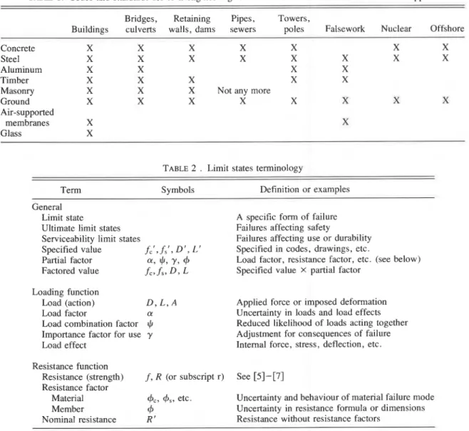
recent growth of codes and standards, which contain arather haphazard mixture of methods and criteria. In fact, the situation is beginning to get out of control. Table 1 shows the matrix of civil engineering codes and standards. Across the top are the use codes for build- ings, bridges, towers, etc., and down the side are the various materials involved in each of the use standards. As both uses and construction types as well as the experience and knowledge of each increase, the size of structural standards grows exponentially, particularly if each use code includes all criteria related to the behav- iour of various construction types. The new Ontario Bridge Code (Ontario Ministry of Transportation and Communications 1979), for example, is about 1200 pages thick, including commentaries. One way to con- trol this tendency is to organize all civil engineering structural codes and standards into material design stan- dards applicable to a wide variety of uses and use codes containing basic requirements for all construction materials. To do this requires a unifying basis with a common terminology and common format that separates the loading side of the design criteria (contained in the use codes) from the resistance side (contained in the material design standards).
Limit states design
Limit states design is intended to fulfil the need for a unifying basis in the same way that working stress design has done in the past. In addition, limit states design has the following advantages.
(1) It gives the designer a better understanding of the
.
fundamental structural requirements and of the behav- iour of the structure in meeting these requirements. This-
enables him to exercise better judgement in the design and evaluation of structures used for different purposes . and subjected to different environmental conditions.(2) It provides reliabilities more consistently related to the consequences of failure, and as a result, is more economical for cases which were previously overde- signed (e.g., structures under high dead load, structures such as bridge slabs whose strength was considerably underestimated by working stress design, and structures whose failure does not result in serious consequences), and better safety for those rare cases previously under- designed (e.g., components subject to counteract- ing loads). It therefore results in an overall material economy.
TABLE 1. Codes and standards for civil engineering structures. X means that a code or standard applies Bridges, Retaining Pipes, Towers,
Buildings culverts walls, dams sewers poles Falsework Nuclear Offshore
Concrete X X X X X X X
Steel X X X X X X X X
Aluminum X X X X
Timber X X X X X
Masonry X X X Not any more
Ground X X X X X X X X
Air-supported
membranes X X
Glass X
TABLE 2 . Limit states terminology
Term Symbols Definition or examples
General
Limit state A specific form of failure
Ultimate limit states Failures affecting safety
serviceability limit states Failures affecting use or durability Specified value f C 1 , f s ' , D ' , '5' Specified in codes, drawings, etc.
Partial factor ff, $, Y ,
4
Load factor, resistance factor, etc. (see below)Factored value f ~ , f ~ , D , L Specified value x partial factor Loading function
Load (action) D , L , A Applied force or imposed deformation
Load factor a Uncertainty in loads and load effects
Load combination factor $ Reduced likelihood of loads acting together Importance factor for use y Adjustment for consequences of failure
Load effect Internal force, stress, deflection, etc.
Resistance function
Resistance (strength) f , R (or subscript r) See [ 5 ] - [ 7 ]
Resistance factor
Material
4s,
etc. Uncertainty and hehaviour of material failure modeMember
4
Uncertainty in resistance formula or dimensionsNominal resistance R ' Resistance without resistance factors
(3) It has been adopted by the International Stan-
.
dards Organization as the basis for international model standards. This will be important for Canadian . engineers involved in projects outside Canada.In fact, limit states design has been gradually intro- duced over many years, first for concrete and more recently for steel, and is now being developed for other materials. The problem is to give it the definition it needs to make it a practical tool for the design of all civil engineering structures and also serve as a basis for harmonization of codes and standards. A CSA technical committee representing each of the codes and standards affected (originally a CSAmational Building Code joint committee) has been set up to do this, and a set of guidelines (CSA 198 1) drawn up containing basic prin- ciples, common terminology, and format. The common
terminology is given in Table 2; the basic format is as follows.
Ultimate limit states:
Serviceability limit states:
1
r - - - r n
[2] serviceability criterion 2
L--
effect of ~ervice loads The solid boxes (loads, load factors, and basic service- ability criteria) are generally contained in the use codes and the hatched boxes (resistances, performance fac- tors, and methods of analysis) are contained in the material design standards.48 CAN. J. CIV. EN( ;. VOL. 8, 1981
basically unchanged from that of existing standards, but the format for the ultimate limit states requires closer study, prticularly the loading and resistance functions. Format for loading
Traditionally, loads have been classified as dead
loads, D , which act permanently, and live loads, L ,
which are expected to vary during the life of the struc- ture. Loads that are not likely to occur, but which may have to be considered as significant in the design (vehicle impact, explosion, and fire), are called acci-
dental loads, A . The criteria for combining loads for
design calculations depend on the frequency and dura- tion of action of each of the loads.
The present load format for limit states design in the National Building Code of Canada (1980) and Ontario Bridge Code (Ontario Ministry of Transportation and Communications 1979) is
[3] factored loads = h i D i
+
+CcxjLjwhere the load combination factor,
+,
is equal to or lessthan 1.0, depending on how many live load items are being considered. The National Building Code con-
siders 4 load items, with about 6 or 7 significant combi-
nations. The Ontario Bridge Code considers 24 load items, with 17 load combination cases. For any particu- lar structure, however, the number of combinations requiring consideration is usually much smaller.
Another way of looking at load combinations is to combine the maximum lifetime value of the predom- inating live or accidental load with the frequent or sus- tained values of the other loads (Turkstra's principle):
[4] factored loads =
EqDi
+
a l L l+
CcxjLjtwhere L j t refers to a frequent or sustained value of the
load. One advantage of this approach is that it provides a principle for determining load combination rules that is useful to designers when considering situations not covered by codes. The frequent or sustained values of the loads may also be appropriate for serviceability
calculations, e
.
g .,
creep deflection. For practical codeapplications, [4] may be simplified to include only
those cases that are significant for a particular use. For example, Ellingwood et al. (1980) used this principle to derive a loading format for buildings in the United States.
The guidelines (CSA 1981) give a linear transforma-
tion with a load factor matrix, ai,, as a general rule' and
suggest [3] and [4] as a basis for simplification. A
or
accidental situations (e.g., fire, impact, or loss ofsupport) the load factors are reduced to 1.0. This results in
approximately the same overall risk of failure.
simple load combination rule seems to be appropriate for most structures (see section on code complexity), but Turkstra's principle, stated in words, would also guide the designers for nonstandard cases, e.g., indus- trial buildings. Should there be a common format for the loading function for different structural uses and, if so, which one is best?
Format for resistance
Working stress design has a very simple format for resistance, namely the stress corresponding to some form of material failure divided by the stress safety factor. The stress safety factor takes into account differ- ences in material failure modes, including differences in their variability, but not differences in the loads or peculiarities of load combinations.
When plastic design was introduced, the emphasis was changed to strength, and the safety factors were applied to the maximum expected loads and therefore called load factors. As the safety factors were applied to the loads they could take directly into account the differences in loads and peculiarities of load combi- nations, but could not differentiate between material failure modes. The disadvantage is that different sets of load factors would have to be specified in the materials standards for different material failure modes, and this is not a practical scheme. The steel code solved this problem by multiplying the allowable stresses given in the allowable stress section of the standard by the safety factor for yield, 1.7; this gives a good estimate of yield strength but not of buckling or of connection strength. Since it was decided that the concrete code would completely replace working stress design by ultimate strength design, it was necessary to introduce a resis- tance factor to take into account different failure modes. It is very much in the interest of design practice and the writing of codes, standards, and handbooks to separate the loading function from the resistance func- tion. Limit states design therefore defines load factors to take into account safety considerations not dependent
on material or type of construction, and resistance fac-
-
tors to take into account safety considerations not
dependent on loading or structural use. In Europe, and ,
for composite structures in the Canadian steel standard
-
(CSA 1974), the resistance factors are applied to the materials or connecting devices (material factors). But for concrete design in the United States and Canada (CSA 1973), the resistance factors are applied to the member strengths (member factors). The question
arises-should there be a common approach for dif-
ferent materials and types of construction and, if so, which method should be adopted?
For homogeneous structures (i. e., made of one mate- rial only) it does not matter, since the member resis-
where f is the material resistance, A is the area (or other geometric parameter such as section modulus), and
P
is a reduction factor for buckling (often equal to 1.0). For a composite structure made of two or more substantially-
different materials, however, there is a difference, since member resistance, R , is determined as follows: com-t pression and shear (parallel behaviour),
[61 R = P l A lfl
+
P2A2f2bending (weakest link behaviour) ,
where the subscript "conn" refers to a connecting device. Sometimes the strength of a connecting device or anchor itself is given by min (Alfi, A2f2).
A disadvantage of the member factor for composite structures is that it does not take into account the differ- ences in variability and behaviour of the different material failure modes within a structural member. An example of this is a concrete-filled steel pipe column whose strength is determined from [6]. If the pipe column is thick, short, and has a thin steel enclosure, then the strength is governed primarily by the concrete, and the member factor would have to correspond to that for concrete in compression. If the member is short and thin and a thick shell pipe is used, then the strength is largely determined by the yielding of the steel, and the member factor is consequently much higher. To get around this difficulty the member factor should vary as a function of the percentage of steel. It is not this sim- ple, however, because as the length of the column increases, the resistance to buckling of the concrete component decreases much more rapidly than does that of the steel component. The member factor should therefore vary as a function of slenderness as well as percentage of steel. If for simplicity a constant value is used for the member factor, then a penalty in material consumption occurs for members whose resistance is governed primarily by the steel component. Other examples where the same principle applies are shear, anchorage, and combined bending and compression in reinforced concrete structures, and the difference between friction and cohesion in soils.
This disadvantage does not occur with the use of the material factor because each material failure mode of the composite structure is assigned its appropriate resistance factor and there is no need for varying fac- tors. (Incidentally the material factor is one advantage of working stress design.) The reasoning is the same as for the separation of dead load and live load factors.
There are, however, safety considerations related to
member resistance though not to material failure mode, e.g., uncertainty in the member resistance formula, dimensional variations, and member importance. The guidelines (CSA 1981) have therefore introduced a member factor in addition to a material factor. For code simplicity the member resistance factor, generally around 0.9- 1 .O, might be incorporated into the resist- ance formula.
Because of the increasing use of composite structures containing different materials and connecting devices, it appears that such a common resistance format is desi- rable. The member factor has been used in concrete practice for many years, and it is therefore important that practitioners express their opinions on this question before code decisions are made.
Code complexity
A scientific understanding of structural behaviour and reliability is all very well, but to what extent should it be applied in practice? Yudcovitch (1978) provides one way of looking at the question, namely the econo- mic return for increased accuracy. This includes time spent by the designer in pondering unfamiliar formulae and making calculations (possibly alleviated by the computer, but even here there is "turn around time"). Economic considerations indicate that modelling preci- sion is not needed for designing new buildings, particu- larly small ones, but that more precision is needed for "pure" structures such as bridges and for key members, and particularly for evaluation of existing structures. Also, some structures are "one-off" and designed by one engineer without the aid of computers, handbooks, etc. (it would take too long), whereas others are mass-produced and therefore justify greater design precision. These considerations indicate a need for some flexibility.
Failure statistics also shed some light on this ques- tion. Available information (Hauser 1979) indicates that human error is the predominating influence in most failures, and that safety and serviceability risk levels are controlled and adjusted mainly through quality assur- ance procedures (checking, inspection, etc. to counter- act errors) rather than by adjusting the safety factors. This suggests that a simple design format with relative- ly few numerical safety factors is appropriate for most civil engineering structures. (More complicated formats can, in fact, lead to greater likelihood of human error.) Vastly different risk levels are required, however, for different structural uses, ranging from farm storage sheds at one end of the scale to nuclear containment structures at the other. In addition to the differences in quality assurance procedures required for different risk levels, therefore, there is also a need for some flexibil- ity in modelling precision.
- -
50 CAN. J. CIV. ENG. VOL. 8. 1981
the above that it should primarily be in the estimation of Conclusions
loads and resistances, not in the basic format and safety A simple limit states design format is suggested for
factors. One clause that provides flexibility is that for future structural codes and with resistance
axial load and bending in the concrete standard (CSA and loading in the form of principles and vary-
1973). It States the fundamental principles and leaves it ing degrees of precision given in appendices or other
to the designer to take it as far as he wants. He can use documents. To avoid safety factors whose values jump
handbooks and computer programs or he can easily 0, vary from one mode of failure to another, a material
.
recall a very simplified form of the principle. The latter factor is needed for resistance.
is particularly useful for preliminary design and check- %
ing. A clause written in the form of principles also Acknowledgment
eliminates the need for an explanation of its meaning in
This paper is a contribution from the Division of a commentary.
Building Research, National Research Council of If the resistance requirements are stated by a variety
of formulae in which the fundamental principles are not Canada, and is published with the approval of the
Director of the Division. self-evident, it is much more difficult to do this. For this
reason J f c l and
J F ~ ,
which appear in concrete and steelstandards, might well be replaced by parameters with ALLEN. D. E. 1969. Safety factors for stress reversal. Interna-
tional Association for Bridge and Structural Engineering,
clearer physical meanings. In shear and torsion for- Publication 29-11, p. 19.
for 'OnCrete structures~ for '!fC' might BRITISH STANDARDS INSTITUTION. 1972. The Structural use of
be the tensile strength of concrete, f t . In concrete. CP 1 10-1972. London, England, 353 p.
buckling formulae for steel structures, the idea of crit- CANADIAN STANDARDS ASSOCIATION. 1973. Code for the
ical slenderness, defined as the slenderness at which the design of concrete structures for buildings. CSA
elastic buckling strength is equal to the yield strength, A23.3-1973. Rexdale, Ont., 123 p.
might be introduced into the standard, i.e., 1974. Steel structures for buildings. CSA
S16.1-1974. Rexdale, Ont., 114 p.
F , = FE = k2E/(critical s~enderness)~ 1977. Masonry design and construction for buildings.
CSA S304-1977. Rexdale, Ont., 91 p.
or 1981. Guidelines for the development of limit states
critical slenderness = k (E /FY)lt2 design. CSA Special Publication S408- 1981. Rexdale, Ont.
CONCRETE. 1979. Letters to the Editor. 13(5), pp. 16- 18.
where the coefficient k takes into account the kind of ELLINGWOOD, B., GALAMBOS, T . V., MACGREGOR, J. G.,
buckling under consideration, e.g., column buckling and CORNELL, C. A . 1980. Development of a probability
(k = T), shear buckling, local buckling, and lateral- based load criterion for American National Standard A%.
torsional buckling, ~h~ buckling coefficient,
p
in [ 5 ] , is National Bureau of Standards Special Publication 577.then given directly in of the ratio of slenderness Department of Commerce, Washington, DC, June 1980,
222 p.
'lenderness (see the in the HAUSER, R. 1979. Lessons from European failures. Concrete
steel standard (CSA 1974)). Slenderness limitations, International, p, 21,
for for flanges in can be NATIONAL BUILDING CODE OF CANADA. 1980. Associate
expressed in terms of critical slenderness instead of as committee on the National Building Code. National
a constant divided by
JF,.
Expressions containing Jf,' Research Council of Canada, Ottawa, Ont., pp. 139- 140. ,and
J F ~
also suffer because they depend on the units ONTARIO MINISTRY OF TRANSPORTATION AND COMMUNI-chosen for fcl and F,. CATIONS. 1979. Ontario Highway Bridge Design Code.
One of the advantages of working stress design is that Toronto, Ont.
there are no factors to be considered (load, resistance, SCHMIDT, W. 197? (exact year of publication unknown).
and importance factors), i.e., the designer is sure that Ultimate strength design simplified-an equivalent stress '
method. W. Schmidt, Publisher, Chicago, IL.
they have already been included. One way to eliminate TOCHACEK, M , , and AMRHEIN, F, G. 1971. Which design
the factors is to include factored loads, i.e., ultimate for prestressed steel. American Institute for Steel
loads and service loads, in addition to specified loads, ~ ~ ~Engineering Journal, January 1971, p. 18. ~ t ~ ~ t i ~ ~
and factored material resistances in addition to specified YUDCOVITCH, H. 1978. The basic philosophy and recent
resistances, in structural codes and standards. Should development of safety margins: Discussion. Canadian
such a scheme be considered? Journal of Civil Engineering, 5(3), p. 138.