Design and Fabrication of a Piezoelectric Stack
Actuator for Use in a Needle-Free Jet Injector
by
Randall Miller Briggs
Submitted to the Department of Mechanical Engineering
in partial fulfillment of the requirements for the degree of
Master of Science in Mechanical Engineering
at the
MASSACHUSETTS INSTITUTE OF TECHNOLOGY
June
2018
@
Massachusetts Institute of Technology 2018.
A uthor ...
All rights reserved.
Signature redacted
Department of Mechanical Engineering
May 22, 2018
Signature redacted
Certified
by...
Hatsopoulos Professor of
Accepted by ...
Ian W. Hunter
Mechanical Engineering
Thesis Supervisor
Signature redacted
qkwRohan Abeyaratne
Chairman, Department Committee on Graduate Students
MASSACHUSETS INSITUTE OF TECHNOLOGY
JUN 2 5 2018
Design and Fabrication of a Piezoelectric Stack Actuator for
Use in a Needle-Free Jet Injector
by
Randall Miller Briggs
Submitted to the Department of Mechanical Engineering on May 22, 2018, in partial fulfillment of the
requirements for the degree of
Master of Science in Mechanical Engineering
Abstract
This thesis presents the design of a piezoelectric ceramic stack actuator for use with needle-free jet injection (NFJI) devices. While NFJI devices have been in use for over
60 years only recently have they been electronically actuated which allows for precise
control of jet velocity, penetration depth, and injection volume. Most NFJI devices have been designed for fluids with a similar viscosity to water. Here we design an actuator for use with high viscosity fluids and non-newtonian fluids. The piezoelectric stack actuator presented in this work has been designed to deliver injection volumes of up to 30 microliters while pressurizing the fluid to over 40 MPa in order to achieve the necessary fluid velocities for injection. We have further presented all the methods used in order to fabricate functional lead zirconate titanate (PZT) piezoelectric ceramic discs. These discs are the basic building blocks for assembling a full stack actuator for NFJI.
Thesis Supervisor: Ian W. Hunter
Acknowledgments
I would like to thank Prof. Hunter first of all. He has created a truly unique
environ-ment in the BioInstruenviron-mentation Laboratory where students can feel completely free and encouraged to explore subject areas outside of their normal domain of expertise. This atmosphere has really helped me to get out of the mentality of only being a mechanical engineer. Instead, I have learned to not narrowly define myself and to be willing to learn necessary information from a wide variety of fields in order to tackle the difficult problems in science and engineering.
I would also like to thank all of my lab members in the BioInstrumentation
Lab-oratory. They have provided essential guidance and many instances of advice and assistance with my work. My experience in the lab would have been quite empty without the help and friendship of all the awesome lab members.
I am so thankful to my parents for all their love and support over the years. I
would especially like to thank my dad for how much he did and how hard he worked so that I could be at MIT and graduate. He always cared about our education so much and did everything in his power to give us the best education in the world. There is no way that I would be at MIT without him. I lost my dad during the course of this thesis work and it has been a very trying time. I know that he would be proud to see me completing my Masters Degree. I love you, dad. I can't wait to see you again.
I would like to especially thank my dear wife, Johanna. She has stood by me
through some very difficult times in these past three years and she has been a constant source of support and comfort through all of the ups and downs of graduate life. Thank you, Johanna, for being willing to pass through this adventure together with me. You're really my best friend.
"But thanks be to God, who always leads us in triumph in the Christ and manifests the savor of the knowledge of Him through us in every place." -2 Corinthians 2:14
Contents
1 Introduction 13
1.1 The Purpose of this Thesis . . . . 13
1.2 B ackground . . . . 14
1.2.1 Past Work in Piezoelectric Actuators for NFJI . . . . 14
2 Design of the Piezoelectric Actuator 19 2.1 Introduction to Piezoelectric Actuator Theory . . . . 19
2.1.1 Piezoelectric Effect . . . . 19
2.1.2 Poling of Piezoelectric Ceramics . . . . 20
2.2 Design Parameters . . . . 24
2.2.1 NFJI for High-Viscosity, Non-Newtonian Fluid Injection . . . 24
2.2.2 Detailed Design Parameters . . . . 24
2.3 Choice of Piezoelectric Material . . . . 25
2.3.1 Important Properties of Piezoelectric Materials . . . . 25
2.4 Systematic Design of Piezoelectric Actuator . . . . 29
2.4.1 Setting Other Design Parameters . . . . 31
2.4.2 Calculation of Green Ceramic Dimensions . . . . 33
2.4.3 Stack Dimensions . . . . 35
2.4.4 Lost Volum e . . . . 36
2.4.5 Resonant Frequency . . . . 37
2.4.6 Electrical Properties . . . . 38
2.4.7 First Order Fluid Calculations . . . . 40
2.5 Results of Design Process . . . . 44
3 Fabrication of Piezoelectric Actuator 47 3.1 Overview of Steps . . . . 47
3.2 Details of Fabrication Process . . . . 48
3.2.1 PZT Powder . . . . 48
3.2.2 P ressing . . . . 49
3.2.3 Binder Burn Out . . . . 49
3.2.4 Sintering . . . . 51
3.2.5 Disc Slicing . . . . 52
3.2.6 Polishing . . . . 53
3.2.7 Poling . . . . 54
4 Experimental Analysis 59 4.1 Method of Testing Individual Discs . . . . 59
4.2 Results and Discussion . . . . 61
5 Conclusion 63 5.1 Future Work. . . . . 63
5.1.1 High-Pressure Membrane Design . . . . 63
5.1.2 High-Pressure Valve Design for Repeated Injections . . . . 64
5.1.3 Binary Stochastic System Identification . . . . 65
5.2 Summary of Conclusions . . . . 65
List of Figures
1-1 Microjet device used for nanoliter injections. The transducer is a piezo-electric crystal element. Figure reproduced from [1]. . . . . 15
1-2 Piezoelectric microjet with a resistive-capacitive circuit which controls the expansion of the piezo actuator. Figure reproduced from [2]. . . . 16 1-3 Mechanically amplified piezoelectric stack actuator in NFJI device.
Figure reproduced from [3]. . . . . 17
2-1 Normal and Inverse Piezoelectric Effect. Figure reproduced from [4]. . 20
2-2 Poling Process. Figure reproduced from
[4].
. . . .
21
2-3 Structure of PZT Crystal above and below the Curie temperature, Tc. Figure reproduced from [5]. . . . . 22 2-4 Rheology of HA. Figure reproduced from [6]. . . . . 25 2-5 Strain vs. Pressure for several piezoelectric materials available from
APC. Material parameters taken from [7]. . . . . 27 2-6 High voltage stack actuator. Figure reproduced from [8]. . . . . 30 2-7 Full stack actuator assembly for NFJI. . . . . 34
2-8 Butterworth Van Dyke (BVD) equivalent circuit model for piezoelectric ceram ics . . . . 39 2-9 Impedance Bode plot for Butterworth Van Dyke (BVD) equivalent
2-10 Diagram showing the structural loop of the piezo actuator jet injec-tor assembly. This diagram shows the equivalent stiffnesses of the structural members and the important deflections involved. The black arrows show the definition of positive values for AX1 and AX2. The
green arrows show the definition of positive forces in each spring
equiv-alent element in the structural loop. . . . . 42
2-11 Photo of a typical PZT stack actuator after assembly. Image repro-duced from [10]. . . . . 45
2-12 Diagram demonstrating the alternation of disc poling polarity and elec-trode voltage in a stack actuator. Figure reproduced from [9].
....
453-1 PZT Spray-Dried Powder. Image reproduced from [11]. . . . . 49
3-2 Stainless steel punch and die for pressing . . . . . 50
3-3 Weighing out PZT powder for pressing. . . . . 51
3-4 Green ceramic rods after pressing. . . . . 52
3-5 Temperature profile for binder burn out step in furnace. The time axis is purposely left blank since the total time can vary. The total time of the process in our case was 20 hours. Figure reproduced from [12]. . . 53
3-6 SEM image of ceramic after the BBO step. Image taken by Jason Wang. 54 3-7 Sintering Enclosure. . . . . 55
3-8 Sintered Rods. . . . . 56
3-9 SEM image of sintered PZT ceramic. . . . . 56
3-10 Tank with mineral oil for slicing PZT ceramic rod. The sintered dia-mond saw blade is seen on the right side. The PZT ceramic rod is held in place in a custom machined collet on the left. The holding tank is made of clear acrylic in order to be able to see the process. . . . . 57
3-12 Image of the temperature-controlled mineral oil bath used for poling. The white block is made of PTFE and contains the metal plates with the PZT discs in the middle. The high voltage wires with silicone insulation are seen coming from the top to each side. . . . . 58 4-1 Three PZT discs tested. . . . . 59
4-2 Experimental setup for testing disc expansion and contraction. . . . . 60 4-3 Expansion test results. . . . . 62 5-1 High-pressure felxure-based piston seal. . . . . 63 5-2 Displacement field results of flexure-based seal FEA analysis. . . . . . 64
Chapter 1
Introduction
1.1
The Purpose of this Thesis
Provide a Background of Past Work
It is important to understand the content of this thesis in the context of previous work. This thesis will give a brief overview of researchers who have employed actuators for needle-free jet injector (NFJI) devices made with piezoelectric ceramics.
Introduce Basic Piezoelectric Actuator Theory
In order to properly design a piezoelectric ceramic actuator for NFJI, it is crucial to understand key elements of piezoelectric actuator theory and material science. This thesis will provide a practical overview of how piezoelectric ceramics work, which material properties matter when designing a stack actuator for NFJI, and why certain attributes of piezoelectric ceramics make them an excellent choice for NFJI in certain applications.
Describe the Relevance of Various Design Parameters for the Actuator
While the majority of this thesis is meant to be a general guide to researchers who wish to make custom piezoelectric actuators for NFJI, this project was undertaken with a specific application of NFJI as the goal. In later sections, this thesis will
introduce the particular application of NFJI in more detail and will demonstrate how certain design parameters are constrained by the application.
Care will be taken to explain the physical meaning and implications of each design parameter so that the reader can set the design parameters themselves and use this work for many different types of applications.
Present a Systematic Method of Designing a Piezo Stack Actuator
Based upon the design parameters, this thesis will present a method for systematically designing a piezoelectric stack actuator. I will discuss the important trade-offs in-volved when designing a stack actuator and will describe in detail how to sequentially create the design and then improve the design based on the design parameters.
Provide Detailed Instruction for the Fabrication of a Custom Piezo Stack Actuator
This thesis will present detailed instructions for how to fabricate a custom piezoelec-tric ceramic actuator using lead zirconate titanate (PZT) powder. These instructions can be used both in a laboratory setting or, with some modification, can be scaled up in an industrial setting.
1.2
Background
1.2.1
Past Work in Piezoelectric Actuators for NFJI
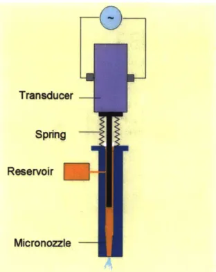
Arora et al [11 used a piezoelectric ceramic actuator to make a pulsed microjet that would deliver many rapid injections of extremely small volumes. They hypothesized that bruising and pain caused by traditional NFJI systems was due to the deep penetration depth of the jet. Because their device was designed to provide rapid small volume injections of 2 to 15 nL the penetration depth was limited to about 200 pL. The jet velocity of these small injections was still greater than 100 m/s. The piezoelectric ceramic actuator allowed them to deliver such small injections with a
relatively high velocity. Figure 1-1 shows a diagram of the device made by these
researchers.
Transducer
Spring
Reservoir
Micronozzle
Figure 1-1: Microjet device used for nanoliter injections. The transducer is a
piezo-electric crystal element. Figure reproduced from [1].
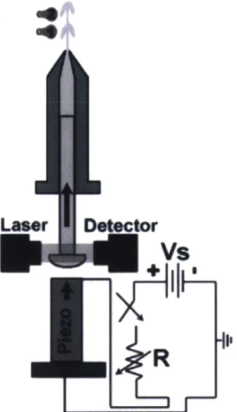
Stachowiak et al [2] used a piezoelectric ceramic actuator to control the jet velocity
of a NFJI device. By adjusting the resistance of the electric path to charge the piezo
actuator they were able to adjust the driving current and thus the driving velocity.
Figure 1-2 shows a diagram of their experimental setup. The variable resistance
circuit drives the piezo stack actuator from a fixed voltage source. The laser detector
monitors the movement of the piston in order to determine the fluid velocity of the
ejection.
Stachowiak et al
[3]
later demonstrated another NFJI device which used a
piezo-electric stack actuator along with a mechanical amplifier which increased the output
motion of the actuator. They were able to control the velocity of the jet in real time
in order to control penetration depth. This was achieved by controlling the amount
of time spend at a high velocity (for penetration) versus low velocity (for drug
deliv-Laser
Detector
+Vs
R
Figure 1-2: Piezoelectric microjet with a resistive-capacitive circuit which controls the expansion of the piezo actuator. Figure reproduced from [2].
ery). The typical ejection volumes during their experiments were 6 to 7 L. Figure 1-3 shows a diagram of this piezoelectric ceramic actuator along with the mechanical amplification stage.
In this thesis, we will demonstrate the design of a piezoelectric actuator for use in a NFJI device. This actuator is designed to provide both relatively large volume ejections (30 LL) and very high pressure in the fluid chamber (40 MPa). This device has been optimized for use with high viscosity and non-newtonian fluids which are difficult to eject with typical NFJI devices. Piezoelectric actuators are excellent for this purpose since they are able to pressurize the fluid chamber within microseconds and can quickly cause fluid flow with high pressure in order to induce shear thinning behavior.
Figure 1-3: Mechanically amplified piezoelectric stack actuator in NFJI device. Figure
reproduced from [3].
Chapter 2
Design of the Piezoelectric Actuator
2.1
Introduction to Piezoelectric Actuator Theory
In this section, I will describe the basic elements of piezoelectric theory that are important to understand when designing a piezo stack actuator for NFJI. There are many topics in piezoelectric material science that I will not cover since they are either irrelevant to this application or of second order importance.
2.1.1
Piezoelectric Effect
The most critical feature of a piezoelectric material for use as an actuator is the expansion or contraction of the material when an electric field is applied in the same direction as the poling direction of the material. The poling direction is the direction in which all the electric dipoles in the material are aligned. This expansion under an applied electric field is actually called the inverse piezoelectric effect. Figure 2-1 shows the difference between the inverse piezoelectric effect and the normal or forward piezoelectric effect.
The "generator action" or normal piezoelectric effect is that the material will produce a large voltage between the opposite faces of the material when a mechanical stress is applied in the poling direction of the material. If the mechanical stress is squeezing the material in the poling direction, the voltage produced will be in the
genermtr action motor action
(a) disk after (b) disk oomprnssed (a) disk sIrAtcked: (d) appled voltage (e) applied voltage
polwIzatow gemerated voltage generated voltage has same polarity hee polty
(poling) has same poaRity has polo*ly as poling vo~tag: opposite that of
as polfig voltage opposite *a of disk lengthens poling voltage:
poling voltage disk shortens
Figure 2-1: Normal and Inverse Piezoelectric Effect. Figure reproduced from [4].
same direction as the poling polarity. If the material is stretched parallel to the poling direction, this voltage will be in the opposite direction as the poling polarity. The poling polarity is shown in part (a) of Figure 2-1.
The "motor action" or inverse piezoelectric effect is that the material will expand or contract when an electric field is applied to the material. If the electric field is applied with the same polarity as the poling polarity, the material will expand in this direction (and shrink slightly in the perpendicular direction). If the electric field is applied with the opposite polarity of the poling polarity, the material will compress in this direction (and expand slightly in the perpendicular direction).
2.1.2
Poling of Piezoelectric Ceramics
We have mentioned that the poling polarity is determined by the direction of align-ment of the electric dipoles in the material. In this section we will describe how dipole alignment is achieved. Polarization or "poling" is the process of using an applied elec-tric field at high temperature to align the dipoles in a piezoelecelec-tric material.
Piezoelectric Ceramic Material Structure
All piezoelectric ceramics are made up of many small crystal domains that are
ran-domly oriented when the ceramic is first made. Within each of these individual crystal domains the crystal structure is uniform and thus the crystal domain has a single dipole polarity direction. Figure 2-2 part (a) shows this state of the ceramic
material. These crystal domains are then aligned by applying a large (2-3 MV/m) external electric field as seen in part (b) of Figure 2-2. Poling is done at an elevated temperature which increases the mobility of the individual crystal domains. This elevated temperature drastically increases the rate of polarization. Once the external electric field is removed and the ceramic cools the crystal domains remain largely oriented in the same direction. This final state of alignment is called the remnant polarization and can be seen in part (c) in Figure 2-2. The material will keep the majority of this remnant polarization essentially indefinitely, unless it is lost due to mechanical stress, high temperature exposure, or a high electric field in the opposite direction of the poling.
14) rsndgm orleniadn .E Polar 4b polwuma n in DC elaetrft 1d (a) I.umm pui-anrna.- ar-.
asdm
-*
ft pabdaom dmsb Ad mmw.dFigure 2-2: Poling Process. Figure reproduced from [4].
Curie Temperature
As mentioned previously, the poling process is performed at a high temperature in order to drastically speed up the process. The target temperature for this process is a few degrees Celsius lower than the Curie temperature for the particular piezo material. The Curie temperature is the temperature that marks the transition between two crystal structures of the material.
Above the Curie temperature, the crystal structure of the material loses its dipole moment. Without the dipole moment, the crystal domains cannot be oriented using an electric field. Below the Curie temperature, the crystal structure obtains an
asym-metry that produces the electric dipole moment. This is why it is crucial that poling
be performed at a temperature slightly lower than the Curie temperature. Figure 2-3
shows how the structure of lead zirconate titanate (PZT) crystal changes above and
below the Curie temperature.
*Pb
2
-@-
02-
Ti
4
+
Zr
4
Ak.6'1
F
F
h
W
W
IF
_i
V
T<Tc
Figure 2-3: Structure of PZT Crystal above and below the Curie temperature, Tc.
Figure reproduced from [5].
Causes of Depolarization
It is possible for a material to lose its polarization after the poling process has been
completed. It is important to be aware of the various conditions that can cause
the material to depolarize. Depolarization will reduce the effectiveness of the piezo
actuator and could render the actuator useless. Below is a partial list of the common
conditions that can lead to depolarization:
1. Thermal Depolarization
-
Heating a piezo ceramic material up to the Curie
temperature will certainly cause depolarization. It is recommended to operate
at a significantly lower temperature. The recommended upper operating
tem-perature is approximately half-way between 0 *C and the Curie temtem-perature of
the material [7, p. 23].
...F
....
(
M
P,
V..
...
..
... ... -AIM A is. -I
IML-i
T > Tc
2. Mechanical Depolarization - A very high mechanical stress applied to a piezo ceramic can disturb the orientation of the crystal domains and thus cause depolarization. The susceptibility to this phenomenon varies with different materials [7, p. 231.
3. Pyroelectric Depolarization - Even if the temperature of the material stays
below the upper recommended operating temperature, rapid temperature swings can still cause depolarization. This is because rapid temperature fluctuations can actually generate high voltages in piezo ceramics which cause electrical depolarization. The strength of this effect also varies with different materi-als [7, p. 23].
4. Electrical Depolarization - Applying a strong electric field in the opposite
direction of the poling polarity will cause depolorization in a piezo ceramic material. The degree of depolarization will depend on the exposure time, the temperature, the type of material, and other factors. In general any electric field in the range of 200 to 500 kV/m or greater applied in this direction will cause depolarization to some degree
[7,
p. 221.Asymmetric Actuation
Once a piezoelectric material has been polarized through the poling process, it can be actuated using an applied electric field. While a high electric field applied in the opposite direction of the poling polarity will cause depolarization, a high electric field applied in the same direction as the poling polarity will tend to reinforce the polarization of the material. Because of this effect, there is a significant asymmetry in the electric field that can be applied to the material. It follows that the material can be expanded much more than it can be contracted under an applied electric field. This feature will be important as we design our stack actuator.
2.2
Design Parameters
2.2.1
NFJI for High-Viscosity, Non-Newtonian Fluid Injection
This thesis is focused on designing a piezoelectric stack actuator that could be used to deliver small volumes (e.g. 10 to 30 pL) of fluid of variable viscosity to the upper dermis. A good example of such a high viscoity fluid is hyaluronic acid (HA) which also exhibits non-newtonian shear thinning behavior. We will use HA as an example high viscosity fluid to be delivered for this thesis. This specific application of the device gives us certain design parameters that we will use as a guide in designing the actuator.
2.2.2
Detailed Design Parameters
High Ejection Pressure
Hyaluronic acid (HA) is a non-newtonian fluid that can have a large range of dynamic viscosities at different shear rates. Figure 2-4 shows the typical relationship between shear rate and viscosity for HA
Based on experimental results within the BioInstrumentation lab, approximately 20 MPa has been found to be the required pressure to achieve a jet velocity which penetrates deep enough into porcine tissue. This required jet velocity is approximately
150 to 200 m/s.
Injection Volume
The required volume for each injection is approximately 10 pL. In order to be con-servative and protect against unexpected sources of lost injection volume, we will set this design parameter to be 30 1iL. This will allow us to deliver a full range of ejection
100.0--- HA solution - --Zero-shear viscosity 10.00 -0 1 .000 0.1000
-
I ,,,1 i , I , ,111 i ,0.1000
1.000
10.00
100.0
1000
shear rate (1
/s)
Figure 2-4: Rheology of HA. Figure reproduced from
[6].
2.3
Choice of Piezoelectric Material
2.3.1
Important Properties of Piezoelectric Materials
One critical value that we are interested in for our application is the maximum
pres-sure that can be exerted by a piezo actuator since this is directly related to the
ejection pressure. Surprisingly, this is determined by only three material properties:
d3 3 -
the piezoelectric charge constant in the poling direction,
E3 3 -the elastic
modu-lus of the material in the poling direction, and Emax
-
the maximum electric field that
the material can sustain before dielectric breakdown occurs. The maximum
achiev-able pressure is simply the product of these three parameters as seen in Equation 2.1
below:
Pmax= d33 -E33 -Emax .
(2.1)
This maximum pressure is achieved when the maximum electric field is applied
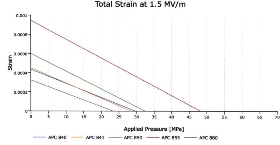
to a piece of piezoelectric material that is constrained from expanding. As the
piezo-electric piece is allowed to expand, the pressure drops linearly until the piezo piece
reaches its new equilibrium length. This effect is seen in Figure 2-5 for several dif-ferent piezoelectric materials. The maximum pressure that can be achieved by the piezoelectric element is also called the blocking pressure. In Figure 2-5 the blocking pressure is the intersection of the strain vs. pressure line with the horizontal axis.
Total Strain at 1.5 MV/m
I I I 5 2
0 5 10 15
20
APC 840
25 30 35 40 45 50 55 60 65 70
Applied Pressure
[MPa]
APC 841 APC 850 APC 855 - APC 880
Figure 2-5: Strain vs. Pressure for several piezoelectric materials available from APC. Material parameters taken from [7]. U) 0.001- 0.0008- 0.0006- 0.0004-
0.0002-The equation for the strain, c, of the piezoelectric material plotted in Figure 2-5 is
d3- Emax Papplied (2.2)
As can be seen from this equation, the piezoelectric charge constant, d33,
multi-plied by the maximum electric field, E3 3, sets the maximum strain for the piezo piece
under no load. As the piezo piece is compressed by the applied pressure, Papplied, it shrinks until finally reaching its original length when the strain equals zero at the horizontal axis.
The blocking pressure alone is not the only important parameter to look at when choosing a piezoelectric material. If the material has a very high stiffness, E33, and
a relatively low piezoelectric charge constant, d33, it is possible for the material to
have a high blocking pressure with a low maximum strain value. For the purpose of ejecting a fluid, this means that the actuator will be able to exert a very high pressure to the fluid chamber but will eject only a very small volume of fluid. In order to eject a larger volume of fluid in this case, it would be necessary to increase the length of the actuator considerably. This lengthening is needed so that the small value of maximum strain multiplied by the original length equals the required change in length, or stroke of the piston. This basic formula is
AL = e .Loriginai . (2.3)
The ejected volume, Vejected, is equal to the area of the piston, Apiston multiplied by the change in length of the actuator, AL, as
Veected = Apiston * AL. (2.4)
In order to choose a piezoelectric material for use with NFJI it is necessary to decide upon the minimum pressure at which the jet velocity is still sufficiently high for injection to take place. We have already determined that 20 MPa is necessary to achieve the desired ejection velocity, but since our fluid is non-Newtonian, the
pressure needed to maintain this jet velocity should decrease once the fluid starts to flow. Thus, we will somewhat arbitrarily set the minimum pressure for injection at 10 MPa. We will assume that the volume ejected is only useful if ejected above or equal to this minimum pressure. Any fluid that is ejected below this pressure is assumed to have a velocity too low to penetrate the tissue.
This new requirement of a minimum ejection pressure helps us to further refine our selection process. Our process has three key steps:
1. For every material, calculate the blocking pressure and the maximum strain.
2. Plot strain versus applied pressure.
3. At the minimum pressure needed for injection choose the material that has the
highest strain at this point. As long as this material also has a sufficiently high blocking pressure for the particular application, this is most likely the best choice.1
We can see from Figure 2-5 that APC material 855 has the highest strain at every pressure and in this case is the clear winner. All the materials on this plot are made
by APC and are different variants of lead zirconate titanate (PZT).
2.4
Systematic Design of Piezoelectric Actuator
Stack Actuator Design
This thesis is focused on the design of a piezoelectric stack actuator for use with NFJI. There are two primary types of piezoelectric stack actuators: high voltage stack actuators and low voltage stack actuators. High voltage stack actuators consist of individual piezoelectric ceramic discs which are stacked on top of each other with thin, metal electrodes in between each disc. Figure 2-6 shows the structure of a typical high voltage stack actuator. Low voltage stack actuators are made with a continuous, 'The reader should be aware that there could be a number of other important considerations when choosing a material such as maximum operating temperature, number of lifetime cycles, cost, manufacturability, density, brittleness, etc.
very thin strip of piezoelectric material on top of a very thin strip of metal. This tape is then folded back and forth on top of itself in order to form the stack actuator. High voltage stack actuators normally require about 1000 V to operate at full stroke. Low voltage stack actuators normally require about 100 V to operate at full stroke. In general, low voltage actuators have much higher capacitance than high voltage stack actuators and thus cannot normally be actuated as fast as high voltage stack actuators and require higher currents.
Top piece
Ceramic disks
-- -
Casing
Voltage Cable
Bottom piece
Figure 2-6: High voltage stack actuator. Figure reproduced from [8].
The primary reason we chose to fabricate a high voltage stack actuator is because of the relative ease of manufacturing individual piezoelectric ceramic discs rather than forming the thin tape necessary for a low voltage stack actuator. The relatively low capacitance of the high voltage stack actuator will also make it easier to provide the necessary driving currents in a small device.
2.4.1
Setting Other Design Parameters
We will now begin the design process by setting all the necessary parameters:
" Vij - The desired injection volume. We previously set this parameter to 30 LL.
" VfIisd - The total volume of fluid contained in the ejection chamber. This value will be important since the fluid itself will compress during ejection. The larger the volume of fluid in the ejection chamber, the lower the effective stiffness of the fluid becomes. We will set this to be 0.5 mL based on what is a reasonable fluid thickness (the thickness of the disc of fluid in the fluid ejection chamber). The fluid thickness in the fluid ejection chamber should be at least 10 times greater than the jet diameter so that the fluid dynamics are dominated by the high velocity jet and not by the viscous drag encountered by the fluid moving horizontally in the fluid ejection chamber.
" Gfluid - The bulk modulus of the fluid. It was difficult to find an accurate value
for HA so instead we used the average of the values for water and for glycerin. Water has a bulk modulus of 2.15 GPa and glycerin has a bulk modulus of 4.35 GPa. The average value which we used to represent the likely value of HA is 3.25 GPa. The bulk modulus will be used to calculate the ejection volume lost due to the compression of the fluid itself.
" d33 -The piezoelectric charge constant. This is the piezoelectric charge constant for APC material 855, which we chose for our application. For the 855 material this value is 630 x 10-12 m/V.
" E3 3 - The elastic modulus of the piezoelectric material in the direction of poling. For the 855 material this value is 5.1x 10¹⁰ Pa.
" Ea - The maximum electric field that can be withstood by the piezoelectric
material. For PZT, the maximum electric field the material can withstand before experiencing dielectric breakdown is around 2 MV/m. We will avoid this limit and instead set this value to 1.5 MV/m in order to leave a margin of safety.
" Pmin - The minimum pressure required to sustain injection velocity. We will only count the volume of fluid ejected above this pressure. We have set this minimum pressure to be 10 MPa
" Emax - The maximum electric field that will be applied to the piezoelectric material. It is important to remember that this electric field will only be applied to the piezoelectric material with the same polarity as the poling polarity. We have set this maximum electric field to be 1.5 MV/m.
" Vmax - The maximum voltage applied to the piezoelectric material. This value is largely determined by the driving electronics that we will use to control the voltage on the piezo stack actuator. The power electronics that we chose to drive the piezo stack actuator have a maximum voltage rating of 1200 V. We will plan on using 1000 V on our stack actuator in order to leave a margin of safety. As we mentioned earlier it is common for so called high voltage stack actuators to have a maximum applied voltage of about 1000 V.
" Dtck - The diameter of the stack actuator. This is the diameter of the discs that are used to make the stack actuator. It is not the outer diameter of the steel case that forms the outside of the stack actuator unit. Since we hope for this device to be hand-held in the future, we realized that this diameter could be no more than approximately 45 mm. This parameter causes many changes in later calculations as we will see shortly. In summary, increasing the stack diameter will increase the length of the stack actuator (in order to preserve ejected volume), will increase the time required for the stack to fully extend when a step increase in voltage is applied, and will increase the ejected volume lost due to the elongation of the outer steel case. This value had to be optimized by hand while balancing all of these trade-offs. We settled for a value of 30 mm. We will explain this process in more detail in the sections to follow.
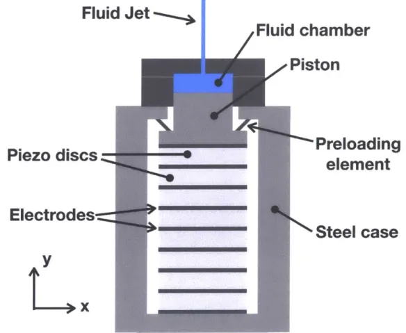
*Diston - The diameter of the piston driving the fluid. As seen in Figure 2-7 the
of the piezo stack itself since the preloading element will need to press down on the top of the stack below the piston head. We must make the piston slightly smaller in order to produce this surface for the preloading element to seat against. We will assume that a seating edge of 0.5 mm is sufficient based on the typical geometry of preloading elements such as Belville washers. So the piston diameter is 1 mm less than the stack diameter, or 29 mm.
" Apiston - The area of the piston head driving the fluid. This is simply based on the diameter of the piston. This area is 6.605x 10⁻⁴ M2.
" tfluid -The thickness of the disc of fluid in the ejection chamber. This value will be important for calculating the effective stiffness of the fluid in the structural loop. This value is simply the volume of the fluid divided by the area of the piston. It is equal to 0.757 mm.
2.4.2
Calculation of Green Ceramic Dimensions
The first practical calculation that we will need is the dimension of the "green" or unfired ceramic. The geometry of the stack actuator that we set as a parameter is describing the final, fired ceramic pieces. The ceramic will first be formed in larger dimensions and will shrink considerably in the process of firing.
We know from the literature (cite:APC blog) that the density of the pressed green ceramic will only be 60% of the density of the final ceramic pieces. This corresponds to an increase of density by a factor of 1.667:
Adensity
=1.667.
(2.5)If the density of the ceramic increases by this much, then the volume will decrease by a corresponding amount. Linear dimensions of the ceramic piece will change by a factor of the cube root of the change in volume. Alindim is the factor of change in
Fluid Jet
I
i JFluid
chamber
Piston
U
Preloading
Piezo discs
element
Electrodes--Steel case
tjx
1
Alindim = . (2.6)
density
The value of Alindim is equal to 0.843. Multiplying the reciprocal of this value by the stack diameter will give us the necessary diameter of the green ceramic,
1
Dgreen = x Dtack = 35.57 mm. (2.7)
Alindim
2.4.3
Stack Dimensions
In this section we will calculate the overall stack actuator dimensions based on the parameters set earlier.
We first calculate the stroke of the piston (occurring above the minimum pressure) that will be required to eject the desired fluid volume,
Strokepressure - V - 45.42 um. (2.8)
Next we will calculate the thickness of the piezoelectric ceramic discs, tdic. This is simply determined by the maximum electric field and the maximum voltage set earlier,
V.
t -se = * = 0.667 mm. (2.9)
Emax
We will set the thickness of electrode material, telectrode, to be 0.1 mm. This is an approximate estimate of the thickness of material that will allow for plenty of conductivity while remaining quite thin relative to the ceramic pieces.
When the minimum ejection pressure, Pmin, is applied to the piston, the pressure seen by the actuator will be slightly less since the diameter of the actuator is greater than that of the piston. The pressure seen by the actuator, Pstack, when 10 MPa is applied to the piston will be 9.34 MPa.
Next we will calculate the strain of the piezo actuator under the maximum electric field and with the minimum injection pressure applied to the piston,
Epiezo = d33 * Emax -Pt"" = 7.618 x
10-4
E33
We can now determine the necessary length of piezoelectric material, Lstack, needed in the stack actuator simply by dividing the stroke of the piston by the strain of the piezo material,
Lstack - Strokept"
--
59.62 mm.Epiezo (2.11)
Now that we know how much piezo material is needed, we can determine the integral number of piezo ceramic discs, ndiscs, that will be needed to achieve this length,
ndiscs = ceil( Lstack) 90 discs.
tdisc
(2.12)
So the true length of the piezo material in the stack is simply ndiscs multiplied by tdisc to give a value,
Lintstack = ndiscs * tdis = 60 mm. (2.13)
The length of the electrode material in the stack, Lelect,oda, will be,
Lelectrode =(ndiscs - 1) * telectrode= 8.9 mm . (2.14)
The full stack actuator length, Lfullstack is then,
Lfullstack = Lintstack + Lelectrode = 68.9 mm. (2.15)
2.4.4
Lost Volume
There are two primary sources of lost ejection volume:
1. Elongation of the steel case - When the actuator applies the ejection
pres-sure to the fluid the steel case elongates since it is part of the structural loop. (2.10)
This means that some of the stroke of the actuator is wasted on elongating the steel case rather than ejecting pressurized fluid. We assumed a basic hollow cylindrical shape for the steel casing. The length of the steel casing is slightly longer than the actuator itself. The wall thickness of the steel casing was as-signed to be 15 mm. The volume lost due to the elongation of the steel casing is calculated to be 0.733 tL.
2. Volumetric compression of the fluid - The fluid itself will compress since in reality it is not perfectly incompressible as is often assumed. At these high pressures the compression of the fluid cannot be ignored,
Viost - VGfuiad xP'" -1.538 UL. (2.16)
After accounting for the expected losses, the total volume that will be ejected is
27.73 [iL.
2.4.5
Resonant Frequency
it is important to calculate the resonant frequency of the stack actuator since this is related to the rise time of the actuator. The rise time is the time required for the stack to fully expand when a step voltage change is applied to the actuator.
The equation for the resonant frequency of a fixed end free end bar is,
7T x (2.17)
2LX rp
where L is the lenth of the bar, E is the elastic modulus of the bar, and p is the density of the bar.
Our stack actuator is made up of two materials: the piezoelectric ceramic discs and the metal electrodes in between them. We will assume that the metal electrodes are made of 6061 aluminum.
We will need to calculate the average density and the average elastic modulus of the stack in order to calculate the resonant frequency.
The average density of the bar will be,
_ Pelectrode Lelectrode + ppiezoLpiezo (2.18)
Lelectrode + Lpiezo
Assuming ppiezo = 7.6 x 10³ kg/rn3 (the value for PZT) and Pelectrode = 2.7 x
10' kg/m3 (the value for 6061 aluminum) the average density will be 6.97 x 10 kg/m3.
The equation for the equivalent elastic modulus is not so straightforward. We will skip the derivation of the equation and simply present it as,
E1E2(L1 + L2)
Eeuaeit =,(.9
E1L2 + E2L1
where the subscript 1 represents "piezo" and the subscript 2 represents "elec-trode". The equivalent elastic modulus is calculated to be Eequivalent = 52.78 GPa.
We now plug in all these values including the total length of the stack actuator into Equation 2.17. After dividing by 2-r we arrive at a resonant frequency of 10.0 kHz.
The rise time is known to be approximately one third of the period of the reso-nance,
1
Trse- 1 33.4 ps . (2.20)
Trise = 3 * fresonance =
We will see shortly that this is at least 100 times faster than the time involved with the fluid dynamics, which indicates that the ejection will not be limited by the speed of the piezo actuator.
2.4.6
Electrical Properties
As an electrical element, piezoelectric ceramics are often modeled using the Butter-worth Van Dyke equivalent circuit model shown in Figure 2-8. This circuit model captures both the first resonance and anti-resonance peaks that are characteristic of a piezo element's response to driving input signals of various frequencies. The impedance bode plot that corresponds to this circuit model is shown in Figure 2-9.
Co
R
1
C
1
Li
Figure 2-8: Butterworth Van Dyke (BVD) equivalent circuit model for piezoelectric ceramics
fres fanti-res
N C
Frequency, f
,
Figure 2-9: Impedance Bode plot for Butterworth Van Dyke (BVD) equivalent circuit model for piezoelectric ceramics. Figure reproduced from [9].
For our purposes, we are most interested in calculating the combined capacitance of Co
+
C1. This can be calculated for a single disc element using,Cdisc = KT 60- Adis, (2.21)
tdisc
where KT is the relative dielectric constant and for the 855 material which we are using the value is KT = 3, 300. Eo is the permittivity of free space, which has a value
of co = 8.854 x 10⁻¹² F/m. So the capacitance of each disc in our stack actuator
is equal to CdiSc = 0.031 ptF. And with 90 discs in our stack actuator, the total
capacitance is Catack = 2.788 pF.
Knowing the total stack capacitance we can now calculate the electrical energy stored on the actuator when the full voltage of 1000 V is applied,
1
Estack - V2 1.394 J. (2.22) 2
It is useful to know the electrical energy required for each injection. With this value we can determine the power requirements of performing a certain number of injections per second, for example. This would allow one to calculate the necessary DC/DC power conversion requirements in a portable device or calculate the total number of injections that could be completed with a full battery charge.
We are also interested in knowing the electrical current that will be needed to drive our stack actuator. For example, we can calculate what current would be required to fully extend the stack actuator in Trise, the theoretically fastest actuation time possible,
Imax = Vax = 83.5 A. (2.23)
Trise
This value for the maximum driving current that we would ever need will also be useful for designing the electronics that will be driving the stack actuator.
2.4.7
First Order Fluid Calculations
Earlier we alluded to the time involved with the fluid ejection itself. A basic way of calculating the approximate value for the ejection time is to use the desired nozzle velocity and nozzle diameter to estimate the average flow rate during ejection. The time it takes for this flow rate to reach the desired injection volume will give us the approximate time scale involved.
We will assume that we are using a nozzle diameter, Dnozzie, of 200 !.m. We will further assume that we are achieving a maximum average jet velocity, vjet, of 200 m/s. Then the ejection time is,
Tejection = V*i =
4.78 ins.
(2.24)
Vjet ' AnozzleThis is indeed over 100 times greater than, Trise, the rise time of the stack actuator. To be precise it is approximately 143 times greater. This means that our stack actuator will be able to fully compress the fluid before any meaningful amount of the ejection has taken place. This ensures that the dynamics of the system are dominated by the fluid portion of the system rather than the actuator dynamics.
2.4.8
Maximum Pressure Achieved
Earlier, in Equation 2.1 we showed how to calculate the theoretical maximum pressure that could be achieved by the piezo stack actuator. We can now fill in the values of the parameters in the equation to calculate Pma,. Since we want to calculate the maximum pressure that is applied to the fluid, we also have to adjust for the smaller area of the piston which compresses the fluid relative to the stack area,
Pmax = d33 E3 3< Emax * Astack 51.58 MPa. (2.25)
Apiston
In reality this will not be the maximum pressure that is applied to the fluid. This equation for Pmax assumes that nothing moves or deflects. It assumes that the fluid does not compress, that none of the fluid has yet been ejected from the fluid chamber, that the casing is perfectly rigid, and that the electrode material is perfectly rigid. Of course, none of these assumptions is true and now we want to find out what pressure is actually achieved when we remove some of these idealizations.
We will focus our analysis on four lumped sources of compliance: the compliance of the piezo stack itself including the compliance of the electrodes and the piezo material, the compliance of the liquid in the ejection chamber, the compliance of the preloading element that is used to preload the piezo stack, and the compliance of the steel casing that completes the structural loop. These four lumped compliant elements can be seen in Figure 2-10. This diagram is a simplification of the actuator assembly seen in Figure 2-7.
att
tt
AX1l
4
F~uicikcasingt
F
stack
f
Fpreioaci
kstack
kpreloadFigure 2-10: Diagram showing the structural loop of the piezo actuator jet injector assembly. This diagram shows the equivalent stiffnesses of the structural members and the important deflections involved. The black arrows show the definition of positive values for AX1 and AX2. The green arrows show the definition of positive forces in
each spring equivalent element in the structural loop.
For our analysis of this system, we will assume that the bottom plate in Figure 2-10 remains fixed. We are interested in the movement of the piston relative to the bottom plate and the movement of the top plate relative to the bottom plate. The top plate is the plate which contains the orifice for the fluid jet. The movement of the piston is labeled AX1. Both the piezo stack and the preloading element will deflect
by AX1. The movement of the top plate is labeled AX2. The steel casing will extend
by AX2.
We will now calculate the stiffness values of the elements in Figure 2-10:
kcasing casing * casing = 5.95 * 109 N/m , (2.26) Lcasing
kstack=
Eequivalent ' Astack = 5.41 * 108N/m,
(2.27)Lf ullstack
kf 1ld - Gfid - Apisto - 2.84 * 109
N/rn,
(2.28)where tfluid is the thickness of the fluid disc in the ejection chamber.
Since the preloading element is parallel to the piezo stack in the structural loop, it is important that this element have a relatively low stiffness compared with the piezo stack. As the stiffness of the preloading element grows the expansion of the actuator will be less for the same conditions. A common design rule is to keep the stiffness of the preloading element less than or equal to 1/10 the stiffness of the stack actuator. The preloading force should be enough to compress the stack actuator and remove any small air gaps that might be present. For this design we chose a Belville washer to act as the preloading element. The stiffness had a value of kpeload = 2.23 x 10⁶ N/m. The forces in the structural loop are shown in Figure 2-10. The green arrows show the positive definition of these forces in each compliant element. We can now solve the force balance equations below in order to solve for the maximum pressure that is achieved:
Fcasing = kcasing * AX2 , (2.29)
Fpreload = kpreload- (-AX1) , (2.30) Ffluid = kflud - (AX1 - AX2), (2.31) Fbocking = d33 ' Emax * E3 3 - Astack , (2.32)
Fstack = Fblocking - katack - AX1 , (2.33)
Fcasing = Fflind, (2.34)
F luid = Fstack + Fpreload , (2.35)
was found to be 2.66 x 10' N. So our maximum fluid pressure is then,
Prealmax - Ffluid - 40.2 MPa. (2.36)
Apiston
This is over 20% lower than our calculated maximum pressure in Equation 2.25 when we assumed no movement or deflection of the system. It becomes obvious from these equations and from the diagram of the structural loop that we can attain higher pressures that are closer to the theoretical maximum by increasing the stiffness of the casing, increasing the stiffness of the fluid (by decreasing the thickness of the fluid disc), and decreasing the stiffness of the preloading element. In this design, we have already optimized these values to the best achievable levels under our design constraints.
2.5
Results of Design Process
We now have a complete stack design that was driven by our original design param-eters. The stack actuator consists of 90 piezo discs (made of APC 855 material) that are each 0.667 mm thick and 89 aluminum electrode discs that are 0.1 mm thick. Both the piezo discs and the electrodes have a diameter of 30 mm. The length of the full stack is 68.9 mm. The area of the stack is 7.069 x 10⁻¹ M2. Figure 2-11 is a
picture of a typical stack actuator showing the electrode connections between layers. It is important to note that the poling polarity of the piezo discs in the stack actuator must alternate direction. The electrodes also alternate between a ground electrode and a high voltage electrode throughout the stack. This alternation of disc poling polarity and electrode voltage can be seen in Figure 2-12.
-4
Figure 2-11: Photo of a typical PZT stack actuator after assembly. Image reproduced
from [10].
Polarisation axis
Figure 2-12: Diagram demonstrating the alternation of disc poling polarity and
elec-trode voltage in a stack actuator. Figure reproduced from [9].
Chapter 3
Fabrication of Piezoelectric Actuator
3.1
Overview of Steps
Basically a list of the steps with a brief description next to each step
1. Start with lead zirconate titanate (PZT) Powder - This powder is a
pro-prietary blend of materials mixed with PZT in trace amount to obtain specific properties.
2. Pressing - The powder is then pressed using a die and punch into the desired shape for the piezo actuator. The product of this step is called the "green" ceramic
3. Binder Burn Out - The green ceramic which has been pressed into a certain
shape is put into the furnace to burn out the organic binder material.
4. Sintering - The ceramic piece is then put into the furnace in a partially sealed container and brought to a much higher temperature in order to fuse together the grains of ceramic material into one solid ceramic piece.
5. Disc Slicing - This step will change depending on the desired geometry. For
our purposes the sintered ceramic piece is a rod that then needs to be sliced into thin discs that will be stacked and assembled into the final actuator.
6. Polishing - Once the discs are sliced, their surfaces need to be polished in order to remove asperities that will reduce contact area.
7. Electroding (optional) - It is sometimes beneficial to add a very thin layer of a conductive material to the two or more surfaces of the ceramic where the voltage will be applied.
8. Poling - A high electric field is applied to the ceramic at a high temperature
in order to align the crystal domains.
9. Testing - The final pieces are tested individually in order to determine their piezoelectric charge constant.
3.2
Details of Fabrication Process
3.2.1
PZT Powder
We purchased lead zirconate titanate (PZT) powder from APC International, Ltd. As was mentioned earlier in Section 2.3, we chose to use their proprietary 855 soft PZT material. The material powder is pre-reacted, spray-dried hollow spheres of PZT with a range of diameters between 50 and 100 pm.1 An SEM image of this powder can be seen in Figure 3-1.
The powder also contains an organic binder material. The binder material is often a combination of poly-vinyl alcohol and poly-ethylene glycol. This material acts both as a solid lubricant to allow the grains to flow more freely during pressing as well as a binding material that keeps the pressed green ceramic from breaking during handling in later steps.
'Note that PZT is especially hazardous in the powdered form since it is much easier to breathe in or consume some by accident. Always work with PZT powder in a fume hood or in a sealed plastic bag that will keep any trace powder from escaping.
Figure 3-1: PZT Spray-Dried Powder. Image reproduced from [11].
3.2.2
Pressing
In order to form the powder into the "green" ceramic pieces, it must be pressed at a high pressure into the desired shape. The recommended pressure for the process is 70 MPa for PZT [11]. We fabricated a die and press for this purpose made out of 306 stainless steel. A picture of the die and press can be seen in Figure 3-2. It is important to leave a gap between the die and press of at least 20 tm so that air can easily escape during the pressing process. We fabricated the die with an inner diameter of 35.57 mm which was calculated in Equation 2.7.
Once the die and press were fabricated we carefully weighed out a known mass of PZT powder (as seen in Figure 3-3) to use for pressing. We pressed the powder in the die and press while using a Devin hydraulic press to apply the necessary 70 MPa pressure. After pressing was complete we used the same hydraulic press to carefully remove the green ceramic rods from the die. The resulting green ceramic rods can be seen in Figure 3-4.
3.2.3
Binder Burn Out
The next step is called the binder burnout (BBO) step. The purpose of this step is to burn out the organic binder material that was mixed into the PZT powder to act
![Figure 1-3: Mechanically amplified piezoelectric stack actuator in NFJI device. Figure reproduced from [3].](https://thumb-eu.123doks.com/thumbv2/123doknet/14679412.558849/17.917.274.623.403.736/figure-mechanically-amplified-piezoelectric-actuator-device-figure-reproduced.webp)
![Figure 2-1: Normal and Inverse Piezoelectric Effect. Figure reproduced from [4].](https://thumb-eu.123doks.com/thumbv2/123doknet/14679412.558849/20.917.132.754.129.316/figure-normal-inverse-piezoelectric-effect-figure-reproduced.webp)
![Figure 2-2: Poling Process. Figure reproduced from [4].](https://thumb-eu.123doks.com/thumbv2/123doknet/14679412.558849/21.917.147.769.455.683/figure-poling-process-figure-reproduced.webp)

![Figure 2-4: Rheology of HA. Figure reproduced from [6].](https://thumb-eu.123doks.com/thumbv2/123doknet/14679412.558849/25.917.245.662.123.482/figure-rheology-ha-figure-reproduced.webp)
![Figure 2-6: High voltage stack actuator. Figure reproduced from [8].](https://thumb-eu.123doks.com/thumbv2/123doknet/14679412.558849/30.917.268.647.387.839/figure-high-voltage-stack-actuator-figure-reproduced.webp)