DESIGN AND CONSTRUCTION OF AN AUTOMATIC NEUTRON FLUX SCANNER FOR THE MIT HEAVf WATER LATTICE FACILITY
by
MANUEL QUINTEIRO BLANCO
Licenciado en Ciencias Quimicas Universidad de Santiago de Compostela
(1953)
SUBMITTED IN PARTIAL FULFILLMENT OF THE REQUIREMENTS FOR THE
DEGREE OF MASTER OF SCIENCE at the MASSACHUSETTS INSTITUTE OF TECHNOLOGY February, 1962 Signature of Author * ·
Department ofW.Nlear Engineering, September 26, 1961
.. ' -
'.-Certified by * *-i .1&
T
*
i-s*
'S'up e. * * * oThesis'Supervisor
Accepted by . .. ... . ..
*
*
*
*
.*
Chairman, Departmental Committee on Graduate Students
F
I )
I
TABLE OF CONTENTS
Page
Abstract 2 Acknowledgements 3 List of Figures ii I. INTRODUCTION 4 II. OBJECTIVES 6III. DISCUSSION AND JUSTIFICATION 7
IV. DETAILED DESCRIPTION 14
4.1 Neutron Detecting System 14
4.2 Supporting and Motion Mechanism 18
4.2.1 Support 18
4.2.2 Horizontal Motion Mechanism 19
40203 Vertical Motion System 21
4.3 Limit Switches Arrangement 22
4.4 Control System 24 4.4.1 Program Unit 24 4.4.2 Control Unit 27 V. OPERATIONAL PROCEDURE 29 Appendix A 31 Neutron Detector 31 Principle of Operation 31
Description and Construction 31
Central Wire 31
Insulator 32
Counter Tube 33
Uranium Coated Platinum Foil 35
Closing of the Counter 35
Effect of the thickness of U2 35 coating on the
sensitivity 37
Electrical Characteristics 37
Effect of the gas pressure 40
Sealing of the counter 40
Calibration of the counters 42
Conclusion 42
Appendix B - Pulse Size Analysis 44
List of Figures
Figure Page
1A First steps in the assembly of a small fission detector. 34 2A Steps involved in setting up the lower insulator. 36 3A Counting rate as a function of the total amount of
U23 50 38
3 8D
4A Effect of the gas pressure on the pulse size. 41 1B Pulse size distribution from counter No. 1 taken
with a 256 channel analyzer. 45
2B 46
3B, 4B 48
5B, 6B 49
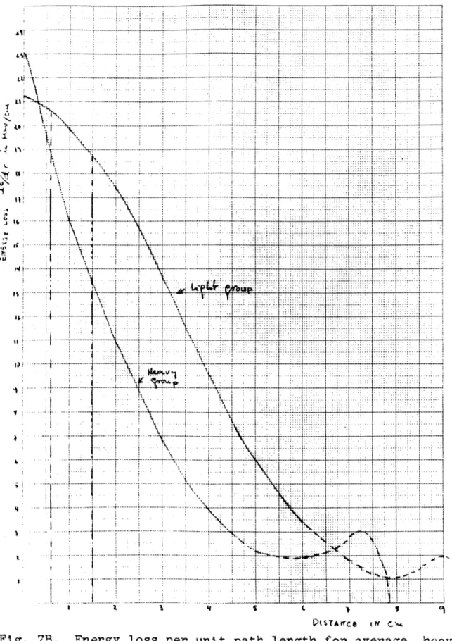
7B Energy loss per unit path length for average, heavy
and light fission fragments from U2 3 5 (O,f). 51
1 Resolution as function of speed in the MTR wire
scanner (from ref. (6), IDO-16243, p. 42). 54 2 View of the scanner from the top of the lattice tank. 55
3 Upper section of the scanner. 56
4 Lower section of the scanner. 57
5 Horizontal motion mechanism. 58
6 Some details of Figs. 3, 4, and 5. 59
7 Side support Part No. 4 60
8 Side support Part No. 13 61
9 Pulley system 62
10 Fission detector support and guide arrangement 63 11 Block diagram of the electrical system 64
12a e Control system 65-69
13 Interconnection diagram 70
14 Modifications in monitor scaler 71
15 Modifications in scanner scaler 72
16 Control panel 73
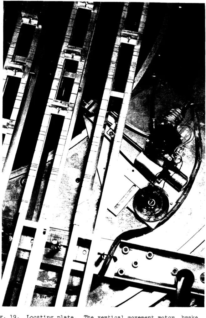
17 Control unit, program unit, and scalers 74 18 View of the scanner inside the lattice 75 19 Locating plate. The vertical movement motor, brake,
magnetic pick-up, reel for winding the cable from vertical limit switches, and electrical connections
Submitted to the Department of Nuclear Engineering on
September 26, 1961 in partial fulfillment of the requirements
for the degree of Master of Science.
ABSTRACT
In the present work a scanner was designed and built
to take measurements of the neutron flux by remote control
at any point in one axial plane of the cylindrical tank which
houses the MIT uranium-heavy water lattice.
The scanner
has two independent types of movement,-radial and axial-and
the displacement of the detector is measured in a digital
controller by counting the pulses produced in magneticpick-ips by small magnets attached to the shafts of the drive motors. The scanner is provided with in-steps type of move-ment, taking the flux measurements with the detector
station-ary. This type of operation is intended to increase the
accuracy and resolution of the instrument.
The control circuit is designed in such a way that a
series of measurements can be programmed to be taken auto-matically at predetermined points in the lattice.
The neutron detector used is a miniature fission detec-tor developed with this purpose. A study of its pulse
characteristics is included in the Appendixes.
The system is able to handle high counting rates. The system also incorporates automatic normalization of the measurements against source strength variations (in this case the MIT reactor). This is achieved by placing another fission counter in a fixed position inside the lattice. This monitor counter and its associated equipment control the counting period of the scanner detector.
Thesis Supervisor: Theos J. Thompson Professor of Nuclear Engineering
Acknowledgements
The author is grateful for many kinds of assistance throughout the development of this work.
The encouragement and human understanding of Professor T. J. Thompson are most appreciated.
The author is also indebted to:
Professor N. C. Rasmussen for his advice on several points. Philip Palmedo who followed this work almost day by day
with many helpful suggestions.
A. E. Profio and all the members of the lattice group. John M. Cornwell who did most of the original drawings. Thomas Green for his able assistance in the assembly of the
apparatus.
David Gwinn who helped in the adjustment of the electronic equipment.
Miss Joan Fisher who revised and typed the final manuscript. A Fullbright Grant from the U. S. Department of State through the Institute of International Education made this work possible during a leave of absence granted by the Junta de Energia Nuclear of Spain, employer of the author. The
equipment and material used was provided by the U. S. Atomic Energy Commission through the MIT Lattice Project.
I. INTRODUCTION
The most frequent type of measurement which needs to be taken on fuel-moderator lattices, such as the MIT uranium-heavy water lattices, is the determination of the neutron density at different points. In order to get the most
ef-ficient possible use of such a facility, it is desirable to
make these measurements with maximum speed and precision. Several methods exist to carry out this type of measure ment including activation of foils, wires, strips, or the use of neutron counters such as B1 0F3 proportional counters,
fission detectors, etc. ( 1, 2, 3).
By far the most common technique is foil activation. The measurement of neutron densities by this technique re-quires the placement of calibrated foils, of a material with
a convenient activation cross section, in the positions of interest. After irradiation of the foils for a given length of time, they are extracted and their activities measured.
In the case of relative measurements, a set of foils with
the same weight and shape must be used. Inaccuracies in
the foil positions, counting, and in the normalization of the
data from each foil make these measurements subject to a variety of errors.
A great deal of work has been done to improve the foil technique and it can be said that at the present time this is the most reliable method for measurement of neutron den-sities The operations involved are very simple and can be adapted without difficulty to almost any particular problem. But the total operation generally requires a long time and, due to the number and kind of steps involved in each measure-ment, makes this method inconvenient when the number of
measurements to be made is high. This is particularly true in D20 systems where it is necessary to open and close the
in-volved have been automated, such as the activity measure-ment by the use of automatic sample changers, but not of the complete operation.
A second method involves the activation of wires or strips and utilizes fundamentally the same techniques although it
is more suitable for relative measurements. The automation in taking these measurements is also easier and has been used in some cases such as the Yankee Power Plant.
A third method makes use of detectors based on the effects due to the products of the nuclear reaction with neutrons "at the instant that the reaction occurs"'.
Ioniza-tion chambers, BF3 proportional counters, semiconductor detectors, fission chambers, etc., form part of this group
of detectors. With this technique all the operations are reduced to the positioning of the detector and the
measure-ment, which generally takes a very small fraction of the time required by the activation technique. By this method, the automation of the measurements seems more feasible. Some of the work done in this direction has been described in the literature (1, 14, _). It must be pointed out that
a disadvantage of this method is that there is no remeasurable
evidence of the event as with the long lived radiative pro-ducts formed in the other methods.
Among the three measuring techniques described in this introduction, the most attractive to the author is the last one; the use of neutron counters or chambers. Conceptually the method which measures reactions with neutrons at the
same time and at the same place as they occur is more straight-forward. This work is an attempt to show that it can be
instrument which could measure the neutron flux distribution inside the MIT uranium-heavy water lattices by remote con-trol with the highest attainable precision.
The most frequent measurements to be taken are radial and axial neutron flux distributions, and the instrument was designed in such a way as to make measurements at any point in an axial plane of the cylindrical tank which
con-stitutes the lattice. A general description of the lattice can be found in eference ().
It is required that the instrument operate with a mini-mum of attention, and it should be possible to program a series of measurements at different points to be taken auto-matically.
As the source of neutrons to be used in the lattice is the MIT reactor, the strength of this source may change with time, and as the measurements at different points are to be made at different times, the measuring circuit must be provided with a means of automatic normalization in order
to get the relative flux distribution.
As the lattice is intended to be used with a number of different fuel rod sizes and spacings, the scanner should be designed in such a way that it can be used with all of them.
7
III. DISCUSSION AND JUSTIFICATION
The scanner to be discussed here consists essentially of three parts: the detection system, the motion system, and the control system. The detectors in the chosen group can be classified into two main subgroups: the pulse measuring devices and the current measuring or integrating devices.
Some of them, such as the fission chambers, can be placed in both groups.
The factors which influenced the choice between these two subgroups are:
1) The average thermal neutron flux. In the MIT lattice this was estimated to be about 108 n/cm2sec.
2) The size of the detector. This should be minimized so as to reduce the perturbation in the flux as much as
possible.
3) The ratio of the maximum to the minimum flux tn the lattice, which in this case was estimated to be close to 100.
4) The possibility of measuring the neutron flux
distri-bution as a function of its energy.
The detectors of the current measuring type having a very small volume give very small currents. It i's felt that
the measurement of the pulses would be more accurate and reliable than the measurement of a very small current and would be less sensitive to insulation troubles which are
likely to appear in a system which would work under water. In the pulse system it is possible to distinguish ad discriminate against pulses produced by other types of
radia-tion which are always present. It is true that the measure-ment of pulses is subject to disturbances generally due to noise, but the size of the pulses produced by the fission
fragments is large enough so that, with some care in the shielding and wiring, it is possible to discriminate against the noise.
All these considerations resulted in a decision to
employ the pulse counting technique utilizing fission counters. The distance from the detector (inside the lattice) to the scalers and amplifiers (on the reactor floor) is approxi-mately 25 feet, and in order to avoid attenuation of the
pulses in the cable to the amplifier, a preamplifier is located as close as possible to the detector (12 feet outside the
lattice tank). The counting chain is completed with a linear amplifier, an ultrafast scaler able to count up to a fre-quency of a megacycle, and finally a printer to record each measurement; this is essential if the operation is to be automatic. (See block diagram, Fig. 11).
As was indicated before, in this system the flux at each point is measured at a different time. If these measurements are made in a given counting time, variations in the power of the reactor, which acts as a neutron source, will intro-duce a proportional error in the measurement. A record of the time of each measurement would allow, by a study of the reactor power chart, correction of the obtained values. This is a troublesome way of making the correction and a poor one also, because variations of the flux in the lattice tank rather than average variations in the reactor are of interest. These are not, in general, the same.
In order to normalize the measurements against these variations in the intensity of the neutron source, another similar measuring channel is used. The detector in this chan-nel is in a fixed position inside the lattice and it is
called the "monitor channel". The scalers in both channels are connected in such a way that both start counting at
exactly the same time and stop when the counts in the monitor channel reach a preset number. The preset number is usually 100,000 or higher so that the statistics of the measurement are very good.
9
In the design of the motion mechanism, it was necessary to decide whether the flux measurements should be made with the detector stopped or in motion. The scanners reported in the literature (, 4, 6) took the measurements while in motion. This type of operation is the easiest to achieve
and requires a simple system, but it has several disadvantages. The movement of the detector while taking a measurement of
a finite length of time always results in lack of resolution. This effect is a function of the speed of the motion, and
also of the neutron flux gradient.
There are no reported examples of the error introduced with this type of measurement with neutron detectors, but a very similar situation arises in the use of the wire scan-ners which are used as another method of measurement of
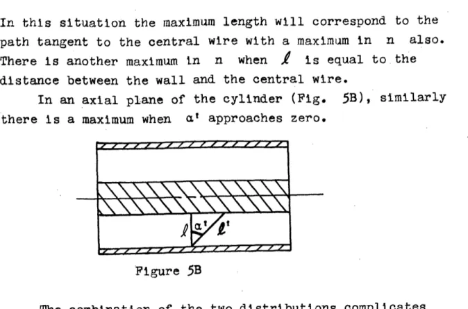
neutron flux distributions. For illustration of the aspect desired, both cases are absolutely the same. In a plot (_.)
of the values obtained with the MTR automatic wire scanner, the measurements of the wire activity were made while in motion. At given points the activities were measured by means of a static method. The results are similar in both measurements when the neutron flux gradient is small, but the errors are large in the case of high gradients.
In Fig. 1 (6 ) there is a clear illustration of the effect of the speed on the resolution. The same wire has been counted twice moving it in opposing directions. It can be seen that the discrepancy between both curves increases with speed but it is appreciable even at the lowest speeds used.
All these considerations pointed to the design of an instrument which would measure the neutron flux with the
detector stationary. The motion is in steps and the measure-ments are taken automatically after each step. This compli-cates both the motion and the control systems but is seems to be worthwhile. This type of operation does not exclude
the possibility of measurements while the detector is in motion.
In order to have complete flexibility, the length of each step can be changed by the operator by presetting the cor-responding value in a preset digital controller which measures
the longitudinal displacement of the neutron detector. The measurement is made using a magnetic proximity pick-up which delivers a pulse to the controller each time that a small magnet attached to the motor shaft passes in front of it.
Due to the previous considerations the speed of motion of the detector is not critical and does not affect the re-solution of the instrument. In the present case the actual speed is the result of a combination of the type of motor
available to fit in the small space inside the tank, the power of the motor, and the necessary precision for the attainment of the preset length of each step. When the digital control-ler reaches the preset value, the motor is stopped and an electromagnetic brake acts, stopping further movement. To obtain accuracy in the position measurement, the following precautions are observed: the measurement of the number of turns is made on the gear reduction train at the higher speed; to get a faster stop of the motion, the brake also acts at a point close to the motor; the mass of all the ro-tating parts, especially of those roro-tating at higher speeds,
is small.
In order to reach any point in the plane in which the instrument is located inside the lattice, the scanner can be moved both in axial and radial directions. To determine the proper speed in each direction, the flux variations that were
expected were considered. In the axial direction the flux changes in a smooth, almost exponential way, without local oscillations, and the distance between points to be measured need not be as short as in the radial direction. In the
ll
variations of the neutron flux are expecte due to the
proxim-ity of the fuel rods.
This local variation or fine structure of the flux dis-tribution is measured in many cases and, if the scanner
is to be used in these measurements, the length of the steps
must be very short. If accuracy is required, the speed must be slower; this means that the equivalent length of each of the pulses, by which one measures the displacement of the probe, is small. With this in mind, the horizontal or radial velocity is approximately a quarter of the axial or vertical velocity. This will be shown later in detail.
It is intended that the plane in which the scanner takes the measurements will be parallel to that containing
the axis of the lattice; it is impossible to take measurements
int thoiaxial plane its-elf as the axial position is occupied
by a fuel rod.
The code for the IBM 709, which will be used in order to compute the buckling from the data furnished by the scan-ner, contains corrections due to the actual distance between the axial plane and the plane of the measurements. This plane should be as close as possible to the axial plane and
the centers of a row of elementary cells should lie on it.
This will allow measurements of the overall neutron distri. bution at the same time as fine structure measurements. The possible directions of the plane chosen are limited to only one, parallel to the control rod, as this plane must be aligned with a row of centers of elementary cells; also due to the fact that the lattice control rod crosses the
tank from one side to the other.
In order to keep the detector in the center of the row
of elementary cells, when the size of the fuel rod or the
spacing is increased, he plane in which the instrument is placed should be moved away from the actual center.
When using the smallest sizes of fuel rods, as the lattice control rod is located between the central and the adjacent fuel rod rows, the scanner will be located between this and the second row from the center. This is so because
it is physically impossible to place the control rod and the scanner in the same space between adjacent rows of fuel rods. When the fuel rod diameter and the spacing are increased, it becomes possible to place both the control rod and the scan. ner together.
More than any other part of the instrument, the support. ing frame and the motion mechanism are adapted to the physi-cal characteristics of the lattice which was designed with a general requirement for the instrument but no specific detector in mind. Thus it must be fitted in the free space, which is extremely small.
As the lattice must be sealed to avoid contamination of the heavy water by ordinary water vapor, and as the cover is spaced less than half an inch over the upper end of the fuel rods, vertical motion is particularly difficult to obtain. Later, the way in which both motions are obtained is explained
in detail.
Basically, the role of the control system is to deter. mine the length of each step of detector motion and the num-ber of steps in each direction, to start and stop the counters, to work the brakes and the printer, to change the direction of motion in a preset order, and finally to stop the motion when this is required outside the limits of the available
space by some error in the program.
The block diagram in Fig. 11 represents the entire electrical system and includes the two fission channels al-ready mentioned as a part of the detection system. Other components are the program unit (Fig. 12), the control unit and the digital controller.
In the program unit, which will be described later in more detail, it is possible to give an order for starting the
13
motion in each of the four possible directions. These are indicated with arrows engraved on push buttons. The posi-tion of the upper corner closest to the control rod mechanism is taken as a reference for this indication. On this unit it is also possible to preset the number of steps (up to 36) to be taken by the detector in each of the four directions of motion. Finally, it is possible to preset the direction to which the scanner will change motion once it has reached the preset number of steps in any one direction. With these programming possibilities, it is possible to obtain, com-pletely automatically, a great number of different
traject-ories of the detector.
The program unit uses relays in its circuits almost exclusively (see drawing, Fig.12a,b).
The digital controller can be preset to any number up to 99,999. Each time a small magnet on the shaft of each motor passes in front of a pickup (a coil with a saturable core) it counts the pulses produced, in this way measuring the motion of the detector. When the count reaches the preset number, the, controller sends a signal to the control unit, which stops the motor and energizes the brake. The control unit also starts the counting circuit in both scalers and, through the program unit, starts the motion of the next
step in the same direction, or the first step in a new direc.
tion if the program calls for that.
Also in this control unit there is a subpanel which allows the starting or stopping of the motion at any point as well as choices between manual or automatic operation and between in-step or continuous motion. It also provides an
indication of the state of the working cycle at each instant. The program and control units are original in design. The scalers have been modified to suit the particular mode
IV. DETAILED DESCRIPTION 4.1 Neutron Detecting Systems
As indicated before, the neutron probes used in the scan-ner are fission counters. Appendix A is a detailed descrip-tion of the construcdescrip-tion and characteristics of the fission counters developed for use in this work.
The simplicity of construction of this type of detector makes it easy to bld a number of different chambers adapted to the different measurements to be made.
The sensitivity of the detectors is particularly import-and in order to keep the counting rate high enough to ob
tain reliable statistics with a short counting time, and yet not so high as to necessitate correction due to dead time losses. Two main parameters can be changed to obtain the
area
sensitivity in the desired range: the surfaceAand the thick-ness of the coating. Fig. 3A of Appendix A is a graph of the sensitivity versus the coating thickness. Once the count-ing rate of a detector with known coatcount-ing thickness is measured
in a given t of conditions it is easy to determine the
correct coating thickness to be used in a detector for that measurement.
The highest counting rate that the system is able to
handle is one megacycle per second. This means that the losses will be very small with a counting rate below 100,000/sec.
The coating in the chambers described in the Appendix was U2 3 5, but recently the author, in collaboration with another student, built three fission detectors coated with
U2 3 8, Th2 32 and Np2 3 7 having different threshold energies
for the reaction (n, f) which allow the determination of the neutron spectrum at different points (, 7 ). No
measure-ments have yet been made with these detectors which have the same physical characteristics as those with a U2 3 5 coating.
15
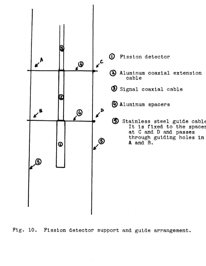
region surrounding the chamber to the least amount, the sup-porting nd connecting parts were designed as indicated in
Fig. 10. The wire sed as a guide is 0.018" diameter 7x3
stainless steel cable and the spacers on the chamber are made of aluminum. The righthand cable is attached firmly to the spacers and transmits the motion to the chamber. The 21-598 type coaxial signal cable is also attached to the driving cable in order to avoid twisting strain on the chamber sup-port due to the force exerted upward by the retracting
mechan-ism on the coaxial cable. The object of the latter mechanmechan-ism is to retract from the region of measurement the excess length of signal cable necessary t reach most distant points. In order to accomplish this, the cable passes over a pulley in the bottom of the upper carriage to another pulley on the upper end of the side support, then passes under a lead
weighted movable pulley and finally up to a fixed point on the upper end of the same side support. Some difficulty exists with regard to the proper operation of this mechanism due to the stiffness of the coaxial cable which cannot be bent to a small radius; the lead weight was included to
main-tain smooth operation.
The coaxial conductor passes through the tank wall using two connectors and goes directly to the preamplifier located outside the lattice tank, but inside the lattice shielding, as close as possible to the detector to avoid unnecessary
attenua-tion of the pulses due to cable capacity.
The monitor detector is located in a fixed position on the side of the tank, and from there on both channels are exactly equal.
The preamplifier used is an N354 Hamner model which is essentially a fast-rise, feed-back amplifier similar to
the well known A-I-D. The rise time is approximately 0.1 psec. The power supply is a 00 V battery connected to the
placed inside the lattice shield and close to the preampli-fier. See block diagram, Fig. 11.
The preamplifier is powered by the linear amplifier. A non-overload linear amplifier with double differentiation (Baird Atomic oedl 215) is used. The discrimination setting of the amplifier was chosen after a differential pulse size analysis using a 256 channel analyzer. This discrimination level was set at the value corresponding to the minimum be-fore the peak on the low side of the pulse distribution curve.
The amplifiers are located in the control rack on the main floor of the reactor close to the instrument panel of
the lattice; the distance between the preamplifier and the
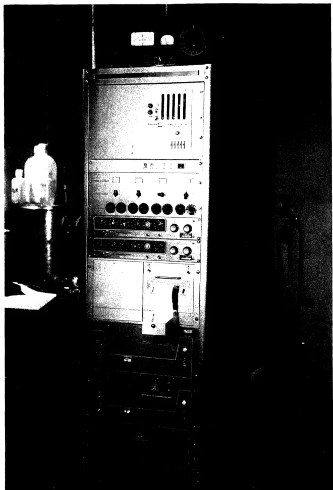
amplifier is approximately 20 ft. The amplifiers are the two bottom units of the control panel shown in the photograph
(Fig. 16).
The PH output of the linear amplifiers is fed into the scalers. These are Baird-Atomic High Speed Scalers', Model 134 and can count up to one megacycle per second. They have: been adapted for the special type of operation of the scanner. The modifications are indicated in the drawing (Figs. 14, 15) and are the following:
1. In the monitor channel scaler:
(a) In section S 101 D of switch S 101, the
con-nection from the 60 CBS test position to ground has been opened and connected to the PRESET COUNT position of the
same section. In sections S 101 B and S 101 A, the connec-tion to the 60 CPS test posiconnec-tion has been connected to the
PRESET COUNT position. The object of this change is to use both the 60 cycle timing and any preset number at the same time, allowing time-controlled measurements.
(b) Pin 1 in-.; 109wag.cnnect'ed to terminal C
in connector J 101. The object of this connection is to ensure that thi other scater'stops!;ounting at exactly the same time. This is important at high counting rates.
17
(c) The connection from S 103 A to T 101 PIN 1 was permanently opened and the common and normally open con-tacts of relay K 101 connected to terminals L and N in J 101. The object of this change was to use this relay to give the print command to the printer.
(d) Pin 7 in V 109 was connected to Pin J in J 101. 2. In the scaler of the scanner channel:
(a) The connection from Pin 1 V 109 and 1K 101 to the rest of the circuit was changed to terminal C in
J 101. This will allow the stopping time to be controlled by the other scaler.
(b) L condenser was connected in parallel with the K 101 coil, the connection from S 103 A to T 101 Pin 1 was opened, and the normally open and common contacts in K 101 were connected to terminals L and N of J 101.
(c) The connection from Pin 7 V 109 to the central contact in S 101 B was opened and the tube was connected to Pin J in J 101. This will allow controlled closing of relay K 101 with the other scaler, but with a delay to allow the completion of the printing cycle. This relay is used to reset the digital controller and both scalers.
This scaler has been modified to furnish the correct information to the printer used.
The printer used is a Hewlet-Pakard model 565A. It receives information from the scaler in the scanner channel,
printing at the command of the monitor scaler; a set of
contacts of its disable relay is used in parallel with the reset circuit of the scalers as indicated in the drawing (Fig. 13). This is done to avoid any change in the input information during the printing cycle. The length of this printing cycle is 200 m sec. and the reset of the scaler must be delayed for at least this length of time. This is the
role of the condenser in parallel with the coil of relay K 101 in the scanner channel scaler.
4.2 Supporting and Motion Mechanism
Essentially the supporting frame is formed by four parts, each limiting one side of the axial plane in which the scan-ner will take measurements. Figures 2, 3 and 4 can be
used as general references for this description. The first is a top view of the scanner inside the lattice tank and the second and third are side views of the scanner in the same position.
The basic material used is 1100 aluminum. All screws used are 304 stainless steel and most of the threads in the aluminum carry stainless steel inserts to allow repeated use.
4.2.1 Support
The description can be started with the left side
sup-port shown in Fig. 8 marked No. 13 in Fig. 3 . All the details of this part are indicated in Fig. 8 . Its total
length is 67 1/2", slightly shorter than the lattice tank.
It was designed in such a way that all the components of the
scanner could be removed from the lattice as a single unit with a small number of location points. This is the object of the plate welded to the long arm. Located on this plate are the motor, the brake, the reel for winding up the cable leading from the microswitches in the movable part, the mechanical transmission, connectors, and finally, the slots for the three location screws;.
The bottom end of the supporting frame is held in posi-tion against the lattice wall by a spring-loaded cap (Part
No. 21), indicated in Fig. 4 . It is believed that the
supporting structure is rigid enough so that no other fixed connections (which would have made the installation of the instrument inside the tank difficult) are necessary.
i9
The length of the location slots was calculated taking
into consideration the different
types of fuel rod-moderator
configurations to be used in the lattice.
The fuel
rod-moderator configurations were also taken into consideration
in the design of the size of the bottom spring-and-cap
posi-tioning
device.
The right side support is essentially the same as the
left one in its section inside the tank. The shape of
locat-ing plate welded to the right side support is determined by the existence of the beam which supports the control rod
(Drawing in reference (5)) and which has a cross section
indicated in view D-D of Fig. 6 . The details of this part are indicated in Fig. 7 as well as in views A-A and B-B of Fig 5
The bottom side support, Part No. 24 in Fig. 4 , is an aluminum rod which acts as a guide to the bottom carriage which will be mentioned later.
The upper support is a 0.5" splined rod. The material is stainless steel for making the assembly rigid and allowing very little vertical deflection. The object of the spline is to guide the upper carriage and to maintain its vertical
position at all times. The spline, Part No. 1, is shown in Fig. 3
-4.2.2 Horizontal Motion Mechanism
The horizontal motion is powered by a split single phase motor, BODINE TYPE K-2 115 VAC, 11 watts, 280 RPM. The
posi-tion of this motor is indicated in View A-A of Fig. 5 . Its shaft is coupled to the intermediate shaft, No. 33 in the
same view, through pinion No. 32, idle gear No. 31, and Pinion No. 32. In turn, this shaft transmits its motion to the screw horizontal drive, a 4 ft long stainless steel screw
indicated as Part No. 2 in Fig. 3 ; through the worm, Part
re-spectively. The speed ratio in the worm and worm gear is
10 with a resulting speed of 28 RPM in the horizontal drive
screw,
This horizontal drive screw is supported at both ends by bronze bearings inserted in the aluminum lateral supports. Its rotary movement, acting upon a nut fixed to Part No. 14
in the small carriage shown in bout the center of Fig. 3,
is converted into longitudinal movement of the carriage at a rate of approximately 1.55" per minute. The neutron detector is supported in this carriage and moves along with it, as will be indicated later.
In order to move the detector always in a vertical posi-tion at any height inside the lattice, another fixing point in vertical alignment with the upper carriage is needed. This point is provided by the lower carriage (Part No. 27) indicated in Fig. 4 about the middle of the bottom support. This lower carriage is made of nylon in order to minimize the perturbation of the neutron flux coming from the bottom of the tank, and at the same time reducing friction against the bottom support rod over which it slides. This carriage is moved by a system of pulleys and cables which can be seen
partially in Figs. 6 and 9.
The pulley and cable system is symmetrical about the vertical line joining the center of the upper and lower car-riages and it is formed by two cables of equal length. One
of them (Fig. 4) starts in the eye bolt, Part Noo 28 in
the lower righthand end of the instrument, and goes to the
pulley, No. 25 on the righthand side of the lower carriage.
From there again to the lower righthand corner on pulley No.
19, then up to the pulley indicated in Fig. 5 , view A-A as Part No. 19, From this point the cable crosses to the left side support, passing through a hole in each of the side
supports of the upper carriage. At the lefthand side, it passes around two pulleys in the assembly, Part No. 35 of
21
Fig 6 , then to the pulley (Part No. 39) fixed to the left
side of the upper carriage, and finally ends in the eye bolt
(Part No. 28) on the left side support,
A second cable traces a path symmetrically opposed to the first. Figs. 6 and 9 are an attempt to clarify this
description; one of the cables is in blue and the other in
red. The cable used is stainless steel of the same type as that mentioned in connection with the detector support.
As a result of this arrangement, a movement in the
upper carriage is accompanied by an equal movement of the lower carriage, keeping the center of both always in a verti-cal line. This cable arrangement may appear complicated,
but, in fact, it is only about 4 ft. longer than the minimum
possible length (14'). This increase in length makes the linear movement of the cable twice the length of that moved by the carriage. In other words, the tension in the cable
is reduced to one half by an increase in length of 23%o The result of this will be an increase in the accuracy of the
position of the lower carriage with relation to the upper one. An important part of this motion system is an
electromag-netic brake, indicated in view A-A of Fig. 3 (Part No. 57) coupled directly to the motor shaft. This is a STEARNS
brake, 28 volt DC, with a torque of 28 lbs/inch which is
strong enough to stop the motor instantly. 4.2.3 Vertical Motion System
A motor (Part No. 46) identical to the one used for horizontal motion provides the power for vertical motion. It is fixed on the locating plate welded to the lefthand
support as indicated in the upper lefthand corner of Fig. 7.
The motor shaft motion is transmitted to the extension shaft (Part No. 8) in the same drawing by using two miter gears with a ratio of 1/2. Two aligned bearing blocks (Part No. 9) support this shaft, which is coupled at its right end
to a pinion (Part No. 7). This pinion, held in position by a bronze bearing (Part No. 37), is coupled to the gear (Part No. 10) on the left end of a long stainless steel spline
(Part No. 3) and located below and parallel to the horizontal drive screw. The gear ratio-;of Parts 7 and 10 is 1/4.
The spline (Part No. 3) allows for the horizontal free movement of the splined worm(Part No. 53) on it inside the upper carriage, at the same time that it transmits its
ro-tational movement to it. This worm is meshed with the nylon worm gear (Part No. 4) which, at the same time acts as a pulley over which a cable passes which guides and drives the fission detector. This cable forms a closed loop between
this pulley and the two small pulleys located on the bottom
carriage (Part No. 40).
The cable is attached to one side of the neutron detec-tor support and passes over the pulley and back down through guide holes in the support in such a way that when the motor rotates the worm gear-pulley rotates, and its drag upon the cable makes it move causing the vertical movement of the
neutron detector. The two small pulleys in the lower carriage are mounted on a stainless steel bracket which acts as a
regulator of the tension on the cable. 4.3 Limit Switches Arrangement
Positive action limit switches are used in order to avoid damage to any part of the mechanism s the end of the free travelspace and to act as reference positions. The
limit switches for the horizontal motion are placed on the lateral supports such tat they are actuated by the side plates in the upper carriage, and they are above the water level.
The limit switches for the vertical travel must be
placed on the movable carriages, but as it was not advisable to put the lower one inside the heavy water, both switches were placed on the lower side of the upper carriage. The
upper limit switch is actuated by the chamber support press-ing against a small arm. The lower limit switch is placed inverted in relation to the other and both are held on the same bracket. The arm which actuates this switch is linked to the end of a cable parallel to the cable which drives the
detector; the other end is connected to the lower carriage.
This cable passes through a small hole in the chamber support
and its lower end is knotted in such a way that where the
detector is close to the lower limits its support hits the
knot andpulls the cable which activates the limit switch,
stopping the movement in this direction.
The cable connecting these two limit witches to the
outer circuit is taken up on a spool located on the
position-ing plate on the lateral support.
This spool is spring-loaded
in such a way that it maintains constant tension on the cable.
Three wires connect each limit switch with the rest of
the circuit.
This makes a total of 6 conductors to be taken
up by the spool. A cable with this number of conductors is
too rigid to be taken up easily on a small size spring loaded
spool.
This problem was solved by using two DIC
relays
assoc-iated with 4 diodes in a circuit (Fig.12-C) which is sensitive to current direction. In this way it was still possible to obtain the same output information, although the number of conductors from the two microswitches was reduced to two.24
4.4 Control System
This is the system which controls the series of move-ments and measuremove-ments. Its main components are the pro-gram and control units. Also included are the digital con-troller and part of the printer and scalers.
4A1l Program Unit
The program unit shown in Figs.12a and 12b and in the photograph (Fig. 17) is the largest unit, at least in number of components. It is mainly a relay unit and it can be di-vided into four very similar circuits, one for each of the four possible directions of motion. In the figuresthey are divided into two groups of two directions, each with a common motor able to move in two opposite directions. In Fig. 12a are shown the circuits for the two horizontal directions plus those common to all four directions of possible move-ment.
As an example, the first circuit corresponding to the
horizontal motion in the direction from the control rod towards the reactor will be explained. If push button PB1 is pressed, the circuit across the relay Rll will be closed, and this in turn will close the set of contacts lRlli parallel with PB1, thus holding its circuit closed once it has been pushed. The same effect can be obtained by the circuit paral-lel with the push button,formed by 20TBlA, 2R31, 19TBlh,
14TBiA, :and'2R2-;: -. when the movement transfer switch MTS1 is in position 1, as will be explained later.
At the same time relay Rll will close the set of contacts 2Rll in series with the motor. If the series of contacts
STOP/RESET, 2CR1 , LS1 and 3R32 are closed, the motor will start moving the detector in the direction controlled by
this circuit. This means that the motion of the probe is
posi-r
tion, if the control unit is asking for movement, if the de-tector has not reached the limit switch in the direction in
which it is required to move, and if the motor is not moving opposite to the required direction. Then the motor will continue to move until one of these conditions is changed.
The motor M1 is a single split phase 11 watt motor and
has two coils with a common end. The other two ends are connected across a condensor. When one of the coils is
connected across the power line, the other coil is supplied 90 outfpaand
with a 90° out of phase currentA the motor rotates in one
direction. If the line is connected to the other coil, the
motor rotates in the opposite direction.
At the same time that the motor starts moving, the re-lay R31 in parallel with it is energized with the following results:
(a) The contact 1R31 set in parallel with 2Rll is closed,
keeping the motor going even if 2Rll is open, which may happen under certain conditions.
(b) 2R31 closes, causing the stepping relay switch
SRll to advance one step if the AUTOMATIC/MANUAL switch is
in the automatic position and if the STEPS/CONTINUOUS switch is
in the step position.
(c) The same set of contacts 2R31 opens the circuit
between 20TB1A and 19TBlA. This stops the transfer circuit, which includes the transfer switch MTS1, from transfering
the movement to another direction while the motor is moving. (d) The set of contacts 3R31, in series with the circuit bringing power to the other coil, which moves the motor in
the opposite direction, prevents the motor from being driven
in two opposite directions at the same time.
(e) Finally, the set of contacts 4R31 energizes the
brake, allowing movement of the motor and stopping it as soon as relay R31 is de-energized.
26
The selector switch indicated in Fig.12a and in detail
in Fig. 12e, allows selection of the number of steps by chang-ing the position of the two switches to any desired number of steps in one direction from 1 to 36. When the preset
number is reached by the action of the stepping relay, as indicated in paragraph (c) above, or when the probe reaches the limit position by actuating LS1, the circuit in series with R21 is closed and this relay energized, unless the switch
AUTOMATIC/MANUAL is in manual position. Closure of this relay causes:
(a) Opening the set of contacts 1R21 and de-energizing
relay Rll, which means that in future steps the probe will
not be moved in the same direction. As a consequence, the
set of contacts 2Rll will open. If the limit switch LS1 is actuated, the motor M1 will stop immediately because this
switch is in series with its circuit. At the same time this will de-energize R31, and this will be followed by the conse-quences listed in the next paragraph. If, however, R31 is energized across the NUMBER-OF-STEPS SELECTOR, the movement will continue until the preset length of the step is com-pleted and the motor and relay R31 are de-energized.
(b) At this moment, the set of contacts 2R21 is closed
and 2R31 is closed also. In this way the circuit, in paral-lel with the push button in the direction of motion selected in the switch MTS1, is closed and the motion is transferred to the new direction.
(c) The set of contacts 3R21 will close and the reset coil of the step selector is actuated. When this happens, if R21 is energized across the NUMBER-OF-STEP CIRCUIT, this will open, R21. will be de-energized, and 3R21 will open again. It was found that the time in which this sequence of events
takes place is not long enough to allow the stepping relay
to be reset to zero, and t';, circuit,
including the condenser
27
diode and resistor, was placed in combination with SR12, caus-ing a delay of the order of a second, long enough to allow
the resetting to zero of SRll Fig. 12a.
The circuits corresponding to the other directions are similar and do not require further explanation. But it is worthwhile to point out that use was made of as many common points to as many circuits as possible in order to aold the repetition of components. Careful study was made of all the conditions included in the design in order to avoid unneces-sary complication.
4.42 Control Unit
Comprising only a small number of components, the control unit is used as an interconnection center of components lo-cated in each of the other units, and at the same time, some of its components have been shown in other circuits in order
to simplify the presentation. Its function is described
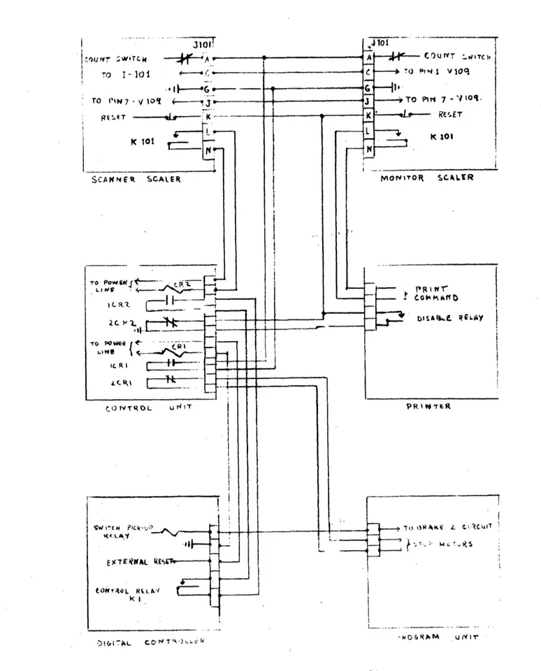
by the control interconnections diagram in Fig. 13
In order to facilitate the understanding of this diagram,
the order of operation will be described.
When the push button for movement in a certain direction is pressed, the motor starts moving in this direction and its displacement is measured by the digital controller with the input selected by the circuit indicated in Fig. 12c. If the preset number in this controller is reached, the control relay is activated, closing the contact set indicated in the diagram, which is connected in series with the power to the relay CR1 in the control unit. Energizing this relay causes
closure of 1CR1 and the opening of 2CR1.
lCRl is connected across terminals A and G of both
scal-ers. When it is closed the counting in the scalers starts.
2CR1, shown also in the circuit of the program unit, opens the circuit in series with all the motors, in this way
de-energiz-ing R31, R32, R33 and R34.
When the monitor scaler reaches the preset number, the
connection from terminal C in J101 to the same terminal in
the scanner scaler makes it stop without measurable delay. At the same time closure of the contact set in K101 connected to terminals L and N and to the printing command input in the printer causes it to print the information received from the scanner scaler.
Simultaneously connection from PIN 7 in V109 through the terminal J of J101 in the monitor scaler to the same point in the scanner scaler causes actuation of the relay K101 in this scaler. After a short delay, closure of the lK101 set of contacts energizes the control relay CR2.
Contact set 2CR2 is opened. It is in series through
connec-tion K in J101 with the reset circuit in both scalers. It
is also in parallel with a set of contacts of the disable
relay in the printer. The reset action does not take place until the disable relay is-de-enrgized once the printing cycle is completed. At this time the reset circuit is opened and both scalers are reset to zero. Relays K101 are de-energized in both scalers and the reset circuit is closed again.
Another set of contacts, 1CR2, in CR2 is closed
simul-taneously with the first opening of 2CR1, causing the digital controller to reset which in time starts the motor for the next step through lCRl shown in the program unit circuit.
29
V. OPERATIONAL PROCEDURE
Once the desired length of each step in the horizontal direction is determined, the preset value for the numerical controller will be found by using the equivalence, 1" =
.360
counts. The value found will be put in the selector of the numerical counter.When setting the counter in the lattice, a diagram
should be made noting exact locations of the reference limit switch with relation to the closest fuel rods. If the length
of the steps is to be related to some dimension of the lattice
in such a way that measurements are to be taken at equivalent points in each cell, it should be remembered that the
detec-tor must be positioned, before starting the automatic mea-surement, at the point to be measured closest to the limit
switch.
The next operation is to select the number (up to a
maximum of 35) of steps to be measured in each of the direc-tions of movement. If it is desired to maintain a certain
relation between the points of measurement and the elementary cells, the number of steps in each direction should be pre-set in such a way that the detector does not reach any limit switch. If this happens the direction of movement will change but the digital controller will continue adding up counts
to the preset number, from then on losing the relationship between points and the elementary cells of the lattice.
If the desired number of steps is more than 35 it is
naa'V I-,- m1rk tlh& rr nml mja UJ.n aSLrQc- V. 'h IhJ 1mi iJ. t wil tr h
rlvvvou lr vv vw ;^acon - l Fl E i LO V.L -. I V ri 0 % V W 1w V - I
This can be done by switching the CONTINUOUS/STEPS selector
to the CONTINUOUS position. The next step is to select the
direction to which the movement will change after completing the preset number of steps in each of the directions involved in the program. This can be achieved by turning the "Transfer to Direction" selector (Fig. 17 ) until it points to the new
direction. This operation is repeated in each direction
involved, If it is desired to stop the movement before the
preset number of steps are completed in a given direction,
it is necessary to set the transfer selector to indicate its
own direction. When the detector reaches a limit switch of
the AUTOMATIC/MANIJAL switch and is in the AUTOMATIC position,
the instrument will change its direction of movement to that indicated in its transfer selector. The movement will stop
completely if that switch is in the MANUAL position.
In order to start the movement it is necessary to
de-press the push-button with the arrow indicating the desired direction. From this point the instrument will develop the preset program starting by moving the detector one step.
If it is desired to start the cycle with a flux measurement, it is necessary for the digital controller to have its
con-trolling relay energized (red light illuminated). This can be achieved by making the numbers indicated in both counter and preset register coincide for a moment before starting the cycle.
The operation cycle can be stopped at any point by press-ing the STOP/RESET switch to the STOP position. The circuit of this switch is such that the program will continue on from.
this same point when the switch is depressed again to the RESET position. This stop will be counted as a step in the direction of movement by the stepping circuit. If the preset number of steps is to be maintained, one unit should be added
to the preset number each time that the STOP switch is actuated. The stepping relay is not designed for continuous
opera-tion and, as it is energized during the movement of the
de-tector, the program should be stated in such a way that the periods of continuous movement are not longer than 5 minutes when in both AUTOMATIC and STEPS types of operation. To alleviate this problem a resistor with positive coefficient of temperature is used in the circuit. The AUTOMATIC/MANUAL and CONTINUOUS/STEPS switches also prevent the operation of the stepping relay when It is not necessary.
31
APPFNDI A
Neutron Detector
In order to produce the minimumn
disturbance of the
neu-tron flux, the size of the detector has to be as small as
possible.
For this rason,
two map! types of detectors
3eemed
best suited: the proportional and the fission counters.
The BF
3proportional
counter was discarded due to the
corripli-cation of the handling of the gas and also the discrimination
against the gammas being more difficult
than in the case of
the fission counter,
The cylindrical
geometry design was
chosen for its ease of construction and good pulse
character-istics.
Principle of Operation
The cathode of the detector is lined with a very thin
coat of fissionable material, When
this is irradiated with
neutrons, the fission fragments released spend most of their
energy ionizing the gas filling the chamber, The electrons
released in this process are collected by the positive central
wire in which they produce a voltage pulse; this is amplified
and counted in the associated electronic equipment.
The energy distribution
of the neutrons can be obtained
by using fissionable materials with different threshold
energies.
Descriotion and Construction
Central Wire. This is a 1/32" aluminum wire.
It is the
central conductor of a coaxial aluminum cable insulated with
A1
20
3powder and is also used as the electrical
connection
between the counter and a miniature coaxial cable.
The
ob-ject of using this aluminum cable, which has a 1/8" outside
diameter, is to
avoid
the use of the normal coaxial cable
whose central conductor and shield of cooper have a igh
absorption cross section for thermal neutrons. It has a otal length of 5" and could be used as an electrical connection
with the preamplifier. But in this experiment, since the
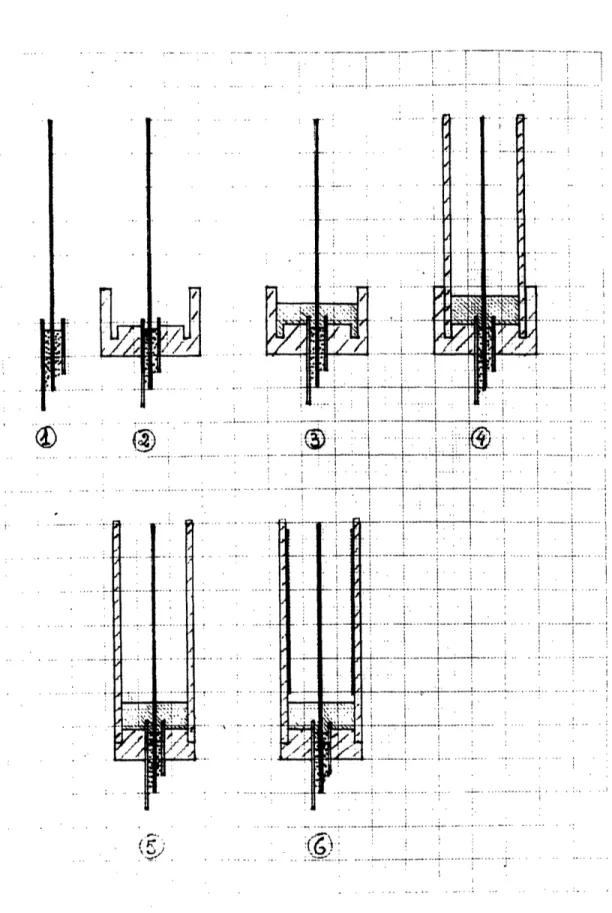
counter was to be used as a movable detector, a flexible con-ductor was needed. In FiglA-lthe aluminum cable is shown; the
external Al tube and the insulator have been removed to a
length equal to that of the counter.
In Fig.lA-2 it can be seen how the Al cable is inserted into the central hole of a small Al piece which serves as a mechanical support and electrical connection between the
out-side counter tube and the shield of the Al conductor; this
closes the ground side of the circuit.
Insulator. The choice of an insulator is a delicate problem which depends strongly upon the conditions of
opera-tion of the counter. Considering the resistance to radiaopera-tion and temperature, ceramic insulators are best, but their very small expansion coefficients make it very difficult to seal
them hermetically to most metals. The Kovar glass seals are easier to weld to metals. Some plastics have very good
insulating properties but their resistance to radiation and temperature is not very good. However if they are to be operated at normal temperature and in a low radiation flux, they make an excellent choice and are used frequently in this type of detector (lucite (8), and teflon (.9)). Taking
into account the present operating conditions, it was decided
to use a plastic.
After a study of the properties of the possible plastics,
a "CIBA" resin, known commercially as "Araldite" was chosen. Its electrical properties are satisfactory. In the follow-ing table (10) the different properties of "Araldite" are shown compared with those of "Teflon", another plastic used
Araldite Teflon Energy absorption in Rad/109 thermal 0.7 1
neutrons/cm
Exposure for 50% decrease in the most 4 0 003 sensitive mechanical property, in 109 rad
NVT, thermal neutrons/cm2 (reactor radlation)15x101 8 3xl?5 Equivalent to 1 year at a flux of r2xl0l l lxl08
Another property of "Araldite" is that its welds to
aluminum are vacuum-tight. This plastic is prepared in 11i quid form by mixing in appropriate proportions the main com-ponent and a polymerizing compound. It hardens slowly in a time which is a function of temperature but which varies from half an hour to a day.
The setting up of the upper insulator is illustrated in Figs. 1A-3 and 4. As indicated in Fig. 1A-3 with the counter pointing upward, the liquid plastic is poured in place and the level set a little below the desired level, as it will
increase when the next component is put in place.
Counter Tube. This is a 1" long piece of standard
al-uminum tube of 3/16" ID; it is put in place as indicated in
Fig. 1A-4 and encased in the groove under slight pressure. The counter is left in this position for 24 hours in order to allow the plastic to polymerize. It is more con-venient to carry out the polymerization process slowly be-cause in this way the weld to the aluminum is better. Also, all the gas bubbles trapped in the counter walls and bottom can escape.
The following day a lathe can be used to cut off the excess material in the Al supporting piece as indicated in Fig. 1A-5.
I
I
:/ ... .
t iw.
;/t
E , 0..
... ..
Fig. iA. First steps in the assembly of a small fission
detecto
.
i · li
I i i i . -·-- -,---+--·--·---tlcr----···-·---r · :...
...
...
;...
... ... ... :... .. · ·· ·- - ·- -- ·--- ~--- · · ·-- · - ·- tf---'·--+- · ~ - --- 7--- ...-. ... .. .. .. . .. . .. .. r ·-t ·----·--- ·--- ·- ... - - ·.. . · -·35
Uranium Coated Platinum Foil. Two main methods for
obtaining uranium coats over different materials are reported in the literature ( 8, 11). These are the electrolitic and painting methods. The first one seems somewhat better since no foreign material is deposited at the same time as the
uranium, in this way avoiding absorption of part of the
energy of the fission fragments. However, this method re-quires more equipment and time, The painting method is perfectly adequate for the present detector chamber.
The painting method is described in detail by Rossi and Staub (8 ). In the present case the concentration of the UO2N03 solution is 5 mg/cm3 instead of the 50 mg/cm3 reported
by them. The coating is made over a 0.001" thick platinum foil and after each layer it is baked at 9000°C for 2 minutes. To obtain a thickness of 1 mg/cm2, this process must be re-peated a minimum of 20 times. The adherence of the coating is very good and the foil can be bent withoutthaving it peel off. In the counters built, the thickness of the coat varies from 0.33 to 2.75 mg/cm2
Once prepared, the foil is slipped inside the counter forming its cathode. This is shown in Fig.lA-6.
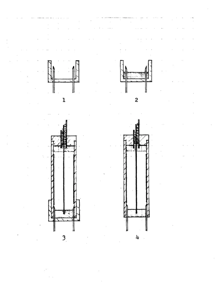
Closing of the counter* It is necessary to first put the second insulator in place. This is done with the counter inverted with respect to the first operation. To obtain a vacuum od gas filling system, two hypodermic needles are fixed and left in place through this insulator. They are held in place by a polyvinyl plastic cup as indicated in
Fig.2A-l. Next, plastic is poured in this cup and the level set as in the previous insulator (see Fig. 2A-2). The next
step is to place the counter over this system and leave it, as in the previous case, for a day.
3
37
wire is a little shorter than the outside walls, in order that it terminate within the mass of plastic and avoid all problems of surface contamination and loss of insulation.
Once the counter is closed, it must be evacuated and left in this condition for a long time in order to remove the greatest amount of the gases absorbed in the internal surfaces. During this process the counter must be heated up to 70 or 80°C in order to reduce impurities. This baking out is essential for good counter operation.
The counters were filled with argon mixed with a small percentage of nitrogen. This mixture gives good pulse char-acteristics and stability with time.
If the counter is not exposed to excessive fluxes, it is likely that the life of the counter will be mainly de-termined by the care with which it is evacuated, filled and closed. Therefore these operations should be carried out with great care.
Effect of the Thickness of U2 3 5 Coating on the Sensitivity
Three counters were prepared with different thicknesses of the U2 35 coating. In Fig. 3A the resulting sensitivity is plotted against the total amount of U2 3 508. The total
3 8
amount is used because it is difficult to be certain about the homogeneity of the coat. As an approximation, the values of the thickness (mg/cm2) are also given. It was expected
that the sensitivity would increase with the thickness be-cause this range is far from the mean range of fission frag-ments in U308 which is 10 mg/cm2 (see reference (12)).
The position of the neutron source and the counter was the same in all the measurements taken.
Electrical Character stics
The operation voltage of the counters is 300 volts, but
I __ .. I __ ___·1 _·_d_ __
... .. ...
-- -.:
:-I- -:
...
,
: - I :i~ , , z .1 .-t9,:!_
- -~!: I ! .. . : I': : i ... : ... ... :--!---. 7- --. ... : I . ... . ... i : " ' I -: W.- i_L .... ---I 7 leJ !..: k-.' . . -'";--, ·. -. q .. '.; i :: . 0~~~~~~~~~~~~~~~~~~~~~~' . i..O. . .:: ., . . . .... . .- ! :- -~ -- --- I . .. 1. :1 1. ....'.: -. --.... -.. , ; I ::: : ·-: ;,:· _1: -i:1_ "':': : . r : , :---m , , I.... 7, . : . I . . .. :AI ' . : .: Ii --. .:-:O :" t · ''& oi '-:-t -"-I_
i L .._'.... ...--
I-
.... -.--...- .;. . ---I .. I i i .l I : -! : ' I I ...i...
"4 .- I::: i l ii i :.. ... ~.-; .- - ....t ..':::_:: ::.. ... .... ... .. ':'....'. I'_... . . :i'":' ' I': -" "'i i .... ... :-. I ... . ~: ~- ... .. ,. -, . .·. . . . . i!::ii:i! · : .. . . :' . . : .. - .:. . . I .. r , : . , -! :.:, ' - ::'. .. · . i . ..I . . ·. . ' : I . . --.. ... .... ... : "''" . +_...- · 1 . . I .. . . . .. . I · .I.- .I ... I ... I :: i: 1777 177 77 : . ' I : :I:',::' :
:--
...
: ...
-i...
I
:.I . .-- :::m, .1 .... i --~~. F.¥-: :-: :.;: :: , ::::::. . . . .. :Fi:-'t: .i. : i- iF: ;.:--: t,. .. I. , ::iii, ' .''; ... . . : . ..' ..::'.1 F.! :': . ... .' .) I ' - ...-..: !. i .: i 1.. ... ..
: · . : . : .. f: : : : i : : : : · · · r : : : : : --··- · ···-: -···-: r ···-: I - ···-: ···-: ···-: t ···-: ···-: ···-: ···-: '''''''' " ````'``" :::::::::: : :: : ::':-,-....,- ~ --:i '" -:':-:L: .. ....·
::.,~
...
:::
...
:
t_,:,....::~
~ ' i ,i t':
'-i :::::::::::!:::::::'+',.I .'!:'.. i' -- · i ...~ : . ! i . I.:'
i.:- 7':::'
... :.;;::;/..::':... ...
' ' : ~~~~~~~~~~~~~~~~~~~. '... I ' `" : '-~ i -~.-.~...-...-, i ~~~~~~~~~~~~~ 1~~~~~~~~ ~.~-:..- .-. f.--: ... .... : ~ ...i..:. ... ~= " . ,i ~~~~~ll--~~.~~--~~I.... .'1 .:...~.. .. .~ ._- :'i ... ~ ... . ~~~~~i-·- ... n .... i. , [ · x -- --- - -· ! i T . f · -· ---·· · · -· · -- 1 ·- --- ·--- -- ·---· · ·- --- z X --- --- f --- 1· ~~~~~~~~~~--- ---c--+----·i ---. -- C-- -·-i::.:ii:rliiiiii:-li :: ... 1.. i. I i ·~ ~ ~ ~ ~ ~ ~ ~ ~ ~ - - - - --- -- - --- -~~--~.... -...
l-
--
go
a- a
-'
·
..0
f
r
~ .
i, ..-
i ,.-.c...:... ...--. i...,.. .. :-. I : ...~.. ~-.; .... ... ; ... ; ... "::... . I. .I I . ' ' i 0 00 0C UIN CCl 1.r
r-4 co 4--0~ ILI . 4)r -P i .-: :i '-' · t. -' t ... : i.. .- .i . : m . ... .. , .i....~~~~~~~~~~~~~~~~~~~~ -j 1-::.:.;;: ~::::':I::. .!-:.:.' :: : ..,...::::::-.':: ::".... ::: ::
...
:
::: '. ' :::I ':-:J ::::-::: : : : :: : : : : :: ::: ... : ..:.
I.:-:"
:'I
1
:
...I ... :'":
;.:::" :1: I:.-:]::,:::t'. :: : : ;;...""; : . . .t:;: :. :::'. : I , : ::::::::::::::::::::-::.: l:' .:' . :. . -: -.. :: .... .. !::.. . : :i: .:i.'. -- i . :'I ir .. .M. . .. ... .. ... .. ... .. . '7;. : - : : -': . ..: .1 .t': ..:. . .... :: . .::. ". ' I ' ! ... - ::. : '' ' .: ' .... ': ... . 1'' : ::.':! . :"- j:' : I: ::. . I :: ; ' ::::': ' :.... . ...":'"' '.: :'' ': I : : ,:::l i i :.. : :: ,% -:'i .. : : i: ;i ...': . :::::::: I I '"::::!':::"':: ::::: :: ·i .'_ :-'· :-:: :-t~:" ...- .:":*,:::. ---'t:-t-:':"':::':..:... .: !' :.:.-77'~ ~ :: :!~: ;I' i i : ' .- %-!- : L ' ' ' -. I I' . . ... ..:-': -::'i:::- !. : : - i::-1: I - - I I.I t. L -: . ii : . . .::'".I . : . . . ; M . . .:.1. 1. .. I . 1 . I ' I ... t::-l . .. :. .: : . . ... :: :. - i ii .. .ii : :-:: :i. , :: ; .. ... Cl--·-·· ;--~i .... P O ... -L...._... .O O L.. ·... __~~~~~~~~~~~~~~~~~~~~~~~~~~~~~~~~~~~~~~~~~~~~~~~~~~~~~~~~~~~~~~~~~~~~~~~~~~~ . 0r