Design of a Formed / Folded Compliant Layered Mechanism By
Nathan M. Landsiedel
B.S., Mechanical Engineering (2001) Purdue University
Submitted to the Department of Mechanical Engineering in Partial Fulfillment of the Requirements for the Degree of
Master of Science in Mechanical Engineering at the
Massachusetts Institute of Technology February 2005
C 2005 Massachusetts Institute of Technology All rights reserved
Signature of Author...
Department of Mechanical Engineering January 3, 2005
Certified by, ...
Martin L. Culpepper Roc well Ifernational Assis Professor of Mechanical Engineering Thesis Supervisor
A ccepted by... ...
Lallit Anand Chairman, Department Committee on Graduate Students
BARKER
Page 1 MASSACHUSETTS INSTITUTE OF TECHNOLOGYMAY
0
5
2005
LIBRARIES
Design of a Formed / Folded Compliant Layered Mechanism by
Nathan M. Landsiedel
Submitted to the Department of Mechanical Engineering on January 3, 2005 in Partial Fulfillment of the Requirements for the
Degree of Master of Science in Mechanical Engineering ABSTRACT
The purpose of this research was to investigate a new method and a new practice of engineering low-cost, actuatable mechanisms. This work investigates the theory and practice which are needed to lay a foundation for the design of actuated mechanisms that consist of discrete functional sheets. The various requirements of traditional, functional components are embodied in sheets, or layers, of material rather than in discrete components (e.g. actuators, links, gears, etc...). The functional layers are designed to be bonded together in a way that forms an actuatable mechanism. These compliant layered mechanisms, CLMs, consist of four layers: (1) a skeleton cut from a single sheet of material that provides structural elements and compliant amplification mechanisms, (2) actuation, (3) control circuitry, and (4) sensors or other functional components as needed. This thesis presents the design, modeling, fabrication, and experimental validation of the
CLM concept. Precision machines with integrated stiffness characteristics, actuation, and control circuitry are realized through forming / folding the CLM sheet. The CLM is implemented in a five axis nano-manipulator capable of a range of hundreds of microns and a resolution of tens of nanometers. The CLM manipulator is modeled using a node/beam stiffness matrix in CoMeTfm. The performance of the manipulator and the
accuracy of the model are verified through a series of experiments in which the manipulator is made to translate (Y and Z) and rotate (OX).
The skeleton of the CLM utilizes thin elliptical compliant amplifier mechanisms (TECAs) to provide amplification and guidance of the actuators. The behavior of the TECA is shown to be governed by the transmission ratio (amplification) and the ratio of the width to thickness of the flexure elements. A parametric design tool was developed enabling designers to predict and control the performance of TECAs subjected to a combination of desired and undesired forces through optimization of these key ratios. The CLM offers advantages in applications beyond manipulation which currently require costly mechanisms based on discrete functional components. Two such applications are morphing structures such as the Smart Wing under development by NASA and DARPA
[1], and energy transducing and damping mechanisms. Thesis Supervisor: Martin L. Culpepper
ACKNOWLEDGEMENTS
The body of worked contained within this thesis would not have been possible without the support and instruction of many persons. A special thank you goes to Gerald Wentworth and Mark Belanger, supervisors in the Laboratory for Manufacturing and Productivity, MIT for there instruction, consultation, and assistance in the manufacturing of all devices and test fixtures required. Special thanks to Margaret Sullivan for an unending list of assistance in all things administrative. The students in the Precision Compliant Systems Lab offered no end of support, assistance, technical consultation, and friendship: Dariusz Golda, Shi-Chi Chen, Soohyung Kim, Kartik Mangudi Varadarajan, Spencer Szczesny, Amos Winter, Patrick Carl, Kevin Lin, and Richard Timm. Additional thanks goes to friends and colleagues in the Mechanical Engineering Department at MIT, in particular Devon Manz and Brian Selden, for the important contributions to life outside the lab and many late night sessions of dynamic analysis of quarters, remember, there is always time for a long walk home. Heartfelt thanks go to Professor Martin Culpepper without whom none of this work would have been possible. You taught me a great deal about science and precision engineering and perhaps even made me a bit tougher along the way. And finally, thank you to my family, Marty, Larry, and Bryan for supporting and encouraging me in all I do. I dedicate this thesis to the memory of my dad, David Landsiedel, who taught me to love machines and design, the value of hard work, what in life is truly important, the value of a good one liner, and to put one hundred percent into everything I do. Thank you to all of you for your help and
Contents
A b stract... . . .. 2
A cknow ledgem ents...3
C on tents... . 4
L ist o f figu res...9
L ist o f tab les...1
1 In tro d u ctio n ... 14
1.1 M otiv ation ... . 17
1.2 Research purpose, scope and summary of results... 20
1.2.1 Objective 1 - Design and optimization: mechanism layer ... 21
1.2.2 Objective 2 - Flexible actuator: selection/implementation ... 22
1.2.3 Objective 3 - Prototype manipulator ... 22
1.3 Parametric engineering model ... 23
1.4 Thesis organization ... 23
2 D esig n ... 2 4 2.1 Skeleton issues ... 24
2.2 Compliant mechanism design... 26
2.2.1 Basic mechanism modules: Candidate cell mechanisms ... 27
2.2.2 Finite element analysis study of basic mechanism modules... 28
2.2.3.2 FEA and non-dim ensional sim ulation ... 34
2.2.3.3 Flexure decoupling of cells... 38
2.3 Actuator selection ... 40
2.3.1 Actuator technology review ... 40
2.3.1.1 M agnetostrictive actuators ... 42
2.3.1.2 Electrostatic actuators ... 43
2.3.1.3 Shape m em ory alloys... 43
2.3.1.4 Electrostrictive polym ers ... 43
2.3.1.5 Piezo composite actuator ... 43
2.4 Circuitry ... 45
2.5 Integration of the skeleton layer, actuators, and circuitry... 46
2.5.1 Attaching the Actuators to the Compliant Mechanism Skeleton... 46
2.5.1.1 Design of the actuator m ounts ... 47
2.5.1.2 Bonding of the actuator to the m odule... 48
2.5.1.3 Preload of the actuator ... 49
2.6 M aterial Selection ... 49
2.7 Form ing/Folding the CLM ... 51
2.8 Sizing the Ellipse ... 54
2.9 Structural com ponents of the CLM Array ... 54
2.9.2 Grounding the manipulator... 55
2.9.3 M ounting the manipulator stage ... 56
3 M odeling and Analysis ... 57
3.1 TECA model... 57
3.1.1 TECA model: out-of-plane stiffness... 58
3.1.2 TECA model: in-plane stiffness... 62
3.1.3 TECA design tool ... 65
3.2 CLM manipulator stiffness matrix model... 66
3.2.1 CLM manipulator model: generating coordinates of nodes ... 66
3.2.2 CLM manipulator model: transformation of single cell to six cell m an ip u lator ... 6 8 3.2.3 CLM manipulator model: scaling input forces ... 70
3.2.4 CLM manipulator model: sources of error ... 73
3.2.4.1 Sources of error: material properties... 73
3.2.4.2 Sources of error: manufacturing tolerances ... 73
3.2.4.3 Sources of error: experimental setup ... 74
3.2.4.4 Sources of error: Geometric differences between the model and physical m anipulator ... . . 75
4 Fabrication of the CLM Manipulator... 76
5.1.1 Stiffness test l ... . 78
5.1.2 Stiffness test 2: u-channel test fixture ... 80
5.1.2.1 Stiffness test 2: u-channel test fixture design ... 81
5.1.2.2 Stiffness test 2: results ... 82
5.2 CLM manipulator test ... 84
5.2.1 CLM manipulator test scenarios ... 85
5.2.2 CLM manipulator test results... 87
5.2.2.1 CLM manipulator test results: Z-translation... 87
5.2.2.2 CLM manipulator test results: OX and Y-translation... 89
5.2.2.3 CLM manipulator test results: Y and Z-translation (without rotation). 91 5.2.3 E rror analysis ... 93
5.2.3.1 Error analysis: variations in material properties ... 93
5.2.3.2 Error analysis: manufacturing tolerances... 95
5.2.3.3 Error analysis: experimental setup... 95
5.2.3.4 Error analysis: geometric errors in the model... 96
5.2.3.5 Error Analysis: complete picture ... 97
5.2.4 E rror M itigation ... 98
6 C on clu sio n ... 9 9 6.1 R esearch goals ... 99
6.1.2 M aterial selection... 100
6.1.3 A ctuator selection ... 100
6.1.4 Kinem atic m odeling of the m anipulator ... 100
6.1.5 Results versus requirem ents... 101
6.2 A ccom plishm ents... 102
6.2.1 Scholarly im pact ... 102
6.2.1.1 Scholarly im pact: TECA m odel... 102
6.2.1.2 Scholarly im pact: CLM m echanism ... 102
6.2.2 Practical learning ... 103
6.2.3 Individual learning ... 103
6.3 Applications of the CLM m anipulator... 104
6.4 Future w ork... 105
7 References... ... .--- 107
8 Appendix A: code to calculate nodal coordinates used in manipulator model... 109
List of Figures
Figure 1.1 Compliant Layered Mechanism concept and prototype ... 15
Figure 1.2 Schematic of commercial piezo-actuator with compliant amplifier... 17
Figure 1.3 Thin Elliptical Compliant Amplifier (TECA)... 21
Figure 2.1 A) Conventional ellipse vs. B) thin and C) MEMS version of the TECA ... 26
Figure 2.2 A) Schematic of the layers in the CLM, and B) skeleton layer concept ... 27
Figure 2.3 Three Basic Mechanisms Studied (lever, diamond, ellipse) ... 28
Figure 2.4 Decision tree flow chart for selection of compliant mechanism... 29
Figure 2.5 Basic Mechanism - Thin Elliptical Compliant Amplifier (TECA)... 32
Figure 2.6 Out-of-plane forces and the resulting error motions ... 33
Figure 2.7 Characteristic non-dimensional parameters (t/w, rmaj/rmin, Fin/Fot)... 35
Figure 2.8 3D plot of r/r vs. Tr and w/t ... 35
Figure 2.9 A) CLM manipulator prototype, B) Displacement caused by actuating one side of the m anipulator... 39
Figure 2.10 Final m odule: elliptical cell... 40
Figure 2.11 Picture of M FC actuator ... 44
Figure 2.12 CLM M anipulator Prototype ... 46
Figure 2.13 TECA actuator m ounts ... 47 Figure 2.14 Active region of the actuator and optimal bond length normal to direction of actu atio n ... 4 8
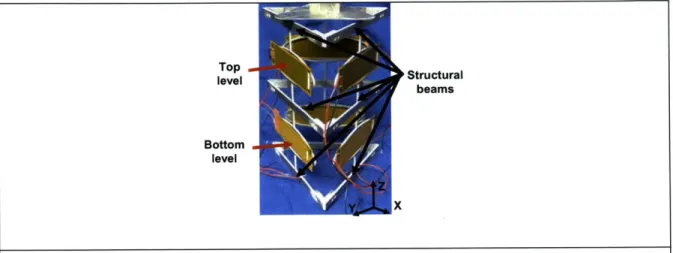
Figure 2.15 CLM manipulator with structural beams, top level, and bottom level labeled ... 5 5
Figure 2.16 CLM Manipulator Prototype with one of the three hemispherical feet for achieving three point contact identified and the ball in groove connection between the m anipulator stage and CLM ... . 56
Figure 3.1 Schematic of force and moment loads caused by a surface mounted actuator
o n a T E C A ... 5 7
Figure 3.2 Schematic of half ellipse modeled in Out-of-Plane analysis... 59
Figure 3.3 Error motions predicted by out-of-plane model vs. experimental results for A)
w /t = I and B ) w /t- 0.4 ... 6 1
Figure 3.4 Out-of-plane curl of ellipse (profile)... 62
Figure 3.5 In-plane schematic, cantilevered beam of varying radius with force applied at
tip and "no slope" constraint on free end... 63
Figure 3.6 TECA output displacement versus actuator input for A) w/t = 1 and B) w/t =
0 .4 ... 6 5
Figure 3.7 Ellipse in the Y -Z plane... 67
Figure 3.8 Straight beam approximation of ellipse... 67
Figure 3.9 A) - D) Evolution of CoMeT model of CLM manipulator... 69
Figure 3.10 A) - F) Calibration curves for the six MFC actuators used in the CLM
m an ip u lator ... 7 1
Figure 3.11 Sample Data: CoMeT (green) vs. Experiemental (Blue) ... 72
Figure 5.1 Stiffness Test fixture 1, shown from above with arc/center point indicated in re d . ... 7 9
Figure 5.2 Stiffness test fixture 2, capacitance probe locations labeled 1-5... 81
Figure 5.3 TECA for stiffness test 2... 82
Figure 5.4 A) and B) out-of-plane error motions for w/t ratios of 0.4 and 1 and C) and D) Tr for w/t ratios of 2.5 and 1. ... 83
Figure 5.5 CLM manipulator with actuators and capacitance probes labeled... 84
Figure 5.6 Manipulator test scenarios with actuator inputs indicated ... 86
Figure 5.7 Theoretical (green) versus experimental (blue) data for Z-translation test (The experimental data contains a hysteresis loop)... 88
Figure 5.8 Theoretical (green) versus experimental (blue) data for the OX and Y-translation test... . 90
Figure 5.9 Experimental versus theoretical results of translation without rotation test: A) isometric view and B) data projected onto the YZ plane... 92
Figure 5.10 Schematic of OX and Y-translation test ... 94
Figure 5.11 Measurement error in X and Y caused by misalignment 0 ... 95
Figure 8.1 MatlabTm code to calculate node positions for model of CLM manipulator. 111 Figure 9.1 CLM M anipulator analysis code ... 117
Figure 9.2 Readdat sub-function for importing data... 117
Figure 9.3 Sub-routine for analyzing the theoretical data for the CLM manipulator ... 118
List of Tables
Table 1.1 Potential Applications for the CLM... 18
Table 1.2 Old paradigm (stacked axis piezo-electric manipulators and hexapods) vs. New Paradigm (CLM manipulator: monolithic, integrated actuation and stiffness characteristics) ... . . 19
Table 2.1 Basic Mechanism Study Results: simulated performance of modules... 30
Table 2.2 Mechanism suitability... 31
Table 2.3 Actuator selection based on functional requirements [3] ... 42
Table 2.4 MFC actuator specifications ... 44
Table 2.5 Relative Suitability of Selected Materials for the Compliant Mechanism Skeleton L ayer ... . . 5 1 Table 2.6 Minimum Bend Radius for Materials Suitable for compliant mechanisms (as a function of thickness = T)... 52
Table 3.1 In-plane and out-of-plane results for w/t = 1, 0.4... 65
Table 3.2 TECA amplification CoMeT vs. In-Plane model... 68
Table 3.3 Correction factor for variations in actuator performance ... 72
Table 5.1 Slope of experimental and theoretical data and the % error for Z-translation te st ... 8 9 Table 5.2 Z-translation range (200 V) ... 89 Table 5.3 Slope of experimental and theoretical data and the % error for one side actuated ... 9 0
Table 5.4 Experimental data for error displacement in X, corresponding Y displacement,
and the angular m isalignm ent ... 91
Table 5.5 Rotation in OX, experimental, theoretical and the %error... 91
Table 5.6 Slope of experimental and theoretical data and the % error for one side actuated ... 9 3 Table 5.7 Rotation in OX, experimental, theoretical and the %error... 93
Table 5.8 Contribution to total error of each of the four primary sources of error... 97
Table 5.9 Steps to m itigate error... . 98
Table 6.1 Functional requirements versus performance of the CLM manipulator... 101
Table 6.2 Tested performance of CLM manipulator ... 105
Chapter
1
Introduction
The purpose of this research was to investigate a new method and a new practice of engineering low-cost, actuatable mechanisms. Traditional actuated mechanisms consist of discrete functional components, for instance actuators, links, joints, etc... which must be individually manufactured and assembled. The engineering, fabrication and maintenance costs associated with these systems are high. In order to keep costs low, standard components are often used. This "cookie cutter" method constrains the design, thereby leading to unfavorable trade-offs.
The central thesis of this work is that these limitations may be overcome by changing the way we perceive, design and fabricate actuated mechanisms. This work investigates the theory and practice which are needed to lay a foundation for the design of actuated mechanisms that consist of discrete functional sheets rather than discrete functional components. The various requirements of traditional, functional components is embodied in sheets, or layers, of material which may be bonded together to form an actuatable mechanism. Figure 1.1 A shows a representation of the compliant layered mechanism, CLM, concept. A CLM might consist of the following layers:
1. Skeleton layer - Provides both structural elements and compliant amplifier mechanisms. Fabricated from a single sheet of material with compliant mechanisms incorporated to provide motion guidance and amplification of actuator motions.
2. Actuator layer - Force and/or displacement sources with substantially planar geometry are either incorporated into a sheet or formed from a sheet. This layer attaches to the skeleton layer in select spots which enable the actuators to affect a change upon the skeleton layer.
Circuitry Polymer Film Actuator Metal Skeleton Compliant Layered Mechanism
processes. The electronics may then attach to the skeleton or actuator structure layer.
4. Sensors, etc... - Other functional layers may be added to satisfy the needs of specific applications.
7
(A) CLM concept (B) Hybrid CLM 5 axis
manipulator
Figure 1.1 Compliant Layered Mechanism concept and prototype
Compared to traditional actuated mechanisms, CLMs hold the potential to have:
" Lower cost: The use of parallel assembly and fabrication processes. This would reduce the costs associated with the "over use" of serial processes. In addition, the parallel processes could be used to make the layers in bulk rolls, thereby enabling cost
savings due to volume.
" Improved reliability - Parallel fabrication and assembly processes reduce the number of individual components and therefore the interfaces between them. As these
goo--interfaces are prime locations for failure to occur, the likelihood of failure for these mechanisms should be smaller.
" Improved functional customization - Parallel processes, in combination with certain serial processes may be used to make customizable layers that permit engineers to design devices which may be scaled for different geometric size, or modified to achieve greater functional flexibility.
" Improved geometric customization -If the layers could be manufactured in bulk rolls,
then the rolls could be cut to desired lengths and shapes. The assembled layers (e.g. bonded) may be sized according to specifications and then formed or folded into a desired geometry.
The CLM concept departs significantly from the traditional actuated mechanism. The technology required to make and integrate some of the desired layers is either non-existent or not well understood. The first step in generating the supporting technologies is to understand the requirements and constraints they will be used to satisfy. As such, it was deemed necessary to conduct a preliminary study in which a hybrid CLM prototype was fabricated and studied. Here, hybrid indicates that the prototype was to incorporate aspects of traditional mechanisms which closely paralleled the technologies which could be used in future CLM designs. The hybrid design also makes use of serial processes to provide components which emulate those which could be fabricated by parallel processes. Through this work, a hybrid CLM prototype would be engineered and then used as a basis to generate performance models and understand the challenges in integrating layers for the 1st generation of CLMs. Figure 1. B shows a picture of the
1.1 Motivation
This work was motivated by the need to have low-cost, actuatable flexure mechanisms for precision manipulation and robotics applications. In general, most flexure-based precision manipulators use a combination of piezo-electric actuators and flexures for motion guidance and displacement amplification. Figure 1.2 shows a common compliant amplifier-piezo actuator combination.
Mechanism Output
ctuator Input
Z X
Figure 1.2 Schematic of commercial piezo-actuator with compliant amplifier
The traditional means of building a flexure-based manipulator are based upon the assembly of many discrete components. This method places limits on manipulators as the components must be (1) individually fabricated and (2) precisely assembled. These discrete components limit the way they may be combined to form an actuatable mechanism. Due to the preceding reasons, these devices are costly and cannot be customized. The aim of this work is to generate a new concept for making flexure-based compliant manipulators from layers with integrated functional components. The functional components are arranged in arrays which can be bonded and then formed and folded to produce a topologically complex mechanism-actuator-electronic system. Numerous mechanisms could be produced from a CLM sheet. Several potential applications are listed in Table 1.1.
Table 1.1 Potential Applications for the CLM
1 Precision manipulation (nm resolution) for Fiber Optic alignment
2 Precision manipulation providing alignment during the assembly of Micro-Electro-Mechanical Systems (MEMS)
3 Morphing structures such as the Smart Wing under development by NASA and DARPA [1]
4 Energy transducing and damping mechanisms
This research has focused on generating the theoretical and practical knowledge required to engineer a, hybrid CLM prototype, which may be used as a 5 axis, Nanomanipulator. The work summarized in this thesis is a first step in examining the theory and practice of choosing the structure, compliant elements, and actuation sources for the next generation of CLM prototypes.
Table 1.2 lists some of the key characteristics/issues of the new design which were addressed by this work and contrasts them with the key characteristics of the traditional actuated mechanism paradigm.
Table 1.2 Old paradigm (stacked axis piezo-electric manipulators and hexapods) vs. New Paradigm (CLM manipulator: monolithic, integrated actuation and stiffness characteristics)
Old Paradigm: Stacked New Paradigm: CLM
Axis Manipulators and Manipulator
Hexapods
Applications each device custom built Multiple devices possible from same CLM
Cost Greater than $10,000 Less than $10,000
Range 100's Im Prototype 300 pm
Future versions greater than 1mm
Resolution 10's nm Piezo Based 10's nm
Degrees of Freedom Hexapod: 6 axis Prototype: 5 axis
1.2 Research purpose, scope and summary of results
This research is focused on answering the following questions:" Forming and folding of the layered assemblies necessitates the use of thin structural layers. What are the implications of thin structural layers in terms of performance and integration?
" What materials are best to use to satisfy the competing constraints of structural formability and structural compliance (for long-range flexure operation)?
" Which actuators technologies are best suited for CLM fabrication and operation?
" How might the kinematics of the integrated CLM be modeled?
" What practical and engineering issues must be addressed in future versions of the CLM to enable practical use?
The solutions/answers to these questions were tested through the process of design, fabrication, testing and characterization of a hybrid CLM prototype. Parametric design tools were generated to assist in synthesis, design selection, and optimization of compliant amplification mechanisms used in the skeleton layer. To establish the feasibility of the CLM concept, three primary objectives were to be accomplished:
1. Design and optimize the mechanism skeleton layer 2. Select and integrate flexible actuators
3. Build and test a functional prototype
To achieve the desired functionality of the CLM, it was necessary to generate and verify models for a structural component which is likely to become ubiquitous in structural layers. Formability requires a thin structural layer, therefore it is likely that Thin
Elliptical Compliant Amplifier mechanisms (TECAs) will be used in future CLMs. Figure 1.3 shows an example of a TECA.
TECA1L111
Actuator
a-rc
Y1:
Figure 1.3 Thin Elliptical Compliant Amplifier (TECA)
Available actuator technologies were researched and a planar, flexible actuator composed of a piezo-electric composite, the Micro Fiber Composite (MFC) actuator was selected as most promising. Lastly, research into the best suited material of construction for the skeleton layer was conducted. Aluminum 7075-T651 was used in the CLM manipulator due to its ability to satisfy formability and flexure-based design criteria. These models and the complimentary experiments will be discussed in subsequent sections. The following sections summarize the work on various aspects of the problem.
1.2.1 Objective
1
- Design and optimization: mechanism layer
The design of the mechanism layer centered on three areas:1. Design a compliant amplification mechanism
2. Integrate the compliant amplifier mechanism into an array
3. Configure the array to provide the structure, stiffness, and actuated degrees of freedom required for the prototype mechanism.
A comparative analysis of three amplification mechanisms was conducted. For reasons explained later, a compliant elliptical amplification mechanism was selected for use in the CLM. A study of the error motions from manufacturing tolerances, assembly misalignment, and surface mounting the actuators, was conducted and engineering models which describe them were verified experimentally. The integration of the
compliant amplifier mechanism into an array required consideration of how the various arrayed components, called cells, would interact in the final mechanism. The component shown in Figure 1.3 would be a cell which is arrayed as shown in Figure 1.lA. Similarly, the final design and dimensioning of the mechanism layer required consideration of the desired stiffness characteristics of the manipulator.
1.2.2 Objective 2 - Flexible actuator: selection/implementation
The CLM was made possible by advancements in actuator technology which enable flexible actuators capable of fine resolution (nm) and high force actuation. Research into available actuator technologies was conducted and a commercially available actuator was selected for use in the CLM prototype. A discussion of the actuator technologies which were considered and the actuator of choice are presented.
1.2.3 Objective 3 - Prototype manipulator
A 5-axis manipulator was modeled, designed, and constructed using hybrid CLM technology. The prototype, shown in Figure 1.1B, was formed from a single structural sheet of CLM material consisting of six actuator/amplifier mechanism units, referred to herein as cells, arranged in a two by three array. The array of mechanism cells were cut from a single, two dimensional sheet of material. By actuating the six cells in combination, 5-axis motion was achieved. A series of parametric models were developed to describe the kinematic performance of the CLM at the cellular level and at the mechanism level.
1.3 Parametric engineering model
Parametric models were generated to describe the performance of the thin elliptical compliant amplifier (TECA) cells and the manipulator prototype. Models were constructed to describe the in-plane and out-of-plane motion of the TECA in response to an actuator input at the surface of the device. The two models were based on linear beam bending theory [4]. The derivation and final models are presented in detail in Chapter 3.
1.4 Thesis organization
Chapter 2 provides detailed coverage of the conceptual design of the hybrid CLM prototype, including the design choices/process and the reasoning which led to these choices. Chapter 3 describes the models and parametric design tools developed to predict the performance of the TECA and the prototype manipulator. Chapter 4 describes the fabrication of the CLM. Chapter 5 describes the experiments used to improve and verify the models of the TECA and CLM. Chapter 6 summarizes the results of the research effort, draws conclusions about the models and prototype devices, makes recommendations for future work, and summarizes the contribution and potential impact of this work.
Chapter
2 Design
The investigation of the Compliant Layered Mechanisms (CLM) encompassed four main areas: (1) mechanism design, (2) actuator selection and characterization, (3) circuitry design, and (4) integration of the three building blocks into a layered device. The eventual goal was to develop a skeleton with actuators and circuitry applied to it. The result was to be a sheet of engineering material with integrated actuation. The sheet would then be formed and/or folded into a mechanism. The actuator selected for use in the CLM is a commercially available, flexible actuator, and the circuitry is designed to allow for the forming and folding of the CLM into a useful device.
2.1 Skeleton issues
In this chapter we concentrate on the design issues surrounding the skeleton. Each actuator was integrated into a compliant mechanism to provide amplification of the actuator displacement and guidance of the motion. Each of these actuator/compliant mechanism pairs represents a "cell." The skeleton contained an array of cells linked together by structural elements. The skeleton provided both compliant mechanisms and structural components necessary for the CLM manipulator. The key issues in designing the skeleton were:
1. The range of the final device was dependent on the transmission ratio (amplification) of the cells. While no minimum transmission ratio was pre-determined, it was understood that it was desirable to achieve the maximum amplification possible without sacrificing the stability of the device.
2. The structural elements of the skeleton were needed to link the cells together and provide a rigid support structure for the manipulator. These structural elements provided rigid members and stationary ground locations for anchoring the
locations were also important in achieving the maximum transmission ratio in the compliant mechanisms. In much the same way a lever requires a stationary fulcrum, a number of conventional compliant amplifiers require ground points (e.g. chevron beam, compliant lever). Kota [10] achieved large amplification (48x) by nesting multiple chevron beam sets in a single amplifier, however, this design required discontinuous ground elements centrally located in the mechanism. The 2D construction of the CLM placed practical limitation on the location and architecture of ground and structural components in the skeleton.
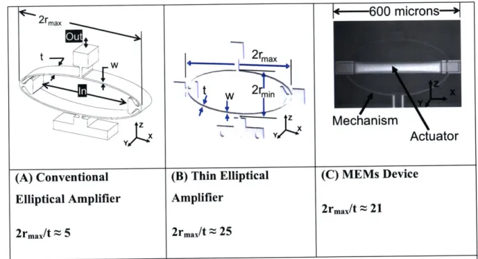
3. The most significant issue was the requirement that the mechanisms be thin enough to be formed and folded into a three dimensional device using sheet metal forming operations. Here, "thin" is defined as any device whose in-plane dimensions are at least twenty times that of the sheet thickness. Conventional compliant mechanism amplifiers have in-plane to thickness ratios of three to ten. Figure 2.1 shows conventional, thin, and MEMS versions of the elliptical amplification mechanism. 4. The final significant design issue was the minimization of spring energy stored by the
mechanism. Minimizing the stored energy would help to maximize the efficiency and transmission ratio of the mechanism.
600 microns-+I 2rmax t w 2rmi
ty
*
Tv-~LT~ykx 2 rmax tw _77 -LL ~ )x(A) Conventional (B) Thin Elliptical (C) MEMs Device Elliptical Amplifier Amplifier
2rmax/t 21
2rmax/t 5 2rmax/t 25
Figure 2.1 A) Conventional ellipse vs. B) thin and C) MEMS version of the TECA
2.2 Compliant mechanism design
Compliant mechanism functional requirements:1. Amplify actuator motion (maximum transmission ratio), overall range of manipulator needed to be on the order of hundreds of microns to ones of millimeters.
2. Guidance of actuator motion
3. Anchor points for connecting the actuators to the skeleton 4. Thin mechanism
The skeleton consisted of an array of compliant "cell" mechanisms with the above functional requirements. Conceptually, the goal was to have an array of mechanisms cut
Mechanism
(A) Order of the layers in the CLM (B) Tubular metal skeleton
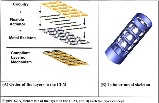
Figure 2.2 A) Schematic of the layers in the CLM, and B) skeleton layer concept
2.2.1 Basic mechanism modules: Candidate cell mechanisms
A literature search was conducted to identify a number of promising cell-like compliant mechanisms. Howell [8] and Smith [9] both cover compliant lever mechanisms, with emphasis on designing the flexure hinge for the pivot. Frecker [7] and Kota [10] have developed variations of the chevron beam compliant mechanisms. Much like the lever, pulley, and screw are ubiquitous modules used to achieve mechanical advantage in traditional mechanics. A corollary exists in compliant mechanisms where the compliant lever, chevron beam, the diamond, and the ellipse are the main modules used to generate mechanical advantage or amplification of displacement. The diamond is a symmetrical implementation of two chevron beams. Figure 2.3 below shows the three basic mechanism modules identified for further consideration: the lever, ellipse, and diamond. Having identified promising modules, the next step is to use quantitative analyses to determine which are best suited for use in CLM technology.
Circuitry Flexible Actuator Metal Skeleton --Compliant Layered Mechanism
out
r
W
t
Out
rm in rm aj r
In
Out
(A) Lever (B) Ellipse (C) Diamond
(two chevron beams)
Figure 2.3 Three Basic Mechanisms Studied (lever, diamond, ellipse)
2.2.2 Finite element analysis study of basic mechanism modules
The characteristic dimensions of the three basic mechanisms, major and minor radius, are shown in Figure 2.3. Equation ( 2-1 ) gives an approximation for the transmission ratio
of each device as a function of the characteristic dimensions.
r . Tr ~ 'maj
rmin
Transmission ratio (Tr) (2-1)
A Finite Element Analysis (FEA) study was conducted to evaluate the mechanisms based on three characteristics:
1. Transmission ratio (Tr) - amplification 2. Mechanical efficiency (i)
3. Suitability for implementation in a cellular array
The mechanical efficiency of the basic modules gives a measure of the energy stored in the compliance of the modules and was calculated using Equation ( 2-2 ).
F xS,,
Suitability was judged on:
* Cellular implementation
* Symmetry (generally improves stability and ease of manufacture) " Range
* Scalability
* Customizability (amplification, stiffness, etc.)
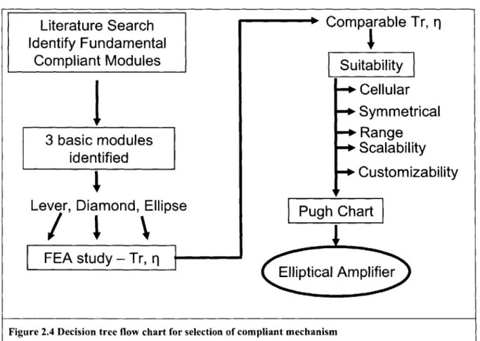
Based on these characteristics, the decision tree shown in Figure 2.4 was used to select the compliant module used in the CLM.
Literature Search
Identify Fundamental
Compliant Modules
3 basic modules
identified
Lever, Diamond, Ellipse
FEA study - Tr, r
-Comparable Tr, q
Suitability
Cellular
Symmetrical
Range
Scalability
Customizability
Pugh Chart
Elliptical Amplifier
Figure 2.4 Decision tree flow chart for selection of compliant mechanism
An FEA study was conducted using CosmosWorksTm and CoMeT . A maximum size envelope of four inches by four inches was established to ensure a fair comparison of kinematic characteristics of the modules. FEA was used to generate data that was
subsequently used to model the relationships between Tr, 17, material properties, and module dimensions. Equations ( 2-1 )
, ( 2-2 ), and Figure 2.3 show the relationship between the dimensions of the modules and their respective Tr and q.
In the simulations used to study Tr, an input force was applied to each mechanism and the corresponding input and output displacements were measured. The results of the
study are shown in Table 2.1.
Table 2.1 Basic Mechanism Study Results: simulated performance of modules
Lever Ellipse Diamond
Tr 2.4 - 20* 2.2-6.8 2.1-6.5
33%-45% 23%-40% 21%-43%
*Note: The high end transmission ratio for the lever mechanism, 20, was achieved by applying the input force so close to the flexure hinge pivot that making an actual device would be impractical.
While in theory a large ratio of major radius to minor radius may be possible, the module's kinematics become unstable at large ratios. For the ellipse and the diamond, the large major to minor diameter ratios made the modules sensitive to small forces applied at the output. These forces would result in a reversing of the output displacement direction. It is difficult to generalize and provide a metric for determining the exact value at which instability occurs because this value depends on the loads applied. Additionally, it will likely be impractical to apply an actuator to devices with large (over five) major to minor diameter ratios. Based on experience gained during simulations, ratios greater than 5:1 were avoided. More work will be required in the future to define a more accurate limit.
The mechanical efficiency was computed by comparing input energy to output energy as shown in Equation ( 2-2 ). The stored strain energy, essentially a loss, depends on the module dimensions. In the case of the lever and diamond modules, the flexure hinges had the greatest impact on efficiency. The ellipse module stored strain energy in the elliptical flexure beams.
Based on the results of the basic mechanism study, it was determined that for a given size, each of the three basic mechanisms were capable of achieving comparable transmission ratios and with comparable efficiency levels. The results, summarized in Table 2.1, show no clear winner as of yet.
The mechanisms were next evaluated based on ease of implementation in a cellular array, symmetry, range, scalability, and customizability of key stiffness and amplification characteristics. Customizability refers to the range of transmission ratios and stiffness characteristics a module can be tailored to provide. The range of the device differs from the transmission ratio in that range refers to the displacement the module can tolerate before yield. The symmetry of the device was important for its impact on device sensitivity to thermal errors, parasitic motions, and errors from manufacturing tolerances. Table 2.2 shows a qualitative assessment of how each module compared for suitability.
Table 2.2 Mechanism suitability
Suitability Lever Diamond Ellipse
Cellular 0 +1 +1
Symmetry 0 +1 +1
Range 0 0 +1
Scalability 0 0 0
Total 0 +2 +3
The diamond and the ellipse offer clear advantages over the lever configuration in terms of symmetry and how readily they could be incorporated into a cellular array. The range of the diamond is limited when compared to the ellipse due to stress concentrations in the flexure hinges. A preview of the final ellipse design is shown in Figure 2.5. Figure 2.5 indicates features which were necessary to provide interfaces for the actuator and displacement sensors (capacitance probes).
Capacitance Probe Targets
2.2.3 Detailed design of the TECA
2.2.3.1 Error sensitivity
The force applied to the TECA by an actuator has the potential to generate both in-plane and out-of-plane components. The in-plane component is the desired input force acting along rma]. The out-of-plane component of force, normal to the XZ plane as defined in Figure 2.6, is an error force with the potential to cause undesired motions of the TECA. The sensitivity of "thin" compliant amplification mechanisms to error forces was not well understood. Figure 2.6A shows the actuator mounted to the TECA.
In.Pane t
*TECA- Orce Co 0ator
Actuator Force
\lnZOut-Of-Plane Actuator
/
CX Force Component X
Actuator Force Y Out-of-plane
10x
X Actuator Force
TECA-y Cur XI N
TECA Twist
(A) Surface mount actuator causing (B) Actuator misalignment causing out-moment load of-plane force component
Figure 2.6 Out-of-plane forces and the resulting error motions
There are two potential sources of out-of-plane forces caused by the assembly of the actuator to the TECA: 1) a moment applied to the skeleton layer if the actuator is attached to only one side of the ellipse and 2) mounting errors or errors in manufacturing causing an out-of-plane component of the actuator force. This is illustrated in Figure 2.6. The figure shows the error causing forces, moment, and the resulting out-of-plane deflection (curl and twist) of the ellipse. Two important questions needed to be answered:
1. Would the out-of-plane motion result in a loss of transmission ratio?
2. To what extent could the out-of-plane errors be minimized?
FEA and a non-dimensional study were used to investigate these questions. At the time the simulation was conducted, the actuator used in the CLM had not been selected and it was not clear which of the error forces would have the greatest impact. After selecting
the actuator, it became clear that error forces causing curl were of primary concern in the CLM. Errors due to twist have been left for future study. To fully answer the questions, it was necessary to build a model to more exactly represent these errors as described in Chapters 3.
The study provided insight into the mechanics of the elliptical amplifier and a number of trends related to the performance of the ellipse when subjected to out-of-plane forces. The study is presented here because of the important role it played in gaining an understanding of the TECA and the impact it had on determining the direction of the later work. The questions will be revisited at the end of this section along with a preview of the results of the model of the curl errors.
2.2.3.2 FEA and non-dimensional simulation
The simulation considered ellipse behavior when subjected to out-of-plane normal forces caused by actuator misalignment of 5 to 10 degrees. The relationship between in-plane and out-of-plane stiffness (Kinplane and Kout-opplane), and the transmission ratio efficiency
(qT.) was of greatest interest. Transmission ratio efficiency was calculated using Equation ( 2-3 ).
7 T Tr-"ih out-of-plane forces Transmission ratio efficiency (IT.) (2-3) Tr
Fout
ra
maj
7Actuator
Force
2
Figure 2.7 Characteristic non-dimensional parameters (t/w, r,.ar.in, Fi,/F,,,)
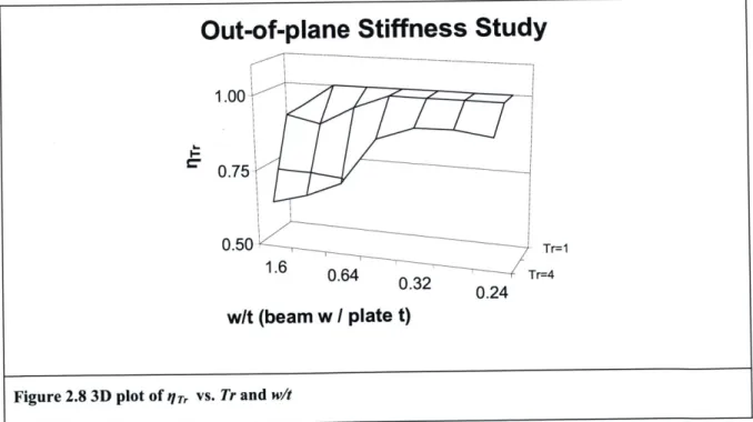
Figure 2.8 shows the results of FEA simulations used to determine /, for varying values of w/t ratio and Tr.
Out-of-plane Stiffness Study
1.00
0.75
0.50 Tr=1
1.6 0.64 0.32 0.24 Tr=4
w/t (beam w / plate t)
Figure 2.8 3D plot of I7T vs. Tr and wit
Several trends were identified from the data:
1.Out-of-plane forces resulting in device twist had the potential to cause a decrease in /,r. 2.The larger the Tr, the larger the impact of out-of-plane forces on qr/
3.The slope for the data for Tr equals 4 was greatest near w/t equal to 0.5. This indicated a transition point, where, for values of w/t greater than 0.5, there was a rapid decrease in qT.. This transition point is of interest as it shows a high sensitivity of qT. for Tr equal to 4 and w/t equal to 0.5.
4.The results indicated a relationship between out-of-plane forces and qTr. To understand the relationship, further investigation was needed.
The results were consistent with our expectations based on mechanics of materials. As the transmission ratio increased, the beam length subjected to the out-of-plane forces increased (rnqj) compared to the beam length subjected to in-plane force (rm,,i). It was not surprising then that as transmission ratio increased the sensitivity to out-of-plane forces also increased.
Trend 3 was also consistent with an intuitive investigation of the device. As described by Equations ( 2-4 ) through ( 2-17 ), at the transition point where Tr equals 4 and w/t equals 0.5, the in-plane and out-of-plane stiffness are approximately equal. At w/t ratios greater than 0.5, the out-of-plane stiffness is less than the in-plane stiffness and, conversely, for
w/t ratios less than 0.5, the out-of-plane stiffness is greater than the in-plane stiffness.
Thus, when the out-of-plane stiffness is less than the in-plane stiffness (w/t greater than 0.5) the out-of-plane deflection is large causing a significant impact on the nTr and the high sensitivity observed in the figure as described by Trend 3.
The following analysis was used to provide a first order approximation of the in-plane to out-of-plane stiffness at the transition point. The analysis relies on proportionality and the scaling of stiffness with moment of inertia and radius.
The flexure beams were subjected to forces in two different axes, one in-plane along rmaj
and one normal to the plane, acting on the ellipse at rna]. The area moment of inertia for the in-plane force is proportional to the thickness times the width cubed (tw3) while the
moment of inertia for the out-of-plane forces is proportional to the reverse of the terms
w/t ratio was varied from 1 to 0.5. This caused the ratio of in-plane moment of inertia to out-of-plane moment of inertia to increase by a factor of four.
in-plane OC t W3 ( 2-4 ) Iout-of-plane OC W X t3 (2-5) 'in-plane t x w3 w2 Iout-of-plane Wxt t 2 ( 2-6 ) Iin-plane i for w_ -Iout-o-plane t (2-7) Ii" p""" ~0.25 for w- = 0.5 Iout-o -plane t ( 2-8 )
For a transmission ratio of four, the beam length subjected to an out-of-plane bending moment was four times that of the length of beam subjected to an in-plane bending moment (rna vs. rnin). Based on this approximation for the area moment of inertia and the length of the beams (rnaj, rnin) it is possible to understand how the in-plane and out-of plane stiffness (Kin-piane, Kout-of-plane) scale with I and r. This relationship is determined from the relationship between force (F), stiffness (K), displacement (z), bending moment (M), area moment of inertia (1), and beam length (rnaj, rnin) as shown in Equations ( 2-9) through ( 2-17).
F=Kxz (2-9)
z 0C Neglecting material properties and double integration
p (2-10)
M=Fxr (2-11)
K or- I substitute ( 2-10 ) and ( 2-11 ) into ( 2-9
)
n I/.- plane Kin-plan r (2-13) -ow -of-plane K01,0 _, O rnal (2-14) rmn = 0.25 for Tr =4 rni, (2-15) Kin-plane I_ r.,,
Ko,_ftt anf e I-i ',1,_ -pne r.mi ( 2-16 )
Ki"-p""n oc 4 x 0.25 = 1 substitute ( 2-8 ) and 2-15 (for 0.5)
K(,_ (-)l(fo t (2-17)
For error forces normal to the ellipse, caused by actuator misalignment, there is a relationship between qrr and the ratio of in-plane stiffness to out-of-plane stiffness. This was not the case for error motions (curl) caused by mounting the actuator on one side of the ellipse. The model will be shown in detail in Chapter 3. The amount of out-of-plane displacement was related to the ratio of in-plane to out-of-plane stiffness as in the model of the twist, but these error motions did not impact the Tr in the model for curl.
The answer to the two questions will be shown to be 1) no - out-of-plane curl does not have an impact on transmission ratio, and 2) yes - the magnitude of the out-of-plane curl can be controlled by the designer by varying the ratio of in-plane to out-of-plane stiffness.
2.2.3.3 Flexure decoupling of cells
Functional requirements:
1. Decouple cells from skeleton structure 2. Maintain stiffness of the manipulator
force and moment on the other two sides. We desire to minimize them. We also wish to prevent such loads and displacements from causing other actuators to undergo compression (e.g. go slack). This is important as the actuators are flexible and therefore only capable of generating "pull" forces.
YJZ
(A) CLM manipulator prototype (B) gray - non-deformed geometry, blue - deformed
Figure 2.9 A) CLM manipulator prototype, B) Displacement caused by actuating one side of the manipulator
Figure 2.10 shows the final design of the module. The individual cells were linked to the structural elements of the mechanism layer by flexure beams. The flexure beams helped to isolate ellipses from moment and out-of-plane forces. At the same time, it was necessary to maintain the integrity (stiffness) of the device as a whole. Further consideration of the flexure beams is needed to optimize the design in future versions of the CLM. For the prototype, the flexures between the cell (ellipse) and structure were designed to have bending stiffness of the same order as the cell's beams. This was done to ensure that the stiffness of the manipulator was determined by the cells and not the flexures linking the cells to the structure. The matched stiffness provided the maximum decoupling of the cells from the structure possible without significantly decreasing the stiffness of the manipulator.
1 major. Dminort
... Z
Flexure
beams
CX
Figure 2.10 Final module: elliptical cell
The elliptical amplification mechanism had major and minor diameters of 4.5 and 1.5 inches respectively (as shown in the figure) and a Tr of approximately three. These sizes were set in-part on the constraints placed by the size of the available actuators. This will be discussed in detail in Section 2.3.
2.3 Actuator selection
The functional requirements for the CLM actuator are as follows:
" Survivability -Tolerant of handling and capable of surviving forming process " Force - Must generate 10's to 100's of N
" Flexible - to conform to non-planar skeleton geometries " Fine resolution - Approximately 1 nm
* Low power - High power loss actuators cause thermal errors
* Low aspect ratio - Sheet-like actuators were desired so that the actuators could be applied as a "layer" in the CLM
" Low cost - Future devices may require 10's to 100's of actuators. Cost of these components must be kept low.
2.3.1 Actuator technology review
1. Piezo-electric
2. Shape memory alloys (SMA) 3. Electrostrictive polymer 4. Magnetostrictive
5. Electrostatic
Table 2.3 compares actuator characteristics and functional requirements. The Macro Fiber Composite (MFC) [11] actuator was the actuator used in the CLM. The MFC offers the force and resolution of piezo-electric actuators in a package that is flexible. A detailed discussion of each of the actuator technologies follows the table.
Table 2.3 Actuator selection based on functional requirements 131
Electro- Macro
strictive Fiber
Functional Piezo- SMA Polymer Magneto-
Electro- Composite
Requirements Electric Strictive static
Survivability 0 +1 +1 +1 +1 +1 Force 0 0 -1 0 -1 0 Flexible 0 +1 +1 -1 0 +1 Nanometer 0 -1 -1 0 -1 0 Resolution Low Power 0 -1 -1 -1 -1 0 Low Aspect 0 +1 +1 -1 0 +1 Ratio
Low Cost 0 0 n/a* 0 0 +1
Total 0 +1 0 -2 -2 +4
*Electrostrictive Polymer actuators are not readily available commercially ** The MFC actuators used in the CLM cost ~$130 but require a high voltage (>200 Volts) to achieve full range.
(low power) power supply
2.3.1.1 Magnetostrictive actuators
The magnetostrictive actuators relied on magnets and large electric coils. Implementing "large coils" within the layers was impractical. Also, the coils generate heat [3]. Thermal errors posed a significant risk to achieving the repeatability and resolution required of the CLM.
2.3.1.2 Electrostatic actuators
Electrostatic actuators rely on charging electrodes with high voltage (>800volts) and the best of the actuators are typically capable of 80ptm resolution [3]. The high voltage and the poor resolution of the device prevented the actuators from being implemented in the CLM. Power supplies capable of generating such high voltage are cost prohibitive and the CLM required high resolution (10's of nm).
2.3.1.3 Shape memory alloys
Shape memory alloys (SMAs) are attractive in terms of stress and strain capabilities (>200 MN/m3 stress, and >5% strain) [3]. However, SMAs rely on passing current through the actuator and generating thermal disturbances. Additionally, SMAs are only readily available as binary actuators and the CLM required an analog actuator [3].
2.3.1.4 Electrostrictive polymers
Electrostrictive polymers offered an advantage over Piezo-electric based actuators in that they may be configured to provide a tension force (negative strain). A number of issues with these actuators posed significant design challenges.
1. Poor stability and high hysteresis due to creep of the polymer
2. Electrostrictive polymers require an electrolytic solution; bath or a painted on gel to function [3]. This increased complexity in implementation within the device [3]. Also, the CLM manipulator might be used in a clean room environment (MEMS fabrication or Fiberoptics positioning). Introducing a liquid bath or gel to the clean room would be undesirable.
3. Electrostrictive polymer actuators were not commercially available.
2.3.1.5 Piezo composite actuator
The Macro Fiber Composite (MFC) actuator, commercially available from Smart Materials Corp [11, 12], has good force, power, and resolution characteristics. These actuators are packaged in a flexible, tough, low cost composite. The MFC actuator is
constructed from piezo-electric ceramic incorporated into layers of polyimide film with integrated electrodes. The actuators may be used to generate negative strain. Details on the actuator performance are given in [11] and additional information is available from Smart Materials Corp [12]. Table 2.4 indicates key specifications of the MFC actuator.
Table 2.4 MFC actuator specifications
Specification MFC Actuator (part #: M8528 P2)
Overall dimensions (mm) 106 x 31
Active area (mm) 85 x 28
Maximum voltage (V) -60 to 360 V
Maximum tensile strain 4500 ppm
Tested range (for 0 - 200V) microns 21 to 56
Figure 2.11 shows a picture of the MFC actuator used in the CLM.
Electrical Direction of Actuation Contacts (compressive)
YFu 2
2.4 Circuitry
Functional Requirements:
* Flat - a "layer" of the CLM
* Survivability - must endure handling and forming process
* Low Stiffness - application to mechanism layer should not noticeably impact stiffness characteristics of CLM
The circuitry in a finalized CLM device was to be applied to the actuators and skeleton as a flat sheet. This would allow the cost advantages of layered construction. Unfortunately, it was not possible to form the structural layer from one piece. The sheet was instead assembled from three separate two by one cell arrays. The final shape emulated that which would be made using a forming process. The circuitry was not applied as a layer in the CLM but instead wires were run connecting the actuators directly to the power supply. Because of this, the circuitry did not need to be formed. The wires were stress relieved to minimize impact of the wires on the manipulator stiffness. Future versions of the manipulator will incorporate flat circuitry. The necessary compliance of the circuitry depends on the range of motion of the device. The circuit needs to be compliant to move with the cell module and the CLM structure as the actuators are energized. For the prototype manipulator, future versions incorporating flat circuitry would need to tolerate up to 300 microns of deflection over approximately 12 cm. Figure 2.12 shows a picture of the assembled manipulator prototype.
Manipulator
Figure 2.12 CLM Manipulator Prototype
2.5 Integration of the skeleton layer, actuators, and circuitry
The functional requirements, issues and concerns facing integration of the mechanism and actuator layers included:" Adhesion - mounting the actuators to the modules * Minimize impact of mounting on the modules * Actuator alignment - prevent "wrinkle" * Actuator preload - prevent "slack"
2.5.1 Attaching the Actuators to the Compliant Mechanism Skeleton
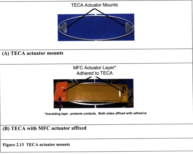
Figure 2.13 shows the connection point designed into the TECA cell, both before (A), and after (B) the actuator has been attached.Mechanism Layer
Wiring
Actuator Layer
TECA Actuator Mounts
2.5.1.1 Design of the actuator mounts
The actuator mounts were designed with two goals in mind: 1) minimize the effect of the mounts on the flexure beams of the TECA, and 2) provide an area for bonding the actuator to the module. To achieve the first goal, the actuator mounts interface to the TECA only along the major radius as shown in Figure 2.13 A.
Only the non-active area of the actuator could be bonded, where there were no piezo elements. To achieve the second goal, the actuator needed to be supported over a length normal to the direction of actuation equal to or greater than the width of the active area. If an insufficient portion of the actuator were bonded, the maximum force the actuator could generate would be reduced. This is because the outer edges of the actuator could strain without displacing the TECA. It was also important to adequately support the (A) TECA actuator mounts
MFC Actuator Layer* Adhered to TECA
*Insulating tape -protects contacts. Both sides affixed with adhesive
(B) TECA with MFC actuator affixed