Design of a Control System for a
Mobile Torrefaction Reactor
By Alejandro Garcia
Submitted to the
Department of Mechanical Engineering
in Partial Fulfillment of the Requirements for the Degree of
Bachelor of Science in Mechanical Engineering at the
Massachusetts Institute of Technology
February 2018
C2018 Massachusetts Institute of Technology. All rights reserved.
Signature of Author:
Signature redacted
Department of Mechanical Engineering January 19, 2018
Signature redacted
Certified by:
Ahmed Ghoniem Professor of Mechanical Engineering
Signature redacted
Thesis SupervisorAccepted by:.
MASSACHUSETS INSTrTUTE OF TECHNOLOGY
SEP 13 2018
Rohit Karnik Associate Professor of Mechanical Engineering Undergraduate Officer
Design of a Control System for a
Mobile Torrefaction Reactor
By
Alejandro Garcia
Submitted to the
Department of Mechanical Engineering on January 19, 2018 in Partial Fulfillment of the
Requirements for the Degree of
Bachelor of Science in Mechanical Engineering
Abstract
In MIT's Tata Center, work is being done to develop a mobile torrefaction reactor that can be used to aid those in developing countries in need of alternative sources of energy. A vital component of the reactor is developing an appropriate control system for the necessary
components. The previous method of control has proven time intensive, inaccurate, and overall inefficient. A new control method is needed to allow for effortless control of the torrefaction reactor both in the lab and on the field. The new controller would have to be compact, control multiple components simultaneously and be uncomplicated to use. The proposed solution is to utilize a microcontroller board to develop a singular interface that would provide ease of use and the ability to accurately control all of the components involved in the reactor. It would utilize a simple numeric keypad to receive inputs that would be used to control the components and a small lcd display to monitor the system. Despite not being able to build the final control system, the framework for it has been developed here and suggestions on moving forward are outlined.
Thesis Supervisor: Ahmed Ghoniem Title: Professor of Mechanical Engineering
Acknowledgements
I would like to express my deepest thanks to my thesis-supervisor, Professor Ahmed Ghoniem, as well as graduate student, Kevin Kung, for the opportunity to work on this project this past fall semester. It was a great learning experience and I just wish I had more time to continue work on it.
To all of my friends, thank you for all of your support throughout my time at MIT. It means so much to me that I was able to be surrounded by, and learn from, such amazing individuals that cared so much for me. Arman, Erik and Hugo, you guys were the first friends I made at MIT and over the years became family, thank you for always watching out for me. Amanda, Jocelyn, Katie, Lucy and Paul, you all always know how to make the best of any situation and made my last semester such a memorable one. Thank you for all the love, support and great memories.
To my family, thank you for always encouraging me to do my best and push through tough times. You have always been my source of strength. To my parents, Bertha and Filiberto, I want to dedicate my MIT degree to you. You have made sacrifices in your lives so I would have the
Table of Contents
List ... 9 List of Tables...11 1. Introduction...13 1.1 Torrefaction... 13 2. Reactor Components...14 2.1 Motor... 14 2.2 Flow Controller...15 3. Design...16 3.1 Design Requirements...16 3.2 Methods of Control...17 3.2.1 Motor Driver... 173.2.2 Remote Control of Flow Controller...18
3.3 Designing the Control System...19
3.3.1 Microcontroller... 19
3.3.2 Motor Driver Control...20
3.3.3 Controller Input... 22
3.3.4 Controller Display...23
4. Development...24
4.1 Motor Connections... 24
4.2 Flow Controller Connections... 27
4.3 Numeric Keypad Connections...28
4.4 LCD Display Connections...30
4.5 Code...30
S. Conclusions and Future W ork...31
6. Appendix... ... 33
6.1 Bison Motor... 33
6.2 Flow Controller D-Connector Pin Functions...34
6.3 Flow Controller Jumper Locations...35
6.4 Mega 2560 Rev 3 Microcontroller...36
6.5 Minarik Motor Driver...37
6.6 Numeric Keypad Matrix... 38
6.7 PW M-to-Analog Converter...38
6.8 Code...39
6.9 Housing...48
List of Figures
Figure 1: Figure 2: Figure 3: Figure 4: Figure 5: Figure 6: Figure 7: Figure 8: Figure 9: Figure 10: Figure 11: Figure 12: Figure 13: Figure 14: Figure 15: Figure 16: Figure 17: Figure 18: Figure 19: Figure 20:Iron Horse motor driver...14
Omega mass flow controller...15
Mega 2560 microcontroller board...20
Minarik motor driver...21
Numeric 12-button keypad...22
Smraza Electronics Icd display... 23
LCD display's microcontroller...23
Prototype screw shield...24
Wall plug to motor schematic... 25
Soldered PWM-to-analog converter... 26
Soldered Resistors for keypad...29
Close-up to the lcd's microcontroller...30
Bison Motor...33
Flow controller's D-connector...34
Flow controller's jumper locations...35
Mega 2560 microcontroller connections...36
Numeric keypad matrix...38
Low-pass filter circuit...38
Motor driver housing CAD model...48
List of
Tables
Table 1: Minarik motor driver connections...27
Table 2: Flow controller connections...28
Table 3: Numeric Keypad connections...29
Table 4: LCD display connections...30
Table 5: Bison motor wires...33
Table 6: Bison motor specifications...33
Table 7: Flow controller jumper configurations...35
Table 8: Mega 2560 microcontroller board specifications... 36
Table 9: Minarik motor driver connection ports...37
1. Introduction
The aim of the project presented in this thesis was to develop the framework for a control system for an existing mobile torrefaction reactor. In this section I will give a brief description of torrefaction to provide a basic understanding of the larger system. In future sections I will go over the process undergone to develop the controller starting with analyzing the components of the initial torrefaction reactor that need to be controlled and the requirements for the system. Then I will go through the design and development. Finally, I will conclude with a discussion of how I believe this project should move forward.
1.1 Torrefaction
Torrefaction is a thermochemical process that can be used to treat biomass to convert it into a high-grade solid biofuel. The process is undergone in a high temperature, low-oxygen environment where moisture and volatiles in the biomass are driven out. The end result is a charcoal-like material that can be used as an efficient source of biofuel. Torrefaction is believed to be a reliable solution to the ongoing energy crisis especially in impoverished countries. Countless of these countries dispose of unneeded biomass by incineration wasting the material that can be converted to an efficient source of fuel and proves on being extremely harmful to the environment [3].
2. Reactor Components
The torrefaction reactor I am working with contains two crucial components that need to be controlled, a motor that drives an auger which churns the biomass material and a flow controller which controls the input of oxygen into the thermochemical process. The speed of the auger and amount of oxygen inputted into the reactor could determine the end quality of the biofuel and having a system to control the components will not only provide ease of operation but a reliable form to produce high quality biofuel.
2.1 Motor
The motor utilized for the torrefaction reactor is a Bison 336 series 37 Watt permanent magnet 90V/130V brushed motor (See Appendix 6.1). The DC motor can provide up to 293 in-lbs of torque and was chosen for its high torque output which is necessary to turn the biomass-filled auger in the reactor. Previously, the DC motor's speed was adjusted via an Iron Horse GSD3 Series DC general purpose motor driver which had an exterior manual potentiometer that was utilized to adjust the speed of the motor.
Figure 1: Iron Horse motor driver that was previously used to control the speed of the motor. On the left side you can see the dial that was used to manually adjust the speed.
Despite the Iron Horse motor driver providing a form to control the speed of the motor it lacked accuracy. The speed input was taken by a manual potentiometer, as you can see in Figure 1, with the only indication of speed being a scale from 0 to 10 that is depicted on the side of the potentiometer. A controller with a more accurate input system would be beneficial for testing as well as long term use of the reactor.
2.2 Flow Controller
The torrefaction reactor requires a controlled airflow which comes from a tank of pressurized air and is managed by an Omega Engineering electronic gas mass flow controller (FMAS528A). To control the airflow the user can manually set a target value or setpoint using the potentiometer on the side of the mass flow controller. The controller can also be connected to a computer using a 15 pin D-connector which would allow for remote control of the flow using specialized software [7].
Figure 2: The image on the left is of the Omega mass
flow controller used in the system. It has a
D-connector on the left side of the device that allows for remote control of the gas flow setpoint and a potentiometer on the right side that can be used to
input the setpoint manually. The silver cylinder on
the right side is the housing for the motor that manages the opening of the control valve.
The flow controller used possesses a display, such as the one on the right side of figure 2, that provides a reading of the flow of air being inputted to the reactor. Despite being able to provide
an accurate reading of the flow into the system, the flow controller still needed a better method to input the setpoint that would be both effortless and accurate.
3. Design
In this section I will go over the design requirements that I took into account when
designing the control system then I will go through the research and thought process that went into the design for controlling each component.
3.1 Design Requirements
The goal of this project was to develop the framework for a control system that could provide effortless control of both the motor and flow controller using a singular interface. The previous method of operation of the torrefaction reactor required setting the speed of the motor and setpoint of the flow controller using seperate manual potentiometers which made it difficult for quick and accurate operation of the system. Creating a singular electronic interface would allow for quick and repeatable testing in the lab environment.
Other design requirements involved the future of the reactor and its tests in the field. The torrefaction reactor primary field testing location would be in rural farms in countries such as India and Kenya where biomass waste is abundant and alternative sources of energy are desperately needed. To be suitable for these environments the system would have to be compact so to be easily transported with the reactor, provide ease of use so the system can be operated by the locals in these areas, and have both durable and easily replaceable components.
3.2 Methods of Control
To start the design process for the control system I first looked further into the initial methods that were used to control the individual components. For the motor I researched the Iron Horse motor driver and motor drivers in general to get a better understanding of how they work. For the flow controller I looked into how mass flow controllers operate and studied the manual of the Omega flow controller to understand how it can be remotely controlled using an external signal, instead of manually setting the target value using the potentiometer.
3.2.1 Motor Driver
A DC motor's speed is determined by the voltage as well as the characteristics of the motor itself but the motor speed is directly proportional to the voltage delivered to it. This is how typical speed controllers or motor drivers operate. For smaller motors, such as 12V motors, motor drivers can easily be designed to adjust the direct voltage sent to the system but for larger motors this becomes highly inefficient if 110V has to be reduced to 60V to slow down a motor. For this reason typical motor drivers operate by sending a pulsed signal, or a Pulse Width Modulation (PWM) signal, which the motor reads by averaging out the voltage sent to it .A PWM signal sent to a motor is comparable to a motor being constantly turned on and off. The percent of the time it is on during a period is called the duty cycle, with 100% being always on. The closer the duty cycle of the PWM signal is to 100% the closer it is to the max voltage output of the system and the faster the motor will turn. Most DC motors can't differentiate from a continuous signal and a PWM signal, this method allows motor drivers to be greatly more efficient [10].
The integrated circuit in motor drivers are responsible for taking in an input signal that corresponds to the desire speed of the motor and utilizing it to create an appropriate PWM signal from the supplied voltage that will meet the needed speed. In the Iron Horse motor driver this input
signal is controlled by the manual potentiometer that came with the device, but more sophisticated motor drivers can receive an external signal in order to control the speed of the motor. These external signals can be sent from computers or similar device to provide the user with an accurate and precise form of controlling the system. The type of signal the driver receives depends on the driver itself but typically these drivers have a range for the voltage of the signal and the minimum voltage will correspond to the minimum speed of the motor and the maximum voltage signal corresponds to the maximum motor speed.
Moving forward I had to consider whether the Iron Horse motor driver was appropriate for this project or if a more sophisticated motor driver that can receive an external signal to control the motor speed would be the preferable direction to go.
3.2.2 Remote Control of Flow Controller
Mass flow controllers are used in the industrial field when accurate control of a fluid's flow is required. They operate by taking in a pressurized fluid flow which is then split with a portion being directed to a flow rate sensor. The flow rate sensor will measure the volumetric flow of the fluid but will also take into account the pressure and temperature of fluid to get an accurate reading of the true fluid flow. The sensor will then output a signal that can be amplified and read to provide a reading of the fluid's flow rate [12].
When a setpoint, is inputted into the controller the output signal of the flow rate sensor is also sent to operate the outlet control valve. In common mass flow controllers the control valve consists of a motor that operates a metal diaphragm that is used to control the size of the opening of the exit and a comparison circuit that compares the output of the flow rate sensor with the desired
The mass flow controller we are utilizing in the system possesses a D-connector that provides a port for input and output signals for the system. This port contains pins to power the device as well as output pins for the flow rate sensor and input pins for the setpoint of the control valve. The manual of the device provides the functions of the D-connector pins which will be crucial
in controlling the system (See Appendix 6.2). From the manual I am also able to see that the flow rate sensor outputs an analog signal between 0 to 5V that can be converted to provide a flow reading. The flow controller can also receive an input analog signal of 0 to 5V, or a 4 to 20 mA signal, to apply a setpoint to the control valve. In order to be capable to remotely operate the flow controller I will need to take this into consideration for the design of the control system [7].
3.3 Designing the Control System
Once further research was done on the methods of control for the components I knew it would be possible to develop a control system using a microcontroller. A microcontroller is often generalized as being a mini computer that can be specialized for a certain purpose and are very common in today's world.
3.3.1 Microcontroller
For my purposes I looked into microcontroller boards, such as those developed and made famous by Arduino, which provide an integrated circuit to make programming and connecting components to the microcontroller uncomplicated. Arduino is an open-source electronics platform that provides hardware and an accompanying software that makes prototyping with their, and similar microcontroller boards, simple. Their microcontroller boards are small, inexpensive, and can be bought or made almost anywhere in the world, so they would be ideal for my application.
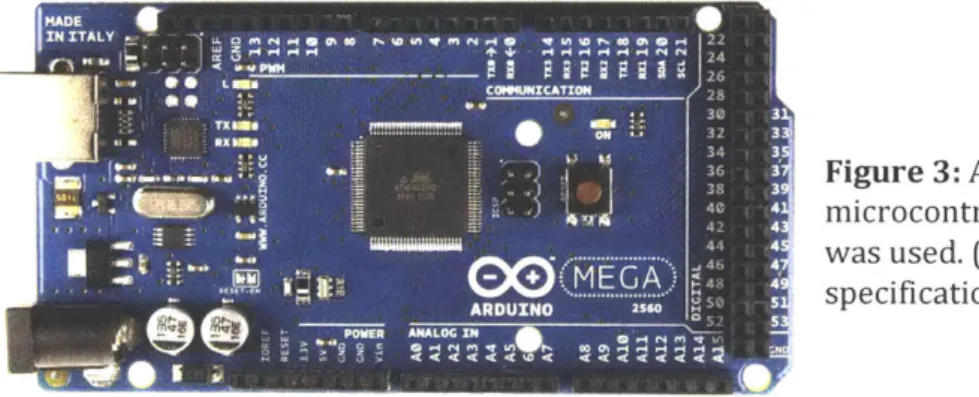
There are a wide variety of microcontroller boards that have been developed to serve a wide range of projects but after researching different boards I decided to use a Mega 2560 Rev3 board with a ATmega2560 microcontroller. My decision to proceed with the Mega 2560 was due to its wider range of capabilities when compared to other microcontroller boards, it possesses more memory and input/output pins than many of the other boards available which would allow for faster processing and space for additional components to be connected in the future if necessary.
MADE - -
--IN ITALY * 4 o .0 Pa in m r ia i at i e o 22
COMMICATION 28
Figure
3: A similar Mega 2560 microcontroller board to that whicht ... was used. (See Appendix 6.4 for board
0 ARDUXNO - 25M-specifications)
The Mega 2560 microcontroller board can take in an input voltage from 6 to 20V through its power jack and convert it to its operating voltage of 5V. This operating voltage allows the system to output signals from 0 to 5V from any of its fifty-four digital signal pins. The board can also receive 0 to 5V digital signals through these same digital pins and contains sixteen analog input pins for 0 to 5V analog signals [2].
3.3.2 Motor Driver Control
After deciding to use a microcontroller for the control system I needed to figure how to utilize it to control the motor's speed. My initial idea was to attempt to replace the manual 5K Ohms potentiometer in the Iron Horse motor driver with a digital potentiometer. A digital potentiometer,
of the motor driver which is regulated to determine the motor speed but instead of the resistance being controlled through manually turning a dial it would be controlled through a 0 to 5V digital signal from the arduino. Through searching for an adequate digital potentiometer none could be found that could handle the high voltages of the motor driver.
Next, I began to search for different motor drivers that would enable me to control the motor speed through an external signal from the microcontroller. Most motor drivers I came across through my search were able to be controlled through an external analog signal of 0 to 10V. Since this range was too high for the microcontroller's 5V max output I looked into voltage boost converter circuits to attempt to convert the 0 to 5V to the needed 0 to 1OV. The boost converters did not allow for a full 0 to 1OV range using the microcontrollers 0 to 5V range so this method was also abandoned.
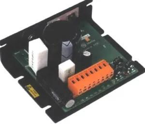
Through further research I came across a driver by Minarik Drives , the XP02-115AC-Q model DC motor driver, which possesses the capability of receiving an external analog signal of 0 to 5V. With a power range of 1/20 to 6 H P and output voltage of 0 to 130V this motor driver meets the necessary specifications to drive the motor being used. Using this motor driver it would now be possible to control the motor speed with the microcontroller.
Figure 4: The XP02-115AC-Q model DC motor driver by Minarik Drives allows for an external analog signal of 0 to 5V to be used to control the motor speed. (See Appendix 6.5 for driver specifications)
3.3.3 Controller Input
Next came the task of figuring out an adequate method of inputting the desired motor speed and flow rate setpoint into the microcontroller. The requirements for an input device were:
1. Capable of communicating with the Mega 2560 microcontroller board. 2. Small in size to keep the entire control system compact.
3. Can be easily operated by anyone. 4. Inexpensive.
5. Durable.
After researching different possible devices I decided a suitable input device to operate the system would be a numeric keypad. Numeric keypads are widely used by people all around the world for various applications therefore utilizing one for this project would allow for a familiar form of input for whoever operates the controls.
I found a 12-button keypad, as you can see in figure 5 below, that I would go on to use for the system. It is small, inexpensive, and made from plastic which is not the most durable material but provides enough protection for the inner circuitry that it should not cause any problems. The twelve buttons of the keypad are on a three by four matrix format which allows for less wires which need to be connected to the microcontroller board (See Appendix 6.6).
- Figure 5: The 12-key keypad that was used for inputting the
3.3.4 Controller Display
In order to monitor the inputted motor speed and flow rate setpoint values the controller would require some form of display. For this reason I searched for a simple Icd display that would meet the same basic requirements of the input device, be small, inexpensive, durable and able to communicate with the microcontroller board.
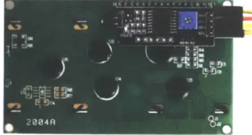
I decided to go with a lcd display by Smraza Electronics, as shown in figure 6 below. The lcd screen has the capability of displaying four lines of text with twenty characters per line. Not much considering sizes of modern lcd screens but keeping the amount of characters to a minimum allows for a smaller and less expensive screen.
Figure 6: The Icd display by Smraza Electronics. It can display four lines of text with a maximum of twenty characters per line.
This particular screen is also designed to be easily connected to microcontroller boards. As you can see in figure 7 below, this lcd screen already has a small microcontroller board attached to its back. This display comes with the microcontroller board to simplify the process of connecting it. Similar boards often require an upwards of sixteen wire connections in order for them to
communicate with a microcontroller but the microcontroller that comes with this Smraza Electronics display reduces the number to four wires.
Figure 7: The back of the lcd display with the microcontroller board shown on the top right corner.
4. Development
Once acquiring all the necessary components previously mentioned, as well as a 9V
microcontroller board power adapter to supply power to the controller, the next step was to make all the required connections from the motor driver, flow controller, numeric keypad and lcd display to the microcontroller board. To simplify this process I acquired a prototype screw shield, as seen in figure 8, for the microcontroller board which connects to the top of the board and makes wiring connections easy and also provides space for additional electronics to be soldered on.
...
fl....
.
.
a Figure 8: The prototype screwshield. It is connected on the top of the Mega Microcontroller.
4.1 Motor Connections
The first connections that needed to be made were those of the motor to the motor driver. The Bison motor possesses three connections, a red wire for the positive side of the motor
armature, a black wire for the negative side of the motor armature, and a green wire for ground. The the positive motor armature wire goes to the Al port on the motor driver, and the negative wire goes to A2. The Al port is responsible for outputting the voltage that will drive the motor and
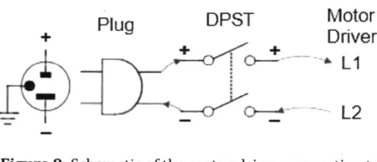
Next, the driver was connected to the wall outlet cable which will supply the AC power to the system. For this a standard NEMA 5-15 three prong plug, a double-pole single-throw (DPST) switch and 14-gauge wire were used to connect to the motor driver. The positive terminal wire on the wall plug was first connected to the positive terminal of the DPST switch and then connected to Li on the motor driver and the negative terminal wire was connected to the negative terminal of the DPST switch and then to the L2 port. At this time the ground terminal was not utilized but can be connected to the motor green ground wire for added safety.
Plug
DPST
Motor
+
PuDver
_~LI
L2
Figure 9: Schematic of the motor driver connecting to
the wall plug.
The last connections that needed to be made to control the motor were those between the motor driver and our Mega 2560 microcontroller board. The microcontroller board could only output digital PWM voltage signals and in order to control the motor speed this would first need to be converted to an analog voltage for the motor driver. To convert the PWM signals to an
appropriate analog signal a low-pass filter was made and soldered onto the prototype shield, as seen in figure 9. A low-pass filter converts a PWM signal to an appropriate voltage which
corresponds to the duty cycle of the PWM signal. This does not produce a perfect analog signal as the resulting signal usually has a ripple in the output voltage but this can be tuned with the selected resistor and capacitors [1].
S 0 o o o o o o r -C EliMotor Driver 4%,.
S2
(: (: 0 (> 0 0 () 0 Mega S 0 0 4OO
O(
bPins
1312-00C 0 U
C
a.. Flow ControllerSP d 0 1 e 3 a o Pin 8
Figure 10: In the picture in the left are the two soldered low-pass filters that were used as PWM-to-analog converters. one for the motor controller and the other for the flow controller. On the right is the schematic of soldered circuit.
The filter that was made used a 3.3 kilo Ohms resistor and a 0.1 microFarads capacitor. The size of these components determine the ripple of the resulting analog signal's voltage as well the settling time for the voltage. These values can be calculated with specific equations but for these purposes an online calculator was used [8].
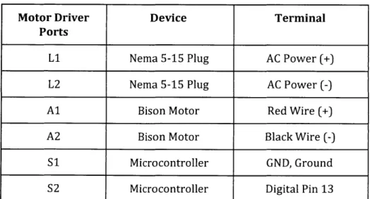
Now with the PWM-to-analog converter in place we could now connect the microcontroller to the motor driver. We first connected the microcontroller's digital pin 13 to the the low-pass filter, which would act as the input voltage of the circuit, and then connected a wire from the output voltage of the filter to the S2, or signal input, port on motor driver. The S1, or signal common, port on the motor driver was then connected to one of the microcontroller's ground pins as (See figure
Motor Driver Device Terminal Ports
Li Nema 5-15 Plug AC Power (+)
L2 Nema 5-15 Plug AC Power (-)
Al Bison Motor Red Wire (+)
A2 Bison Motor Black Wire (-)
S1 Microcontroller GND, Ground
S2 Microcontroller Digital Pin 13
Table 1: The table above shows the devices, and the respective terminal, the motor driver ports are connected to. Note: Signal converter
connection between S2 and digital pin 13.
4.2 Flow Controller Connections
The next component that was to be connected was the mass flow controller. For the flow controller we not only wanted to remotely control it with an external signal from the
microcontroller board but also have the board take in the output analog signal from the flow rate sensor to produce a flow rate reading. The flow controller we have been using already comes with a preinstalled lcd display which displays the flow rate but it only produces a value to the tenths decimal place and using the microcontroller we want to be able to produce a value up to the hundredths decimal place for higher accuracy.
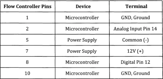
For the flow sensor output signal we connected pin 2 of the flow controller's D-connector to the microcontroller's analog input pin 14 and pin 1 to one of the microcontroller ground pins. Pin 2 of the D-connector outputs the flow sensor's 0 to 5V analog voltage signal which is to be converted to produce a reading of the flow rate and pin 1 is the common, or ground, signal.
To control the flow controller remotely an analog signal needs to be sent to pin 8 of the D-connector and then have pin 10 connected to ground. Before connecting to pin 8 a
analog signal (See figure 10). A similar filter was made using a 3.3 kilo Ohms resistor and a 0.1 microFarads capacitor. The microcontroller's digital pin 12 was then connected to the voltage input for the PWM-to-analog converter, or low-pass filter, and the output voltage was sent to pin 8 of the flow controller's D-connector. This analog signal will be between 0 to 5V and will allow for the remote input of a setpoint value for the control valve. But before remote control of the flow controller is possible the setting of the flow controller needed to be switched from local manual input to remote input. This is done by opening the back of flow controller and moving the circuit jumper for the control settings from local control to the remote control position (See Appendix 6.3).
Lastly, the power supply for the flow controller needed to be connected. For this the 12V wall adapter which came with the system was used. The positive 12V terminal wire was connected to pin 7 of the D-connector and pin 5 was connected to the power supply common terminal.
Flow Controller Pins Device Terminal
1 Microcontroller GND, Ground
2 Microcontroller Analog Input Pin 14
5 Power Supply Common (-)
7 Power Supply 12V (+)
8 Microcontroller Digital Pin 12
10 Microcontroller GND, Ground
Table 2: The Table above shows which device, and the respective terminal, the flow controller's D-connector pins are connected to. Note: Signal converter connection between flow controller pin 8 and digital pin 12.
4.3 Numeric Keypad Connections
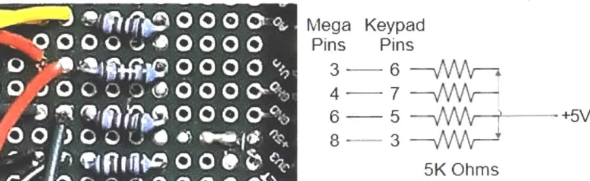
and 7 needed to be connected to the microcontrollers 5V terminal, each through a 5K Ohms resistor [11]. I then soldered four 5K ohms resistors in parallel on the prototype shield and connected them all to the same 5V source on the microcontroller board. Then I wired each resistor to one of the four pins, 3, 5, 6, and 7 on the keypad.
0 0 0 0'
Mega Keypad
0 O 0
0 0 00
Pins
Pins
0 00
0
3-6
0 006
-5
+5V0
P5K
Ohms
Figure 11: In the image on the left are the four 5K ohms resistors that were soldered onto the prototype shield. On the right is the circuit diagram for the keypad to the prototype board.
Next was to wire all of the seven pins on the keypad each to its own digital input terminal on the microcontroller board. Pins 1,2, and 4 were connected directly from the keypad to a
microcontroller terminal but the pins wired already to a resistor on the prototype board were wired in series with a microcontroller terminal[11].
Keypad Pins Microcontroller Digital Pins
1 7 2 5 3 8 4 2 5 6 6 3 7 4
Table 3: The table above shows which digital input pins the keypad pins get wired to. Note: Pins 3, 5, 6,and 7 are also connected to resistors as described in the text above.
4.4 LCD Display Connections
The last thing that needed to be connected was the lcd display and as mentioned earlier this was greatly simplified by the microcontroller board that was preinstalled on the back of it. With the
preinstalled board the connections were reduced to four, the ground, or GND, the voltage input, or
Vcc, SDA, and SCL, as shown in figure 11.
Figure 12: A close up to the microcontroller
board on the back of the lcd display and shows the four wire pins, GND,Vcc, SDA and ,SCL.
*wobt Arduino LCM602 IIC
The GND connection was connected to a ground terminal on the Mega microcontroller
board, the Vcc to a 5V terminal, the SDA to terminal 20, and SDL to terminal 21. Terminal 20 and 21
of the microcontroller boards are the serial data line (SDA) and the serial clock line (SCL) which allow for communication with devices like microcontroller on the lcd display [9].
LCD Display Pins
Microcontroller Terminals
GND GND
Vcc 5V
SDA 20
SCL 21
Table 4: The table above shows the microcontroller
terminals the lcd pins are wired to.
4.5 Code
Once all of the components were properly connected the next step was to write the code for the system. Using the open source Arduino software, code was developed to be able to input a flow
are displayed on the lcd. The code also asks for the microcontroller to read the output voltage signal from the flow rate sensor and converts that to a reading that is displayed on the lcd screen to allow for an accurate monitoring of the fluid flow (See Appendix 6.8 for code).
5.
Results, Conclusions and Future Work
I believe with this project I was able to produce a suitable control system for the
torrefaction reactor it was meant for. Using the produced system a user is able to input both the desired motor speed and flow setpoint values which are then sent to control their respective component.
Through testing the control system developed it showed that it was able to control both the motor speed and fluid flow rate using the values inputted using the numeric keypad but showed to produce errors in the control of the flow controller setpoint. The motor speed is also suspected to be affected but due to its low speeds it does not seem to be greatly impacted. A possible source for error is believed to be caused by the ripple in the voltage that comes from the PWM-to-analog converter. To reduce the ripple of the analog signal's voltage additional filters can be installed or the current components of the circuit can be changed. By changing the sizes of the components in the PWM-to-analog converter, which can be determined using the online calculator previously mentioned, the ripple in the analog signal can be reduced and should greatly increase the precision of control of both the motor speed and flow rate [8]. My suggestion for the replacement
components would be to switch the current 3.3K Ohms resistor with a 1M Ohms resistor, and the 0.1 microfarads capacitor with a 0.3 microfarads capacitor.
Another possible source of error is believed to be from the microcontroller board not outputting or reading the exact voltages. This would affect the inputted flow controller setpoint, motor speed as well as displayed flow sensor reading. A way to possibly remedy this would be to
perform tests on the input/output voltages using a voltmeter. If these tests exhibit any
discrepancies with the expected values the code should be modified to attempt to correct them. Further tests should also be performed to see if the error is a manufacturing error of the microcontroller board or of the attached prototype shield.
Moving forward I hope that further work can go into fine tuning the system but also on making it more compact and robust. The microcontroller board used in this application is widely used for prototyping purposes and does possess additional features not utilized in this application that can be removed by developing a board specific for its application. Once this is done a suitable housing component can be designed for the electronics to provide protection from the elements. A CAD model for a possible housing for the electronics was developed to show a possible design using the current system. A separate housing was developed for the motor driver but neither housing was able to be materialized due to time running out (See Appendix 6.9 for CAD models).
I extremely enjoyed working on this project and wish I had more time to personally further its development. The system developed has much room for improvement but I believe it can be extremely useful for the torrefaction reactor it was developed for once refined.
6. Appendix
6.1 Bison Motor
Wire
Motor Armature
Red Positive (+) Black Negative (-)
Green Ground Table 5: Bison motor wires [4].
Figure 13: Bison motor.
Maker Bison Engineering Corp.
Model 336 Series Speed at 90V (RPM) 8.7 Speed at 130V (RPM) 13 Torque (in-lbs) 293 Input HP 1/20 Amps 0.60
Brush Motor Yes
6.2 Flow Controller D-Connector Pin Functions
Pin Function
0 to 5 VDC Flow Signal Common 0 to 5 VDC Flow Signal Output Common
Open (Purge)
Common, Power Supply Unassigned
+12VDC (+24VDC*) Power Supply Remote Setpoint Input
4 to 20mA (-) Flow Signal Return Remote Setpoint Common
+5 VDC Reference Output for Remote Setpoint Valve Off Control
Auxiliary +12 VDC (+24 VDC)
4 to 20 mA (+) Flow Signal Output Chassis Ground
8
7
6
5....,.
4-3
2
0
0 0
00
00
00
00
00
Or
5
Figure 14: The diagram above is of the flow controller's D-connector showing the number assigned to each pin [7]. 1 2 3 4 5 6 7 8 9 10 11 12 13 14 15
/15
14
- 12
ft--11
.1
6.3 Flow Controller Jumper Locations
RA34 ZERO POTENTIOMETER 14.11 ONTROL OaKcU1PERS R1 ESPONSE TIME ADJUSTMENT SPAR 0%) R40 100% R39 75% A9 is 4 7 1 13 A 0 C D EFigure 15: A diagram of the back of the flow controller from the user manual on the left. On the right is a close up to the control circuit jumpers grid which is used for placement of the jumpers [7]. There are three basic valve control options which can be adjusted through the NJ1 control circuit jumpers.
(a)
(b) (c)
Local or Remote control.
0 to 5V or 4 to 20mA setpoint signal. 2% cutoff active or not active.
FUNCTION
NJ1-A
NJ1-B
NJ1-C
NJ1-D
NJ1-E
Oto5V
2-3 5-6 8-9 4to20mA 1-2 4-5 7-8 Local 11-12 Remote 10 -112% Cutoff On
13-14
2% Cutoff Off
14-15
Table 7: The table above shows the jumper configurations for the different settings. Default
factory settings are: Local, 0 to 5V, and 2% cutoff off [7].
--1 GFC 17 /371141 NR7 GFC ; /7177
.
L,,..3,,
R38 W%6.4 Mega 2560 Rev 3 Microcontroller
Responsible for
USB communication
USB Connector Fuse for USB protection Regulator 5V SOURCE 7 to 12V PWM Outputs Serial TWI (12C) CommunicationsPower Pins Analog Inputs Regulator 3.3V
Figure
16: A similar Mega 2560 microcontroller by Arduino.Digital Inputs/Outputs Reset button Microcontroller ATmega2560 Operating Voltage 5V Input Voltage 7-12V (recommended)
Input Voltage (limit) 6-20V
Digital I/O Pins 54
Analog Input Pins 16
DC Current per I/O Pin 20 mA
DC Current for 3.3V Pin 50 mA
Flash Memory 256 KB
6.5 Minarik Motor Driver
Li AC Power (+) L2 AC Power (-) Al Motor Arm. (+) A2 Motor Arm. (-) S1 Signal Common S2 Signal InputTable 9: Motor driver connection block ports [6].
Maker Minarik Drives
Model Number XPO2-115AC-Q
Max. Current 2
Input Voltage (VAC) 115
Output Voltage (VDC) 0 - 130
Power Range (HP) 1/20 - 1/6
Field / Shunt Supply No
Reversing No
Isolation No
6.6 Numeric Keypad Matrix
to-
t f
30
K
Oas010
a
0 0
121 45
0O
I
Oft 0200*
I1" 51
Figure 17: The diagrams above depict how the 12-buttons of the numeric keypad are connected in
a matrix format.
6.7 PWM-to-Analog Converter
PWM
signal
-+4R
C
-+Vout(s)
Figure 18: A circuit diagram of the low-pass filter that
was used to convert the microcontroller's PWM signal
to an appropriate analog voltage signal [8].
ro
n
1E2J
40
INSr151,
I
I
)
LC
0 __103
LA
t I I6.8 Code
#include <Keypad.h> #include <Wire.h>
#include <LiquidCrystal_12C.h>
LiquidCrystal_12C lcd(Ox3F,20,4); // set the LCD address to Ox3F for a 20 chars and 4 line display //initializing keypad
const byte ROWS = 4; //four rows for keypad membrane const byte COLS = 3; //four columns for keypad membrane //define the symbols on the buttons of the keypads
char hexaKeys[ROWS][COLS] =
{
{I
1 1, 121,13 l{ 14151,1611,
{'7','8''19 }
byte rowPins[ROWS] = {5, 4, 3, 2}; //connect to the row pinouts of the keypad byte colPins[COLS] = {8, 7, 6}; //connect to the column pinouts of the keypad //initialize an instance of class NewKeypad
Keypad keypad = Keypad(makeKeymap(hexaKeys), rowPins, colPins, ROWS, COLS);
int flowReadPin = 14; // Reads Pin [14], output voltage caused by the current flow sesnsor float flowReadValue = 0; //flow sensor value, 0-5V but microcontroller reads it as 0-1023 float flowReadDisplayed = 0; //converted A to a 0-50.00 L/min to output to display
const int numReadings = 20; //determine the sizes of flow readings in the index int flowReadings[numReadings]; //the readings from the analog input
int readIndex = 0; //number of readings in the index above float total = 0; /add value of all the readings in the index
float avgflowReadValue = 0; //the total divided by number of readings int setPointPin = 12; //signal to Pin [12] to control flow, 0-5V
float setPoint = 0; //input signal 0-50 L/min float setPointVolt = 0; //converted A to 0-5V
float setPointValue = 0; //converted A to 0-255 for analog signal to flowmeter
int motorspeedPin = 13; //signal to Pin [13] to control motor speed float motorspeed = 0; /input signal 0-13 RPM
float motorspeedValue = 0; //converted A to 0-255 for analog signal to motor driver
void setup(
{
Serial.begin(9600);
lcd.init(; //initialize lcd
lcd.backlight(; //turns on backlight
lcd.begin(20, 4); // set up the LCD's number of columns and rows lcd.noAutoscroll();
keypad.setDebounceTime(10);
pinMode(setPointPin, OUTPUT); //sets degital Pin [12] as an output
pinMode(motorspeedPin, OUTPUT); //sets digital Pin [13] as an output
lcd.print("Welcome!"); //prints "Welcome!"
delay(2000);
microVoltage = 4.951; //max output voltage of microcontroller
void flowrateEntry({
lcd.clear(J; //clears screen
Icd.setCursor(0, 0); //sets cursor to starting position
lcd.print("Enter flow rate:"); //prints "Enter flow rate:" on the first row lcd.setCursor(0, 1); //moves cursor to the start of row 2
lcd.print("00.0 L/min"); //prints "00.0 L/min" on the 2nd row lcd.setCursor(0, 1); //moves cursor back to (0,1)
lcd.cursor(); //sets a visible cursor to show position
}
float GetFlow() //function gets a value for setpoint of flow
{
float flowInput = 0; //creates the "flowlnput" variable int i = 0; //creates a variable that will be incremented
char key = keypad.getKey(; //creates variable "key" and sets it to whatever is inputted
break;
case '0': case '1': case '2': case '3': case '4': //case when a number is inputted case '5': case '6': case '7': case '8': case '9':
if (i == 0) //takes in the 1st value
{
flowInput = 10*(key - '0'); //stores tens value in "flowlnput"
if (flowInput > 50) //compares "flowlnput" to max flowrate which is 50 L/min
{
Icd.setCursor(0, 1); lcd.print("Invalid lcd.noCursor(; delay(1000); flowInput = 0; i = 0; lcd.cursor); lcd.setCursor(0, 1); lcd.print("00.0 L/mi lcd.setCursor(0, 1);}
else { lcd.print(key); i++;}
}
else if (i == 1){
flowInput = flowInput if (flowInput > 50)"); //if greater tha 50 prints "Invalid"
//resets "flowinput" //resets "i"
n"); //resets screen
//if "flowlnput" is less than 50 it will print the key value //increments "i", i =1
+ (key - '0'); //stores ones value in "flowlnput"
//compares "flowlnput" to max flowrate which is 50 L/min ex. 53 { lcd.setCursor(0, 1); lcd.print("Invalid lcd.noCursor(; delay(1000); flowInput = 0; i = 0; lcd.cursor(; lcd.setCursor(0, 1); lcd.print("00.0 L/min"); lcd.setCursor(0, 1); I else
{
lcd.print(key); //if "flowlnput" is less than 50 it will print the key value
} }
else if (i == 2) {
flowlnput = flowlnput + 0.1 * (key -'0'); //stores tenths value in "flowlnput"
if (flowInput > 50) //compares "flowInput" to max flowrate which is 50 L/min ex.
{
lcd.setCursor(0, 1); lcd.print("Invalid lcd.noCursor); delay(1000); flowInput = 0; i = 0; lcd.cursor(; lcd.setCursor(0, 1); lcd.print("00.0 L/min"); lcd.setCursor(0, 1);}
else { lcd.print(key); lcd.noCursor(;//if "flowInput" is less than 50 it will print the key value //removes cursor to show no more inputs are needed //increments "i", i=3. When i=3 program breaks out
}
}
break; case '*': flowInput = 0; i = 0; lcd.setCursor(0, 1); lcd.print("00.0 L/min"); lcd.setCursor(0, 1); lcd.cursor); break;//if'*' is inputted program will reset
key = keypad.getKey); //programs takes in inputted key and then goes into switch 50.3
void setPointOutput() //global function that convertes {
setPoint = GetFlow(; //calls 'GetFlow' for setpoint value
setPointValue = setPoint * (255.0/50.0); //converting the inputted setPoint of 0-50L/min to 0-255 for the analogWrite
}
void motorspeedEntry()
f
lcd.setCursor(0, 2); //moves cursor to the start of row 3
lcd.print("Enter motor speed:"); //prints "Enter motor speed:" on the 3rd row lcd.setCursor(0,3);
lcd.print("00.0 RPM");
lcd.setCursor(0,3); lcd.cursor(;
}
//moves cursor to the start of row 4 //moves cursor back to the start of row 4 //sets a visible cursor
float GetMotorSpeed() //function gets value for motor speed, look at GetFlow() for ex.
{
float motorspeedInput = 0; //creates variable 'motorspeedlnput' int
j
= 0; //creates increment variable 'j'char key = keypad.getKey);
delay(50); while(key != '#' &&j < 3) { switch (key)
{
case NOKEY: break; case '0': case case '5': case if (j == 0){
'1': case '2': case '3': case '4': '6': case '7': case '8': case '9':
motorspeedlnput = 10*(key if(motorspeedlnput > 13)
{
lcd.setCursor(0, 3); 1cd.print("Invalid lcd.noCursor(; delay(1000); motorspeedlnput = 0; j = 0; -'0');//max motor speed is 13 RPM
lcd.setCursor(O, 3); lcd.print("00.0 RPM"); lcd.setCursor(O, 3);
}
else{
lcd.print(key);j++;
}
}
else if (j == 1){
motorspeedinput = motorspeedInput +(key - '0'); if(motorspeedlnput > 13)
{
lcd.setCursor(0, 3); lcd.print("Invalid lcd.noCursor); delay(1000); motorspeedlnput = 0; j = 0; lcd.cursor(; lcd.setCursor(0, 3); lcd.print("00.0 RPM"); lcd.setCursor(0, 3); } else{
lcd.print(key); lcd.setCursor(3, 3);j++;
}
}
else if (j == 2){
motorspeedInput = motorspeedInput + 0.1*(key -'0'); if(motorspeedlnput > 13)
{
lcd.setCursor(0, 3); lcd.print("Invalid lcd.noCursor(;
lcd.setCursor(0, 3); } else { lcd.print(key);
j++;
lcd.noCursor();}
break; case '*': motorspeedlnput = 0; j = 0; lcd.setCursor(0,3); lcd.print("00.0 RPM"); lcd.setCursor(0,3); lcd.cursor(; break; I key = keypad.getKey); I return motorspeedInput; I void motorspeedOutput (){
motorspeed = GetMotorSpeed(; //gets 'GetMotorSpeed' for motorspeed value, between 0-13 motorspeedValue = 255.0 * (motorspeed/13.0); //convert 0-13 inputted motor speed to 0-255 for analogWrite i void readFlow()
{
flowReadValue = analogRead(flowReadPin); 0-1023total = total -flowReadings[readlndex]; flowReadings[readlndex] = flowReadValue; average
total = total + flowReadings[readIndex]; readlndex = readIndex +1;
if (readIndex >= numReadings)
// reads the input pin and gets a value between
readIndex =0;
}
avgflowReadValue = total / numReadings;
flowReadDisplayed = avgflowReadValue * 50.0/1023.0; //converting the value of 0-1023 to 0-50
L/min
Icd.setCursor(0, 1); lcd.print("FlowRate:");
lcd.print(flowReadDisplayed, 2); //prints current flowrate, to 2 decimal places lcd.print("L/min"); delay (100);
}
void Running()
{
lcd.noCursor); lcd.clear(; lcd.setCursor(0, 0); lcd.print("Setpoint:");lcd.print(setPoint, 1); //prints inputted setpoint value lcd.print("L/min");
lcd.setCursor(0, 2); lcd.print("Motor Speed:");
lcd.print(motorspeed, 1); //prints inputted motorspeed value lcd.print(" RPM");
char key = keypad.getKey); delay(50);
while (key !='#') //while '#' is not press motor and flow controller will operate
{
analogWrite(motorspeedPin, motorspeedValue); //sending a pwm from motorspeedPin that will be converted to an analog signal that will control the motor
analogWrite(setPointPin, setPointValue); //sending a pwm from setPointPin that will be converted to an analog signal that will set the flow
readFlow(;
switch(key) //nothing will happen if other keys are pressed
{
}
}
void Reset() //resets motorspeed and setpoint to 0 to restart program
{
motorspeedValue = 0; setPointValue = 0; analogWrite(motorspeedPin, motorspeedValue); analogWrite(setPointPin, setPointValue); } void loop()I
flowrateEntry(; //screen requests user to enter desired flowrate
setPointOutput(; //takes in the input flow and puts out the setpoint signal motorspeedEntry);// screen requests user to enter desired motor speed
motorspeedOutput); //takes in the input motor speed and puts out the motor speed signal Running(; //runs the components
Reset(; //resets program }
6.8 Housing
Figure 19: CAD models of a housing for the motor driver and a on/off switch.
7.
References
[1] Arduino's Analog Write - Converting PWM to a Voltage. (n.d.). Retrieved November 8, 2017,
from https://provideyourown.com/2011/analogwrite-convert-pwm-to -voltage/
[2] Arduino Mega. (n.d.). Retrieved November 05, 2017, from
https://www.arduino.cc/en/Main/ArduinoBoardMega
[3] Basu, Prabir. ( D 2013). Biomass gasification, pyrolysis and torrefaction: practical design and
theory, second edition. [Books24x7 version] Available from
http://common.books24x7.com.libproxy.mit.edu/toc.aspx?bookid=56515.
[4] Bison - Gear & Engineering Corp. (n.d.). Retrieved October 15, 2017, from
https://www.bisongear.com/011-336-1208.html
[5] Brain, M. (2000, April 01). How Microcontrollers Work. Retrieved January 05, 2018, from https://electronics.howstuffworks.com/microcontrollerl.htm
[6] Minarik Drives. (n.d.). XP02-11SAC-Q: User's Manual. Retrieved from https://www.minarikdrives.com/xp02-115ac-q
[7] Omega. (2001). FMA 5400/FMA 5500 Mass Flow Controllers: User's Guide. Retrieved from https://www.omega.com/manuals/manualpdf/M2898.pdf
[8] RC Low-pass Filter Design. (n.d.). Retrieved November 15, 2017, from
http://sim.okawa-denshi.jp/en/PWMtool.php
[9] Smraza 2004 LCD Display Module. (2017, August 16). Retrieved December 5, 2017, from
http://www.miniarduino.com/smraza-2004-lcd-display-module-20-characters-x-4-lines-fo r-arduino-uno-r3-mega2560-nano-adp01/
[10] Speed Controllers. (2005, October 5). Retrieved December 14, 2017, from
http://homepages.which.net/-paul.hills/SpeedControl/SpeedControllersBody.html
[11] Using the Sparkfun 12 Button Keypad, With the Arduino. (n.d.). Retrieved November 10, 2017,
from
[12] What is a Mass Flow Controller? (n.d.). Retrieved January 06, 2018, from
http://www.horiba.com/horiba-stec/products/mass-flow-technology/what-is-a-mass-flo w-controller/