Design of a Fail-Safe Wearable Robot with Novel
Extendable Arms for Ergonomic Accommodation
during Floor Work
by
Katie S. Hahm
B.S. Stanford University (2017)
Submitted to the Department of Mechanical Engineering
in partial fulfillment of the requirements for the degree of
Master of Science in Mechanical Engineering
at the
MASSACHUSETTS INSTITUTE OF TECHNOLOGY
June 2019
@
Massachusetts Institute of Technology 2019. All rights reserved.
Signature redacted
Author ...
Department of Mechanical Engineering
May 9, 2019
Certified by...
. . . ..Signature
-redacted
H. Harry Asada
,
eLr&Professor of Engineering
1nature redacteds.
Supervisor
Accepted by..
M S ITUTE OF TECHNOLOGYJUN
JN13
20j
LIBRARIES
...I
.... . . . .Nicolas Hadjiconstantinou
Chairman, Department Committee on Graduate Theses
Design of a Fail-Safe Wearable Robot with Novel Extendable
Arms for Ergonomic Accommodation during Floor Work
by
Katie S. Hahm
Submitted to the Department of Mechanical Engineering on May 9, 2019, in partial fulfillment of the
requirements for the degree of
Master of Science in Mechanical Engineering
Abstract
Aircraft manufacturing, construction, and agricultural production often involve work-ers maintaining uncomfortable postures, such as stooping and kneeling, for extended periods of time. We present a wearable robot, named MantisBot Alpha, that con-sists of two expandable robotic arms that brace a worker near the ground. It allows them to perform bi-manual tasks and assists them in standing up and kneeling down. The key component of this new design is a novel linkage mechanism that provides adjustment of both the worker's distance to the ground and the tilt of their torso. The mechanism link parameters are optimized such that a) its expansion rate is high enough, 1:2.43, to push off the human body from the ground and fully contract the scissor arm when not used, and b) it allows the worker to reach within a larger work-ing space while c) it is light enough for wearability. The linkage mechanism avoids the singularity problem in standard scissor mechanisms. The mechanical design of the system ensures it is fail-safe. A prototype has been fabricated to demonstrate the feasibility of the system.
Keywords: Human Augmentation, Supernumerary Robotic Limbs, Exoskeletons, Mechanism Design, Industrial Robotics
Thesis Supervisor: H. Harry Asada Title: Ford Professor of Engineering
Acknowledgments
I would like to thank the folks that poured me love and raised me to be who I am
today: my mom Ah-hyung Lim (I] }), my dad Yeong-ook Hahm (79 4--), my
grandmas, and my extended family. I attribute every bit of my success to your love.
I would like to thank my circles of friends for the laughter we shared and for
pushing me along when life didn't go as planned. Thank you for the warmth, the adventures, and the shenanigans.
I would like to thank the countless teachers I have been lucky enough to meet, both formal and informal, for showing me what is and what could be. I would like to specifically thank Mrs. Anne Thatcher, Dr. David Christensen, and the community at APIENC.
Lastly, I would like to thank Professor Asada and the d'Arbeloff lab members for their boundless inspiration, mentorship, and insight. These last two years have been a blast.
Contents
1 Introduction 13
1.1 M otivation . . . . 13
1.2 Existing Solutions . . . . 14
1.2.1 Passive Assistive Devices . . . . 14
1.2.2 Exoskeletons . . . . 15
1.2.3 Previous MantisBot . . . . 16
2 Functional and Design Requirements 19 2.1 Task Specifications . . . . 19
2.2 Functional Requirements . . . . 19
2.3 Design Requirements . . . . 21
3 Design Exploration 27 3.1 Scissor Mechanism . . . . 27
3.2 Novel Scissor Mechanism . . . . 29
4 Kinematic Analysis 31 4.1 2D Kinematics and the Workspace . . . . 31
4.2 3D Coordinated Motion Control . . . . 36
4.3 Actuator Output Analysis . . . . 37
4.4 Structural Analysis . . . . 39
5 Design Implementation and Evaluation 45 5.1 Detailed Module Design . . . . 45
5.2 Prototype . . . . 48 5.3 Testing . . . . 49
List of Figures
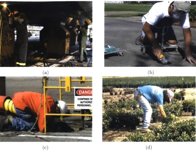
1-1 Various awkward postures sustained by workers and an attempt to
relieve the stress with a passive device. a) Shipbuilding welders twist
their torso to reach the low ceiling
[2]
b) A passive dolly redistributesthe worker's weight from his knees to his torso [3]. c) A construction worker kneels to reach below the ground [6]. d) An agriculture worker
stoops their back [18]. . . . . 14
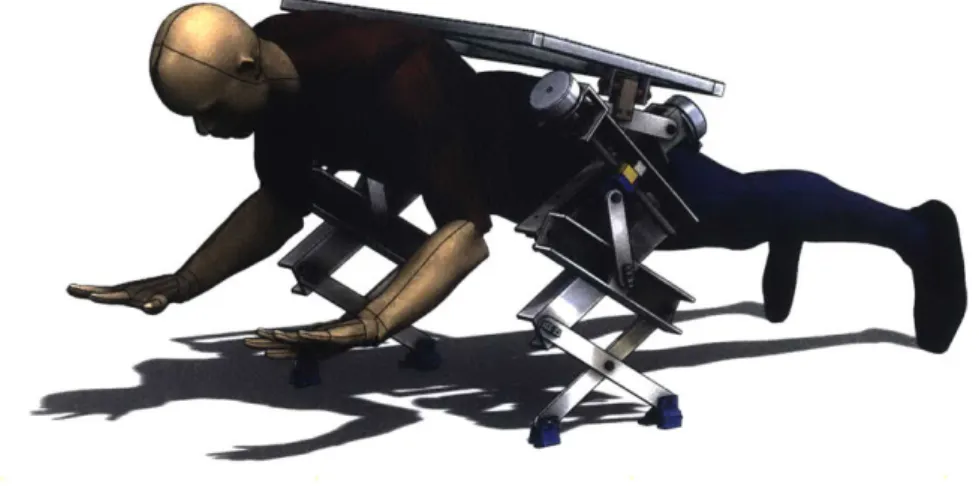
1-2 The Mantisbot Alpha concept with Supernumerary Robotic Limbs (SRLs). The SRLs support the upper half of the body and allow the
worker to perform bi-manual tasks. . . . . 15
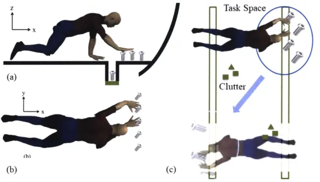
2-1 The aircraft final assembly work environment. In (a) the worker uses
one arm to support himself while using the other arm to screw bolts. The bolts can be on the floor or under the floor. In (b) the worker must move in the y direction to complete the task. In (c) the task spaces are at different locations with clutter between. Therefore, wheels cannot
b e used . . . . 20
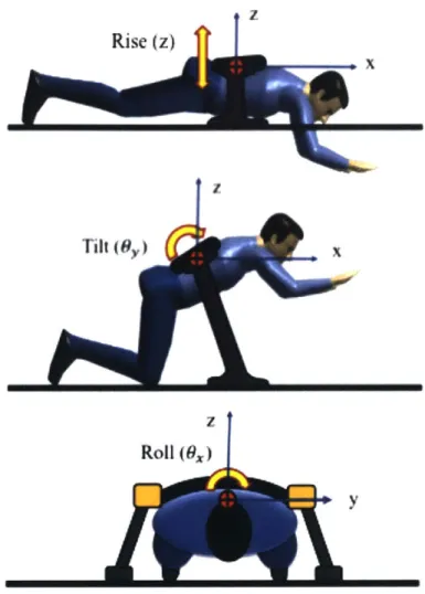
2-2 The robot coordinate frame and the three degrees of freedom illustrated on the MantisBot Alpha. We define the coordinate system such that
x points towards the head, and y-z spans the transverse plane. ... 24
2-3 The 6 active, passive, and locked degrees of freedom. The robot is
therefore a self-standing, stable system. . . . . 25
3-2 The traditional scissor mechanism juxtaposed to a novel scissor mech-anism. The blue lines are the input actuators, and the red lines are the lever arms. Given linearly spaced inputs, we can observe the sparseness of the blue endpoints and infer where the system approaches singular-ity. The traditional scissor endpoints are more sparse when the scissor is contracted, whereas the novel scissor endpoints are more sparse when the scissor is expanded. This supports that the traditional mechanism approaches singularity toward contraction, and that the new
mecha-nism approaches singularity toward expansion. . . . . 28
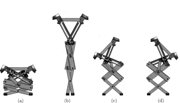
3-3 A CAD model of the linkage mechanism demonstrating both its large
expansion ratio and its ability to tilt. . . . . 30
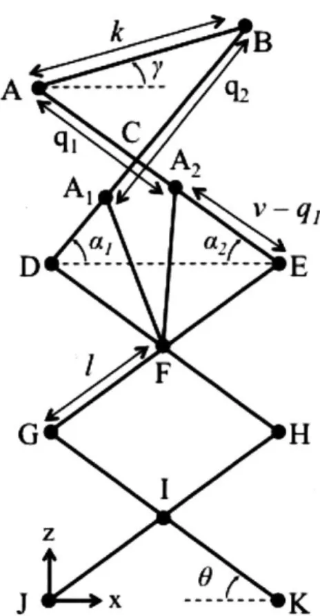
4-1 The reference 2D diagram representing the linkage configuration of the
robot. We define Point J as the origin in the x - z plane as shown.
Point C is not a pin joint, but merely where linkages AE and BD
crosses over. . . . . 32
4-2 (a) the input pair values, (c) their corresponding output in the 2D
workspace, and (e) their corresponding gamma values. The regular workspace includes orientations that are not practical, such as the head of the user hitting the ground. These points have been omitted to show the desired input pairs and their corresponding workspace. (b) shows the desired input pair values, (d) shows the desired workspace, and (f)
shows the desired gamma values. . . . . 35
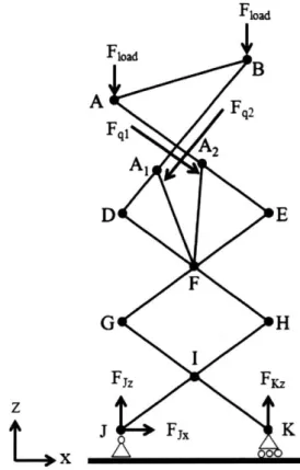
4-3 A free body diagram of the 2D scissor mechanism. Joint J is modeled as a pin joint, and joint K is modeled as a roller joint. External forces
occur at A and B due to the user's weight, applied forces occur at A1
and A2 due to the actuator outputs, and reaction forces occur at J and
K. ... ... 37
4-4 The required actuator outputs at different expanion heights. The plot
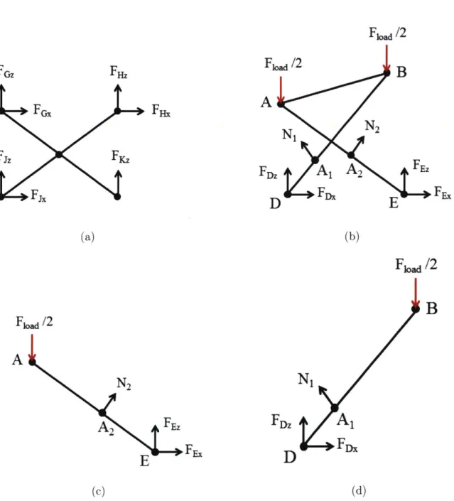
4-5 The free body diagrams used for static loading analysis. (a) The over-all FBD showing external forces. (b) The FBD of the lowest scissor linkages (c) The FBD of the upper scissor linkages (d) The FBD of
linkage AE (e) The FBD of linkage BD. . . . . 40
4-6 The maximum tensile forces and bending moments in different configu-rations. The forces and moments in other beams are not illustrated as they are smaller and thus not relevant when determining beam
cross-section geometry from maximum loadings. . . . . 43
5-1 (a)A CAD cross-section model of the linear guide design. The
lead-screw takes axial load while the linear guide takes the radial load. The flexure at the base of the leadscrew relieves the module from being over-constrained. A flexible coupling relieves the motor from axial and radial misalignment. (b) A CAD cross-section model of the pin joint with bushings. The press-fitted bronze bushings and bearings allow link 1 to rotate about link 2 and the shoulder bolt. The shoulder bolt
is screwed into link 2 using a backpiece that is fixed onto the link. 46
5-2 The author wearing the MantisBot Alpha prototype. . . . . 48
5-3 (a) The actual motor current and (b) the resulting torque output.
Neg-ative position counter indicates the robot arm is moving up, towards expansion. We can observe that the torque output increases as it ap-proaches expansion, which is consistent with the previous singularity
Chapter 1
Introduction
1.1
Motivation
Aircraft assembly, flooring and tile placement, berry picking, and many other con-struction, agriculture, and manufacturing jobs require that workers hold uncomfort-able postures, such as crouching, stooping, or kneeling, for long periods of time. See Fig. 1-1. Consequently, many workers sustain long-term work-related musculoskeletal disorders (MSD) [9]. In the United States, MSD accounted for 32.2% of total
nonfa-tal occupational injuries and illnesses for workers in all industries
[7].
MSD adverselyaffects quality of life. 41% of patients report that MSD has a negative effect on their social relationships, 47.8% report that MSD disturbs their sleep, and 30% report that they encounter much difficulty when rising from the floor amongst other daily tasks
[8]. This persistent health issue also results in both loss of productivity and a steep
economic price. In the United States, MSD incidents resulted in over 4 million lost days from work [7]. Nonfatal injuries in 2007 had cost estimates of 186 billion dollars
[14].
Biomechanical analysis has been performed to examine these ergonomically chal-lenging postures. With supervised motion tensor decomposition, postures such as kneeling, stooping, and reaching are identified as awkward postures [9] 111]. An al-ternative to stooping or kneeling are prone postures, which assumes a more neutral spinal posture while allowing the worker to reach the ground, and provides
signifi-(a) (1)
PKABOPUEL
(c) (d)
Figure 1-1: Various awkward postures sustained by workers and an attempt to relieve the stress with a passive device. a) Shipbuilding welders twist their torso to reach the low ceiling [2] b) A passive dolly redistributes the worker's weight from his knees to his torso [3]. c) A construction worker kneels to reach below the ground [6]. d) An agriculture worker stoops their back [18].
cantly less discomfort [17]. In this paper we aim to provide a worker with a more ergonomic workspace by giving them extra extendable arms that support them in this prone position (see Fig. 1-2).
1.2
Existing Solutions
1.2.1
Passive Assistive Devices
Passive products have been used by construction workers to adjust their posture to fit their environments. In Fig. 1-1b, a worker leans against a dolly that supports both their knees and torso, distributing the load otherwise borne by the knees. Padded
Figure 1-2: The Mantisbot Alpha concept with Supernumerary Robotic Limbs (SRLs). The SRLs support the upper half of the body and allow the worker to perform bi-manual tasks.
creepers are commonly used to access low-ceiling areas or to access below ground environments. Workers can lean on simple body support bags to reach difficult areas along a deep, curved wall. These products successfully free up both the worker's hands, allowing them to perform bi-manual tasks.
While passive products are trustworthy due to their transparent functionality, none of these devices can be used universally in different environments. In addition, these devices lock the user into one posture, leaving only their feet or knees to push and pull to allow for minor adjustments. Lastly, they become bulky and inconvenient when the worker must readjust their posture or move to a different location.
1.2.2
Exoskeletons
To allow for more flexibility and seamless integration with the user, human aug-mentation robotic systems can be considered. Exoskeleton robots used by Daewoo Shipbuilding can assist in bearing heavy loads, reducing the loads borne by the work-ers [15]. The user wears robotic limbs along their natural limbs, and the actuator increases the torque at the user's natural joints, relieving the force borne by the user's muscles. Although they are conveniently wearable, exoskeletons move in parallel with the user's natural limbs. Crouching, stooping, and kneeling postures are unnatural
and ergonomically challenging because the human body structure is not suitable for taking these postures for extended periods of time. An exoskeleton amplifies an oper-ator's joint torques, but it does not solve the root problem: the inadequate skeletal, kinematic structure of the human body.
Supernumerary Robotic Limbs (SRLs) provide an alternative to exoskeletons by supplementing and augmenting the human kinematic structure instead of enhancing an existing functionality. The robotic limbs do not move in parallel with the user's limbs, but rather acts as a third or fourth limb thus providing new functionality [16].
1.2.3
Previous MantisBot
A previous prototype, the MantisBot [13], had been developed to provide support for
near-ground work. With this prototype, we performed preliminary testing at an air-craft final assembly site, where the testers provided valuable feedback and highlighted several drawbacks.
From the testing, we observed that:
" The MantisBot was too heavy; it required even more muscular effort when
standing up and kneeling down while wearing the heavy apparatus.
" The testers could not fully trust the machine - they placed their palms on the ground for support and the robotic feet were prone to slip.
" Instead of placing their knees on the floor as intended, they used their feet and
maintained a push-up position.
" The robot was prone to catastrophic failure in case of power loss.
In addition, the testers gave verbal feedback on their review of the previous Man-tisBot:
" Keeping their hands free was convenient
" There needed to be hard mechanical stops or sensory feedback alarms that warn
the wearer from moving beyond the supported range of the system
" There cannot be surprises to the wearer
" Usage should be intuitive and require minimal training and adjustment
Taking these results into consideration and understanding the shortcomings of other solutions, the MantisBot Alpha was developed to assist workers in performing near-ground tasks.
In this paper, we present the design of the MantisBot Alpha, shown in Fig. 1-2, as follows: In Chapter 1-2, we explore the functional and design requirements of a human augmentation system for near floor work, and discuss the mechanisms and its modifications as it applies to the requirements; in Chapter 3 we explore possible
design solutions that meet the requirements; in Chapter 4 we perform kinematic and
structural analysis of the design concept to optimize for workspace range; In Chapter
5 we explain the implementation details including the machine design, the prototype,
and it's testing; and in Chapter 6 we discuss any future work involving the MantisBot Alpha.
Chapter 2
Functional and Design Requirements
In this section, we define the task, the functional requirements of the robot, and the design requirements derived from the functional requirements.
2.1
Task Specifications
The specific task we consider in the current work is aircraft final assembly, which largely relies on manual labor. Fig. 2-1 shows the work environment in this setting. The task must be performed both at and below the floor level. As shown in Fig. 2-la, the worker has to reach the floor and below the floor. As shown in Fig. 2-1b, the worker must also move side-to-side. Fig. 2-1c is a common task space where workers have to perform a series of manufacturing operations, where they must relocate often and take a crouching or crawling posture. Particularly for older workers, it is fatiguing to make repetitive transitions between standing and crouching. The floor environment is usually cluttered with various obstacles and difficult to use wheels to transfer loads.
2.2
Functional Requirements
The design of the SRLs was driven by the feedback from preliminary testing and is
determined by the following specific functional requirements:
(a) Task Space C9tter P (h) (b) (c)
U
Figure 2-1: The aircraft final assembly work environment. In (a) the worker uses one arm to support himself while using the other arm to screw bolts. The bolts can be on the floor or under the floor. In (b) the worker must move in the y direction to complete the task. In (c) the task spaces are at different locations with clutter between. Therefore, wheels cannot be used.
We will specifically address environments shown in Fig. 2-1c.
" Must support a user weighing up to 300lbs.
* Must be safe in case of electronic failure.
" Must allow the user to perform a bi-manual task without significant visual or physical interference.
" Must be wearable when inactive.
" Must be adjustable to fit different body types. " Must interact with user in an intuitive way.
2.3
Design Requirements
From the functional requirements, we derive the design requirements. To first be compatible with both below the floor and on the floor work, the robot arms must be able to expand in length. For floor work, the elbow is typically locked to reduce muscle energy, while below ground work requires the elbow to bend to support the body. To augment the capabilities of the human arm, we determine the maximum height of the mechanism to be approximately the average male arm length, 78.3 cm with an extra 15 cm [1]. We determine the minimum height of the mechanism to be
approximately the average male forearm length, 41.7 cm
[1].
Therefore, we define thedesired expansion ratio as 3, or 1: 2.43.
The extra 15 cm aids in transitions between a prone working posture and a stand-ing posture. Gettstand-ing up from the ground multiple times requires much labor, espe-cially with added weights from toolbelts and a wearable robot. We can utilize the high expansion capability of the robot to lift the torso very high from the ground, allowing the feet to walk up towards the hip where the person can then stand comfortably.
Similarly, the robot can lower the person to the ground.
Next, to adjust to different fields of view and reach when working on the floor, the torso must be able to tilt and roll. We define the desired degrees of freedom as rise
(z), tilt (0,), and roll (6) demonstrated in Fig. 2-2. To actuate about these degrees of freedom, we refer back to the preliminary tests where the testers used their feet instead of knees for support. Using feet for support may provide more flexibility; the ankle is capable of hinging in two directions, dorsiflexion and and eversion, while the hip can only hinge in one direction [5][4]. Given that the foot can easily be protected from the floor with shoes, the knee is comparatively an uncomfortable option to maintain a crawling position for extended periods of time. Repeated knee stress from contact between the kneecap and the floor results in significant knee pain [12]. Thus, we adjust the indicated use posture as using the feet for support.
We also design for passive compliance in the y-direction, as the worker may mo-mentarily want to extend their reach side-to-side as shown in Fig. 2-1b. Thus we define the active degrees of freedom as z, pitch, and roll, and the passive degree of freedom in y. Fig. 2-2 illustrates the coordinate frame and active degrees of freedom relative to the user. The robot is stable in all 6 degrees of freedom. The active, passive, and locked degrees of freedom is demonstrated in Fig. 2-3.
From the preliminary testing, the testers were not willing to trust the robot. We hypothesize that one reason they could not trust the previous MantisBot was because there was no proprioceptive feedback from the robotic arms. Although the four points of contact (two robotic arms and two knees) makes the system an inherently stable system, the control of the knees is commanded by the user, while the robotic arms are controlled by the robotic system; the disconnect in communication between the two makes the system seemingly unstable and difficult to trust from the user's perspective. Therefore, we determine that the MantisBot Alpha system must have at least three points of contact with the ground to be a stable, self-standing system .
In case of a power failure, the arms must immediately lock in position, safely giving the user time to stand upright from their previous posture where their weight was distributed on the robot. We determine that our mechanism must therefore be non-backdriveable, such that the force from human weight does not collapse the mechanism if the motors lose power.
the robotic support must not lie in the user's workspace. The robot arms must be attached behind the shoulder joint and must be wide enough apart such that the user's elbows do not interfere with the robot arms.
z Rise (z) | x Iz Roll (9x) y
Figure 2-2: The robot coordinate frame and the three degrees of freedom illustrated on the MantisBot Alpha. We define the coordinate system such that x points towards the head, and y-z spans the transverse plane.
(a) Locked in x-direction.
(c) Passively actuated in y-direction.
(e) Locked in rotation about z-axis (yaw)
Figure 2-3:
(b) Actively actuated in z-direction.
(d) Actively actuated in rotation about y-axis
(pitch)
(f) Actively actuated in rotation about x-axis
(roll)
The 6 active, passive, and locked degrees of freedom. The robot is therefore a self-standing, stable system.
Chapter 3
Design Exploration
To satisfy the defined design requirements, we explore the mechanism designs that can satisfy these requirements. First, we consider the traditional scissor mechanism for its high expansion ratio. Then, we discuss a novel scissor mechanism and how its singularity configuration satisfies the desired requirements.
3.1
Scissor Mechanism
In order to meet our design concept, we consider a scissor mechanism due to its high expansion ratio capability. An example of the mechanism implemented in construc-tion is shown in Fig. 3-1. However, a typical scissor mechanism has two issues: a) it approaches a singular configuration when compressed, and b) it only provides expansion and does not allow for tilt.
Let the scissor mechanism input be a linear actuator acting at one base foot, and let the output be the endpoint of a top linkage. As illustrated in Fig. 3-2, the tradi-tional scissor mechanism output achieves high extension for a short length of input range, making it ideal for quick and large expansion. However, as it approaches lower configurations, the force required to lift the mechanism becomes larger. The linkages act as a lever arm to lift the load. In Fig. 3-2, the red lever arm vector lies along the direction of the blue input force at complete collapsed configuration, requiring infinite force to lift. Thus, the singularity lies when the scissors are completely collapsed.
Figure 3-1: A typical scissor lift used in construction [10] Traditional Ir 0.8 0.6- 0.4-0.2 A.2 Scissor Mechanism Sparse due to singularity No - leverage
0
0.2 x [m]Novel Scissor Mechanism IF 0.8-0.6. 0.4-0.2 0.4 * * S S Dense due to non-singularity Leverage
0
02 0.4 x [m]Figure 3-2: The traditional scissor mechanism juxtaposed to a novel scissor mecha-nism. The blue lines are the input actuators, and the red lines are the lever arms. Given linearly spaced inputs, we can observe the sparseness of the blue endpoints and infer where the system approaches singularity. The traditional scissor endpoints are more sparse when the scissor is contracted, whereas the novel scissor endpoints are more sparse when the scissor is expanded. This supports that the traditional mechanism approaches singularity toward contraction, and that the new mechanism approaches singularity toward expansion.
For our application, the user puts the most load on the robot when they are closest to the ground. When the torso is farther from the ground, the feet are placed closer to the torso, so the feet are able to bear higher portion of the load. In contrast, when the torso is close to the ground, the feet are farther from the torso, so the robot bears more load. Consequently, our mechanism must bear more load in compression and has less load bearing capability in expansion. This is opposite of the traditional scissor mechanism.
3.2
Novel Scissor Mechanism
We present a novel 2-DOF scissor mechanism that solves both issues of tilt and singu-larity by inverting where the singusingu-larity lies. The new mechanism and its workspace is illustrated in Fig. 3-2. Now the red lever arms and the blue linear actuators lie at a more acute angle near compression. The resulting mechanism has high force capability at compression and conversely approaches singularity towards expansion. In 3-2, the inputs are linearly spaced. Thus, the sparseness of the blue endpoints indicate where the structure approaches singularity.
The two actuators provide extension and contraction when moving simultaneously and identically. However, when they move in opposite directions, the system is not symmetric and thus tilts the top linkage. These two degrees of freedom are demon-strated in Fig. 3-3. We define the output point as the height of the right pin joint of the top linkage, making this mechanism a two input, two output system. The analysis of this system is discussed in the next section.
(b)
(a) (c) (d)
Figure 3-3: A CAD model of the linkage mechanism demonstrating both its large expansion ratio and its ability to tilt.
Chapter 4
Kinematic Analysis
To analyze the linkage mechanism, we find the forward and inverse kinematics and the Jacobian, and perform virtual work analysis and structural analysis. With these results, we can determine the robot workspace and linkage geometries. The following analysis uses variables that reference the diagram in Fig. 4-1. We define length AB
as k, length A1F and length A2F as a, length AE and BD as v, and the length JI
and its symmetric counterparts as 1. We define the two inputs as qi and q2 as the
distances AA2 and BA1 respectively. We define angles 0 = ZKJI, a1 = ZEDA1,
a2 = ZDEA2, and y = angle between the horizontal and AB.
4.1
2D Kinematics and the Workspace
To locate the system, we calculate the desired output variables as a function of the input variables. We adopt the convention that the coordinates of joint B be (B, Bz).
Given the input lengths q, and q2, we calculate the output coordinates B and -Y. It
is important to note that AB will always be length k. We use the law of cosine and
the law of sine to solve for oz1 and a2.
Using AA 1DF and AA 2EF:
a2 = (v - q2) 2
k
B
A --- Y 2q
1C
Al
v-q,
al a2D --- ---
---
E
SF
G
H
zFigure 4-1: The reference 2D diagram representing the linkage configuration of the
robot. We define Point J as the origin in the x - z plane as shown. Point C is not a
pin joint, but merely where linkages AE and BD crosses over.
a2 = (v - q1)2+ 12 - 21(v - q)
cos(a2+ 0) (4.2)
We subtract Eq. 4.2 from Eq. 4.1 to find a, - a2 as a function of qi and q2:
al - a 2 =arccos (a 2 - (v - q2)2 _ 12)/(-21(v - q2))- (4.3) arecos (a2 - (v - qi)2 _ 12)/(-21(v - qi))
Next, we find aI
+
a2 by using three equations with three unknowns: al + a2,CA1, and CA2:
Using A ABC: (4.4)
q, - CA2)2 + (q2 - CA1)2 + 2(q1 - CA2)(q2 - CA1) cos (a1 + a2)
(4.5)
Using A CA1A2:
CA1 sin ((a1 + a2 + ZCDF + ZDFA1 - ZCEF - ZEFA2)/2) =
CA2sin ((a1 + a2- ZCDF - ZDFA1 + ZCEF + ZEFA2)/2)
UsingA1A2 : (4.6)
CA1 cos ((a1 + a2 + ZCDF + ZDFA1 - ZCEF - ZEFA2)/2)
2acos ((-a1 - a2 + ZCDF + ZDFA1 + ZCEF + Z EFA2)/2)
After solving for a, + a2, we use Eq. 4.3 to find ai(qi, q2) and a2(q1, q2). We use
this result, Eq. 4.1, and Eq. 4.2 to find 0.
obtain the forward kinematics:
B = 41 sin 0 + v sin a1 (4.7)
= arcsin (sin ai - sin a2)
k
To find the inverse kinematics, we calculate qi and q2 given B2 and 'y. We use the
same equations as above.
The system of equations are too nonlinear to analytically solve for the forward and inverse kinematics and obtain a closed-form solution. Instead, we calculate the workspace iteratively. First, we find the linkage lengths from the desired minimum and maximum height defined in the design requirements. We determine that k = 0.254 m, a = 0.2032 m, v = 0.3302 m, and 1 = 0.1651 m.
Given these calculations, the final system takes the range of input qi = q2 =
[0.067m, 0.295m]. We obtain the input pairs and the corresponding workspace in Fig. 4-2a and Fig. 4-2c respectively. We state that certain extremes in the workspace will not be used as they are configurations that are either very uncomfortable or improbable for the user. For example, the torso can be at an extremely sharp angle close to the ground, as shown in Fig. 4-2e. Adjusting the inputs and obtaining the desired outputs, the desired inputs and workspace can be seen in Fig. 4-2b and Fig. 4-2d respectively, and the tilt angles can be shown in Fig. 4-2f.
Desired Input Pair Values 0.2 F 0.15F 0. 1 [ 4,+ + * ** - - ++ 0.1 0.15 0.2 0.25 0.3 q1 In] (a) 0.05'-0.05 0.1 0.15 0.2 q [m] (b)
Workspace of Point B, Origin is at Point J
-0.2
Desired Workspace of Point B, Origin is at Point J
Ir 0.8 A0.6 N 0.4[ A 0 0.2 0.4 x [m] (c)
Point B and Gamma Plotted in the Workspace
1r 0.8- 0.6-0.4
.41
-0.2 0 0.2 0.4 x [m] (e) *~1 -0.2 0 0.2 0.4 x [m] (d)Point B and Gamma Plotted in the Desired Workspace
1 r 0.8-0.6 0.4 a -0.2 0 0.2 0.4 x [im] (f) Figure 4-2: workspace,
(a) the input pair values, and (e) their corresponding
(c) their corresponding output in the 2D gamma values. The regular workspace in-cludes orientations that are not practical, such as the head of the user hitting the ground. These points have been omitted to show the desired input pairs and their
corresponding workspace. (b) shows the desired input pair values, (d) shows the
desired workspace, and (f) shows the desired gamma values.
0.3i 0.25 0.2[ 0.15F 0.1 0.05' 0.05 0.25 0.3 0.81-r0.6 N 0.4[ A2' '
4
Input Pair Values
0.3-
0.25-
4.2
3D Coordinated Motion Control
We now consider the 3D system created by the combination of two novel scissor mechanisms. To calculate the rise, pitch, and roll variables of the entire 3D system, we use the system coordinates shown in Fig. 2-2. Let the user's right robot arm have endpoints AR and BR, and the left robot arm have endpoints AL and BL- Using 2D
forward kinematics described in the previous section, we know the x and z coordinates
of these four points. Let the two arms be placed W width apart. Let the endpoint
P be the point between BR and BL, near the user's head. We define the generalized
coordinate outputs: height P, pitch OY, and roll Ox. We note that both P, and Py
directions can be actuated; however, they are residual effects and are small angles. Yaw 62 is constrained due to the geometry of the robot platform. We find the outputs:
AR+ BA+AL+-BL(48 height = P2 ~ (48) 4 pitch r O1, K=L = YR (4.9) roll = Ox ~ arctan BLz - BRz (4.10) W
-By combining the equations from Section 4.1, substituting into eq. 4.8-4.10, and
differentiating with respect to the inputs, we can obtain the Jacobian matrix of the complete system such that:
pi
qLIP2
OY =T q2 (4.11)
Fuw Fla B A Fq2 Fqi A2 A, D E F G H Fjz Fcz Fj, K
Figure 4-3: A free body diagram of the 2D scissor mechanism. Joint J is modeled as a pin joint, and joint K is modeled as a roller joint. External forces occur at A and
B due to the user's weight, applied forces occur at A1 and A2 due to the actuator
outputs, and reaction forces occur at J and K.
4.3
Actuator Output Analysis
Next, we determine the required actuator force to lift the maximum payload. We use the 2D analysis and assume each arm will take half of the user's load. With a safety factor, we assume the maximum weight borne by a single mechanism is 68 kg. Let
vertical external forces Fload act at point A and B respectively, and the total mass,
M, is shared equally such that Fload = -= 34 kg. Let actuator output forces acting
on A1 and A2 be defined as Fqi and Fq2 respectively. A free body diagram is shown
in Fig. 4-3.
From the forward kinematics, we can find A, = f(qi, q2) and B, = f(qi, q2). We
use the Principle of Virtual Work to calculate the linear actuator output force:
where F are the applied forces and r are the virtual displacements. We have: 6Work = Fq16q1 + F26q2 - Mg2 (6Bz + 6Az) = 0 6AZ = Z6q1 B q1 6BZ = a S q1 aq1 (4.14)
+
O6q2 " 9q2 tq 2Substituting Eq. 4.14 into eq. 4.13, we find:
Fqi = OB 2 Oq1 Mg {&BZ 2 tq2 (4.15)
+
Oq
o91, + Az aq2We perform these calculations iteratively. Thus, we obtain the maximum actuator force required to lift a 68 kg weight is approximately 480 N.
required actuator output at different expansions.
See Fig. 4-4 for the
Actuator Output Force when Expanding 20 00r 1500[ 10WQ 50 0' 500 * 1000 F q1 [N] 1500 2000
Figure 4-4: The required actuator outputs at different expanion heights. The plot colors correspond to the input pair colors in Fig. 4-2b.
38
4.4
Structural Analysis
To determine the geometry and thickness of each linkage necessary to bear the ex-pected loads, we perform static structural analysis in the worst loading configuration. We will refer to Fig. 4-5 for the equations in this analysis.
Again, we model the system with the two external forces as discussed in section 4.3. We model point K as a pin joint on a roller: FK= FKzi, and point J as a
fixed pin joint: Fi = Fi- + Fi22. We find FKz, Fix, and Fjz with the equilibrium
equations EMomentj 0, EFx 0, and EF, = 0. Refer to Fig. 4-3:
-2FIoad +FJz + FKz O (4.16)
JA1 x Foad + SNxFload + JK x FK = 0
Next, we consider internal loading on the pin joints. We isolate the lower two linkages by modeling pin joints G and H each with an x and z component. We use
equilibrium equations EMomentj = 0, EMomentK = 0, EFx 0, and EFz = 0 to
find FGand FH. The free body diagram is shown in Fig. 4-5a.
FGz + FHz + Fiz + FKz = 0 (4.17)
FGx+ FHx 0
i0 x F0 A- x FH+ JK x FK = 0
KO x j+ KO FG +KNxF
Finally, we consider the internal loading at joint F. We use the top section linkages to obtain equilibrium equations EFx = 0 and EF, = 0. We use the middle
Fa /2 Fa/2 B
A
ND
N2 FazAl
A2 Faz D Fax E F& (b) Fa /2A
N2 A2 F,E
Fa (c)N,
FazA,
D
Fx
(d)Figure 4-5: The free body diagrams used for static loading analysis. (a) The overall FBD showing external forces. (b) The FBD of the lowest scissor linkages (c) The FBD of the upper scissor linkages (d) The FBD of linkage AE (e) The FBD of linkage BD. (a)
Fk
/2
B
Fex Fjzk Fyz Fjxisolate linkages BD and AE and use equilibrium equations EMomentB = 0 and
EMomentA = 0. We thus obtain 6 equations with 6 unknowns. The reference free body diagram is shown in Fig. 4-5b.
(4.18)
-2FIoad + N-eIz + N -ei ~ 0
N1 - eL, + N2 C2.,,- FDx-- FEx =0
DA, x A-+ DA x F oa+ D x Foa +DAXN +2D x FE, 0
EA1 x N1 + EA x Fload +E BX Fload+ EA2 x N2+ ED x FD 0
The reference free body diagram is shown in Fig. 4-5d.
(4.19)
The reference free body diagram is shown in Fig. 4-5c.
AA2 x N2+ A xE 0 (4.20)
For the remaining forces we use linkage equilibrium to find the forces at each pin joint.
From our analysis, we find that linkages A1F, A2F, and EG experience the most
tensile forces. Linkage EG experiences the most bending moment. From Fig. 4-6a,
the maximum tensile force experienced in the structure is 3.265 x 10⁴ N. From Fig.
4-6d, the maximum bending moment experienced in the structure is 3745 Nm. We use stress equations:
Force
Tensile : - e (4.21)
Area
Moment x height Inertia
From this data, we use an aluminum u-beam with yield strength 241GPa and modulus of elasticity 68.9GPa for linkages DH and EG. From the maximum calculated forces, we determine linkage geometries 6.35mm thickness, C-shape cross-section with 44.45mm width and 69.85mm height. To fabricate all other linkages, we used a rectangular cross-section beam with 6.35mm thickness, 44.45mm height, and 69.85mm width. We used a safety factor of at least 2.
4Tensile Forces along beam A F
* *
200 400
q1 ,q2 Input Pair Number (a)
Tensile Forces along beam EG
**
200 400
q1 ,q2 Input Pair Number
(c)
I-0
S-2
600
4Tensile Forces along beam A 2F
2x+
* ,
* *
-4'
0 200 400
q1 ,q2 Input Pair Number
(b)
Max Bending Moment along Beam EG
4 000 r Z 2000 -2 0 S-2000 600 A 0 400 200 400
q1 ,q2 Input Pair Number
(d)
600
Figure 4-6: The maximum tensile forces and bending moments in different
configura-tions. The forces and moments in other beams are not illustrated as they are smaller and thus not relevant when determining beam cross-section geometry from maximum loadings. 0 0 -2 -4 -0 2 0 0 00r 600 15000- 10000- 5000-;-4 -5000' 0 " --F IIIIIIIIISINNIM
..--. .,.,... s . s .. ... ,-.. ..:..:.3- -- -'-.2'---3:"- -- ---:m-o-: -.: m-M..>-.,.a.---1--N----au-:-x..--- ---,-/.;5--" :----'---'- --- ---/^'- .-- -.---.-- -- -...-.-.-. --.- .. ..-. -... ...-. -.. -.. -. -. ..-..- ...- .. .-... .- .. ..-. ...- ...-..--...- ... .. -. ...- -....- ...-. -- -...- --i - --p -s- r -2 --r~t ey g r y t ~ :y ,-r -w : .. :< 1sp ~ ,t .. a o ...-s .:.-. . -. l-; . '
Chapter 5
Design Implementation and
Evaluation
We proceed with the mechanical design of the system to implement the actuators and linkages determined from the above analysis.
5.1
Detailed Module Design
To implement the linear actuator, we use a leadscrew with pitch 3mm and diameter 16mm. This meets the fail-safe functional requirement, as it is not back-driveable and will remain in the current configuration in case of a power failure. To actuate, we use Maxon EC 90 flat0 90mm brushless motors with nominal torque 1.01 N m, stall torque 14.8 N m, nominal speed 1790rpm, and nominal voltage 18V. We used a closed loop velocity controller to track a constant reference speed of 750rpm. The motor output is connected by an oldham type flexible shaft coupler (Misumi MOR-20C-10-10) to allow for angular and lateral misalignment to the motor. The leadscrew is designed parallel to a linear guide(Misumi SVRL28) such that the leadscrew takes axial load while the linear sliding guide takes radial load. The leadscrew is connected to the guide sliding block through a brass leadnut. The leadscrew to guide connection is rigid, and thus provides a fixed constraint on the leadscrew. The base of the leadscrew near the motor is attached to a fixed support; however, this results in an over-constrained
linear guide system. We put a flexure spring between the support and its connection to the guide system to allow for compliance. This system is shown in Fig. 5-1.
Motor Flexure Fied
Linear
Support Crig
Flexible
1
Coupling Structure Linear Guide (a)
Link 2 Shoulder
Back piece Bolt
Sleeve and Thrust Bearing
(b)
Figure 5-1: (a)A CAD cross-section model of the linear guide design. The leadscrew takes axial load while the linear guide takes the radial load. The flexure at the base of the leadscrew relieves the module from being over-constrained. A flexible coupling relieves the motor from axial and radial misalignment. (b) A CAD cross-section model of the pin joint with bushings. The press-fitted bronze bushings and bearings allow link 1 to rotate about link 2 and the shoulder bolt. The shoulder bolt is screwed into link 2 using a backpiece that is fixed onto the link.
We calculate the material properties and thickness of the flexural spring. Axial load is always towards motor direction, so the flexure is always in tension. We want flexibility for yaw and pitch misalignment errors, but stiffness against roll, the motor output direction. Referring to Fig. 5-la, we obtain the equation:
= ko (5.1)
M Rl/1ko0worst =FIa
Tm k -o -FAlmax imax
where R is the diameter of the leadscrew and p is the coefficient of friction from
the lubricated steel to brass. We find worst 0 by assuming the worst misalignment at
the first and last screws on the linear guide.
At the base of the leadscrew, we model the flexure as radial spring, with the equations:
ko = ( )kr = H 2k, (5.2)
Fr
k-A (5.3)
t
where k, is the radial spring, E is the modulus of elasticity of the flexure material,
A is the area of contact between the fixed support and the structure, H is the radius
of the flexure, and t is the thickness of the flexure. From eq. 5.1, 5.2, and 5.3, we obtain that we can use Neoprene rubber with 1.5875mm thickness.
It is important to note that this system does not turn at its pin joints at high speed. This allows us to use bushings instead of ball bearings at the pin joints. We use 9.525mm diameter shoulder bolts as pin joints that screw into the second linkage. Bronze bushings separates the two linkages, and a press fit flanged bronze bushing is fitted into the first linkage. The threads allow us to preload the pin joint such that the friction between the bronze and aluminum allows the first linkage to rotate about the first linkage, while placing both linkages parallel to one another to minimize free parts, thus minimizing displacement error. This is illustrated in Fig. 5-1b.
Lastly, we connect the human body to the robot using a construction harness. The harness distributes the load across the chest and the hips. The straps make it adjustable to different body types, and can be easily replaced. Since construction harnesses have padding to make hanging from it comfortable for extended periods of
time, we determine that a harness is suitable for our application.
5.2
Prototype
Figure 5-2: The author wearing the MantisBot Alpha prototype.
For passive y-direction compliance, we use bushings inspired by skateboards to act as torsional springs. A rubber bushing compresses as the screw turns when the user leans to either side. Consequently, the system increases in stiffness as the user rolls farther away from the center. The pre-load can be adjusted to change the compression of the bushings, changing the spring stiffness. Hard mechanical stops force the side-to-side compliance to make sure the user remains within safe bounds. The final robot weighs
12.7kg.
To simplify the communication interface between the user and the robot, we use four buttons. Using the output of the system calculated in Chapter 4, two buttons command the z-direction movement, and the other two buttons command the pitch.
More specifically, first button moves both q1 and q2 in the positive direction; second
positive direction and q2 opposite; fourth button moves q2 in the positive direction
and qi opposite. The entire prototype is shown in Fig. 5-2.
5.3
Testing
Due to resource constraints, we were only able to manufacture one arm. Instead of testing the full system, we test the single arm by measuring the actual current output to demonstrate that the singularity analysis is correct.
We use the ESCON Module 50/5 4-Q Servocontrollers to command the motors. An Arduino Uno sends the button signals to the controller. We use the ESCON Studio interface to collect data for testing. Fig. 5-3a shows the raw data when fixing
qi = 0.18 and controlling q2 such that it spans its range. The load is 2.26 kg. We
convert the actual current measured to actual torque output by T= IkT with torque
constant 80.7 mNm/A. The actual torque output is shown in Fig. 5-3b.
The torque output rises significantly towards expansion. This is consistent with the analysis in Section 3.2, because it requires more force to keep the actuator moving at a constant speed. Therefore, we can confirm that our singularity analysis was correct.
Finally, we compare our results to the analysis to demonstrate expansion speed. Given that we must move 0.228m in 10 seconds, our desired motor speed is 456 rpm. Our experiment operated at an average of 350 rpm with peak current 9.8A, and average operating current at 2.6A. The motor is rated for stall current at 186A and continuous operation at approximately 13 A at 456 rpm, so we confirm that it can still operate at the desired speed under normal loading conditions.
soe ON Cu..
AcI CWVrM AW.8gd 1.A000 A/& 6A000 A -S0M4 A
" A*w. Cbr-u 1.UO A/&v 6.30 A 7.3 A
A SpoAW.wm. 30 tpn/&V 222. m .3"'M
0 ftssImm ur Mal m. 9. Hal afgei/v 304 m adg" -37 Nia edg
(a)
Actual Torque Output
ir -9 0--0.8 0.6 0.4 0.2' ' ' 0 500 1000 1500 2000 time [ms] (b)
Figure 5-3: (a) The actual motor current and (b) the resulting torque output. Neg-ative position counter indicates the robot arm is moving up, towards expansion. We can observe that the torque output increases as it approaches expansion, which is consistent with the previous singularity analysis.
-- --- --- --- ... ---... ... ---... . ... ... .. ... ... ... . . .. .. . ... --- -... --- -..... . . - - - - -... -...... ... ---... ---...---... ---... ---... --- --- - -
---AM==&
Chapter 6
Conclusion and Future Work
When working near the floor, the MantisBot Alpha benefits the user in supporting them in awkward postures and is adaptable to various different environments. A novel linkage mechanism allows the system to reach non-singular configurations when large load bearing capability is necessary by inverting the traditional scissor mecha-nism design. The design has been demonstrated in a proof-of-concept prototype for supporting the wearer with the desired degrees of freedom.
We recognize that the MantisBot Alpha can be improved to support the user in a wider range of tasks. In some construction work such as welding, it is often important to not only maintain a near ground structure, but also move along the weld path. Future work can explore dynamic' crawling with SRLs, thus allowing the user to indeed move like a preying mantis.
Although the SRLs relieve the user's limbs from immediate force and torque out-put, we have not confirmed that it relieves the user from developing pain in the long-term. It is important in the future to test our hypothesis and determine whether the user develops less musculoskeletal disorders in the long-term when using this robot.
Another interesting direction is to explore a more implicit communication between the user and the SRL. While intuitive and ubiquitous, buttons require the user to stop their work and physically press the button. A more seamless communication such as using EMG signals to measure muscle contraction and control the robot, and receiving proprioceptive feedback from the robot to the human would more seamlessly
integrate the SRL system with the user. The authors' group is currently investigating these directions of research.
Bibliography
[1] Anthropometry and biomechanics.
[2] Lloyd's list intelligence: Shipbuilding outlook.
[3] Rac-a-tac with 3in casters and chest support.
[4] The knee and lower leg, 2013.
[5] Ankle 101, May 2015.
[6] Osha releases new confined space in construction standard, May 2015.
[71 Nonfatal occupational injuries and illnesses requiring days away from work,
November 2016.
[8] SL Jadhav A. Banerjee and JS Bhawalkar. Limitations of activities in patients
with musculoskeletal disorders. Annals of Medical and Health Sciences Research, 2, 2012.
[9] Jiayu Chen, Jun Qiu, and Changbum Ahn. Construction worker's awkward
pos-ture recognition through supervised motion tensor decomposition. Automation
in Construction, 77:67-81, 2017.
[10] Shane Hedmond. Osha releases guide for safely working with scissor lifts, March 2017.
[11] Ira Janowitz James M Meyers, Fadi A. Fathallah. Stooped and squatting postures
[12] Kari Hanninen Jorma Kivimaki, Hilkka Riihimaki. Knee disorders in carpet and floor layers and painters. Scand J Work Environ Health, 18:310-316, 1992.
[13] Daniel A Kurek and H Harry Asada. The MantisBot: Design and Impedance
Control of Supernumerary Robotic Limbs for Near-Ground Work. pages
5942-5947, 2017.
[14]
J Paul Leigh. Economic burden of occupational injury and illness in the unitedstates. Milbank
Q.,
89:728-772, 2011.[15]
Hua Qian Hongfang Wu Jian Wu Na Li, Lei Yan and Sen Men. Review on lower extremity exoskeleton robot. The Open Automation and Control SystemsJournal, 7:441-453, 2015.
[16] Federico Parietti, Kameron C Chan, Banks Hunter, and H Harry Asada. Design
and control of Supernumerary Robotic Limbs for balance augmentation. In
Pro-ceedings - IEEE International Conference on Robotics and Automation, volume
2015-June, pages 5010-5017, 2015.
[17]
Robert G. Radwin Robert H. Meyer. Comparison of stoop versus prone postures for a simulated agricultural harvesting task. Applied Ergonomics, 38:549-555,2006.
![Figure 3-1: A typical scissor lift used in construction [10] Traditional Ir 0.8 0.6- 0.4-0.2 A.2 Scissor MechanismSparsedue to singularityNo- leverage0 0.2 x [m]](https://thumb-eu.123doks.com/thumbv2/123doknet/14684136.559869/28.917.283.626.121.452/figure-typical-construction-traditional-scissor-mechanismsparsedue-singularityno-leverage.webp)