A Decision Support Tool for the Pushback
Rate Control of Airport Departures
The MIT Faculty has made this article openly available.
Please share
how this access benefits you. Your story matters.
Citation
Sandberg, Melanie, Ioannis Simaiakis, Hamsa Balakrishnan, Tom G.
Reynolds, and R. John Hansman. “A Decision Support Tool for the
Pushback Rate Control of Airport Departures.” IEEE Transactions on
Human-Machine Systems 44, no. 3 (June 2014): 416–421.
As Published
http://dx.doi.org/10.1109/THMS.2014.2305906
Publisher
Institute of Electrical and Electronics Engineers (IEEE)
Version
Author's final manuscript
Citable link
http://hdl.handle.net/1721.1/96873
Terms of Use
Creative Commons Attribution-Noncommercial-Share Alike
A Decision Support Tool for the
Pushback Rate Control of Airport Departures
Melanie Sandberg, Ioannis Simaiakis,
Hamsa Balakrishnan, Tom G. Reynolds and R. John Hansman
Abstract—Airport surface congestion control has the potential to mitigate the increase in taxi times and fuel burn at major airports. One possible class of congestion control strategies predicts the departure throughput, and recommends a rate at which to release aircraft pushbacks from the gate. This paper describes the field-testing of these types of strategies at Boston Logan International Airport, focusing on the communication of the suggested rate to the air traffic controller, and additional support for its implementation. Two Android tablet computers were used for the field-tests; one to input the data, and the other to display the recommended rate to the air traffic controllers. Two potential decision-support displays were tested: a rate control display that only presented a color-coded suggested pushback rate, and a volume control display that provided additional support to the controllers on the number of aircraft that had called-ready and had been released. A survey of controllers showed that they had found the decision-support tool easy to use, especially the additional functionality provided by the aircraft volume control display. The field tests were also found to yield significant operational benefits, showing that such a congestion control strategy could be effective in practice.
M. Sandberg and T. G. Reynolds are with MIT Lincoln Laboratory. I. Simaiakis is with McKinsey & Company, Washington, D.C. H. Balakrishnan and R. J. Hansman are with the Massachusetts Institute of Technology.
Corresponding author’s email: hamsa@mit.edu.
This work was supported by the Federal Aviation Administration’s Office of Environment and Energy through MIT Lincoln Laboratory and the Partnership for AiR Transportation Noise and Emissions Reduction (PARTNER).
Manuscript received June 20, 2013; revision received October 30, 2013.
I. INTRODUCTION
Airport operations are known to have significant impacts on the local air quality near major airports [1]–[4]. Surface congestion is a major reason for aircraft emissions at airports, while also increasing fuel burn and taxi delays. As a conse-quence, there is considerable potential to reduce these impacts through the implementation of surface congestion management strategies. This paper describes an effort to develop and evaluate an air traffic controller decision support tool for airport surface congestion control.
II. BACKGROUND 15R 15L 4L 33L 32 22L 22R 27 33R 14 4R 9 ATCT !"#$%$&'#( )#"*+#%,( -"*./0( )$0$ ( 1%2 3& 4( !2& 0%2 "( 52'$"( !2&0%2"( 6#70( 52'$"( !2&0%2"( 8$70( 52 '$"( !2 & 0%2 "( 9# "*'2 : 0# %( !"#$%$&'#( )#"*+#%,( -"*./0( )$0$ ( 1%2 3& 4( 2& 0%2 "( 52'$"( !2&0%2"( 6#70( 52'$"( !2&0%2"( 8$70( 52 '$"( !2 & 0%2 "( 9# "*'2 : 0# %( 1 !2 ;2702&( 1$0#( <%$='( >$&$.#?#&0( !22%4*&$02%( @3:#%+*72%(
Fig. 1: (Left) Airport diagram for BOS. (Right) Layout of the BOS Airport Traffic Control Tower (ATCT).
Boston Logan International Airport (BOS) is a major airport in the United States, and serves approximately 370,000 aircraft operations annually. The airport has six runways, as shown in Figure 1 (left). Three main configurations are used: One with arrivals on runways 4L and 4R, and with departures on
runways 4L, 4R and 9; one with arrivals on 22L and 27, and departures on 22L and 22R; and one with arrivals on runways 27 and 32, and departures on 33L. It is worth noting that a runway is typically used only for arrivals or departures. For
example, in the (22L, 27 | 22L, 22R) configuration, runway
22L is used almost exclusively by arrivals, expect for the occasional heavy departure that requests to use it (due to its greater length).
Figure 1 (right) shows the layout of the BOS Airport Traffic Control Tower (ATCT) cab, with the different controller positions. Their roles and responsibilities are briefly described below:
1) Flight Data reviews the route plan for departures, checks flow control measures and prepares the flight strip. 2) Clearance Delivery is responsible for reviewing the route
plan and issuing a route of flight clearance.
3) The Boston Gate position is typically only used during extreme weather, in order to manage gate-holds. 4) Ground Control is responsible for issuing a “pushback”
clearance, and for managing departing and arriving aircraft on the taxiway that do not require crossing an active runway. It also controls vehicular traffic. 5) Local Control (West and East) are responsible for active
runways, and monitoring the surrounding airspace. 6) The Traffic Management Coordinator handles advisories
related to flow control restrictions, weather and haz-ardous conditions, and communicates with the Boston Air Route Traffic Control Center (ARTCC).
7) The Supervisor is responsible for overseeing ATCT activities, and making strategic decisions.
Prior to departure, the airline dispatch files a flight plan, including the desired routing for a flight. Flight Data reviews these routes, checks for any flow control measures that may impact the flight, prepares and annotates the paper flight strip, and hands it over to Clearance Delivery. When an aircraft
is ready for departure, the pilot contacts Clearance Delivery. Under normal conditions (in the absence of the Boston Gate position), Clearance Delivery will request that the pilot prepare to taxi, and monitor the Ground Control frequency. In cases when the Boston Gate position is operational, the pilot needs clearance from it before contacting Ground Control. As the pilot is cleared by each control position and the handoff occurs, the flight strip is passed on as well, traversing from Flight Data (where its created) to Local Control (which is responsible for takeoff clearance and the handoff to the terminal-area radar controller (TRACON)), after which the flight is no longer the responsibility of the BOS ATCT.
The aircraft departure process can be briefly described as follows: Aircraft push back from their gates (known as “pushback”), start their engines, and taxi to the runways in order to take off. Congestion typically manifests itself as a long queue at the departure runway, resulting in excessive taxi-out times. On the other hand, a lack of a runway queue implies that the runway was not used to its capacity (that is, a loss of runway utilization), and that more aircraft could have taken off, had they been in the queue.
This paper describes the field-testing of a congestion control strategy in the Boston Logan Airport Traffic Control Tower, focusing on the human factors that drove the form of the control strategy, and the decision support tool that was used by controllers to implement the recommended strategy. Detailed descriptions of the algorithms that were used to determine the control policy are described elsewhere [5], [6].
III. CONTROL STRATEGY DESIGN REQUIREMENTS
The objective of the control strategy is to minimize the number of aircraft taxiing out and thus taxi-out times, while still having enough aircraft to maintain runway utilization. It needs to be compatible with currently available information, automation and operational procedures in the airport tower,
and have a minimal impact on controller workload. It must also account for uncertainties in the taxi-out process.
A. Threshold policy vs. rate control
The N-Control strategy is a simple airport congestion con-trol policy aimed at reducing surface congestion. It relies on the virtual queue concept that was first proposed in the Departure Planner, and that has been extensively studied since [7]–[11]. N-Control is a threshold strategy based on the typical variation of departure throughput with the number of active departures on the surface (denoted N): as more aircraft push back from their gates onto the taxiways, the throughput of the departure runway initially increases. However, as the number
of taxiing departures exceeds a threshold, denoted N∗, the
departure runway capacity becomes the limiting factor, and there is no additional increase in throughput. Any additional aircraft that pushes back simply incurs taxi-out delays [5], [12].
In N-Control, if the total number of departing aircraft on
the ground exceeds a certain threshold denoted Nctrl, where
Nctrl≥ N∗, aircraft requesting pushback are held at their gates
until the number of aircraft on the ground is less than Nctrl.
While the value of Nctrl must be large enough to maintain
runway utilization, too large a value would be equivalent to doing nothing. This strategy is similar to the concept of an Acceptable Level of Traffic (ALOT), which is employed by Air Traffic Controllers at some airports in times of extreme congestion [13].
While a threshold policy such as N-Control is simple, it presents implementation challenges. It became evident from conversations with air traffic controllers at Boston that a recommended pushback rate valid over some extended period of time was much preferred to a threshold policy, which would require frequent intervention by the control strategy, depending on the number of active departures at any instant.
The recommended rate would then be updated periodically based on the state of the system. Such a strategy is referred to as Pushback Rate Control (PRC).
B. Length of time-window
A good choice for the length of the time-window over which the recommended pushback rate is valid is the lead time of the system, that is, the delay between the application of the control input (setting an arrival rate for the runway by controlling the pushback rate) and the time that the runway “sees” that rate. For the departure process, this time delay is given by the travel time from the gates to the departure queue. By choosing a value that is approximately equal to the average travel time from the gates to the runway (as determined from historical data), the flights released from the gate during a given time-window are expected to reach the departure queue in the next time-window. For the case of BOS, a length of 15 min was selected based on the above considerations. In other words, immediately prior to the start of each 15 min period, the recommended pushback rate for that time period was determined, using the most recently available information.
C. Handling off-nominal events
Careful monitoring of off-nominal events and constraints is also necessary for implementation at a particular site. Particular concerns were gate conflicts (for example, an ar-riving aircraft is assigned the same gate as a departure that is being held) and the ability to meet controlled departure times (Expected Departure Clearance Times or EDCTs) and other traffic management constraints. In consultation with the BOS Tower, flights with EDCTs were handled as usual and released First-Come-First-Served. Pushbacks were expedited to accommodate arrivals at gates, if needed. Finally, since departures of aircraft without jet engines (that is, propellor-driven aircraft or props) are known not to significantly affect
departures of jet aircraft at BOS, props were exempt from Pushback Rate Control [14].
D. Determination of recommended pushback rate
There are two possible approaches to determining the recommended pushback rate. The first corresponds to an adaptation of the N-Control strategy (PRC v1 [5]), while the second determines the optimal pushback rate using dynamic programming (PRC v2 [6]). While the underlying algorithms are different, PRC v1 and PRC v2 both observe the state of the system, and determine the suggested pushback rate for the next 15 min period. In both cases, the suggested rate is updated every 15 min.
IV. COMMUNICATION OF RECOMMENDED PUSHBACK
RATES AND GATE-HOLD TIMES
The final rate recommended to the air traffic controllers was rounded to an equivalent rate over a smaller time period (for example, 5 pushbacks in 15 min was translated to 1 pushback per 3 min). The standard format of the gate-hold instruction communicated by the Boston Gate Controller to the pilots would include both the current time, the length of the gate-hold, and the time at which the pilot could expect to be cleared. For example, the BOS Gate Controller would state: “AAL123, please hold push for 3 min. Time is now 2332, expect clearance at 2335. Remain on my frequency, I will contact you.”
In this manner, pilots would be aware of the expected gate-holds, and could inform the controller of constraints such as gate conflicts due to incoming aircraft. Airlines typically informed pilots of incoming aircraft to their gates (and con-versely, informed arriving pilots of their gates being occupied) over the company frequency. In addition, ground crews could be informed of the expected gate-hold time, so that they could be ready when push clearance was given. The post-analysis of
the tapes of controller-pilot communications from the field-tests shows that the controllers cleared aircraft for push at the times they initially stated (i.e., an aircraft told to expect to push at 2335 would be cleared at 2335), and also that they accurately implemented the suggested pushback rates.
The Boston Gate Controller progressively estimated the gate-hold time of a flight (and consequently the expected pushback clearance time) by considering the recommended pushback rate. If the demand had exceeded the suggested rate in a given time-window, the gate holds would extend into the next time-window. In the absence of any additional decision support (that is, given just a suggested rate), they sometimes used a sheet of paper for the “book-keeping,” which motivated the development of the decision support tool described in Section V-B.
V. DESIGN OF ADECISIONSUPPORTTOOL(DST)
Once the recommended pushback rate was determined, it had to be communicated to the Boston Gate Controller, who was responsible for issuing pushback clearance. In order to minimize distractions, the research team was not allowed to talk to the Tower controllers during the test periods. Two options were investigated for the DST that was used for to communicate the recommended rate to Boston Gate, namely, the rate control display and the volume control display. The former merely displayed the recommended rate to the controllers, whereas the latter provided additional features, as described below.
A. Color-coded cards
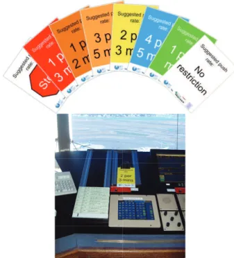
In 2010, color-coded cards were used to communicate suggested pushback rates to the air traffic controllers, thereby eliminating the need for verbal communications. One of eight
5” × 7.5” laminated cards, with pushback rate suggestions
to “Stop” (zero rate) and “No restriction” cards was used, as shown in Figure 2 (right). The deployment required two researchers in the Tower: One to collect the necessary in-puts for the algorithm, and one to evaluate the inin-puts and determine the appropriate pushback release rate. Once the pushback rate recommendation had been calculated (manually, using PRC v1 [5]), one of the researchers would place the appropriate color-coded card on the display in front of the Boston Gate Controller, for example 3 per 5 min, signifying that only 3 aircraft were recommended to be released every 5 minutes. Any aircraft beyond that would need to be held at the gate. The setup of the suggested rate card in the Boston Gate Controllers position is shown in Figure 2 (bottom). This manner of communicating the rate to the controller is referred to as the rate control display.
Fig. 2: (Top) Color-coded cards that were used to communicate the suggested pushback rates. (Bottom) Display of the color-coded card in the Boston Gate Controller’s position.
B. Tablet computers
In 2011, a more advanced DST was designed in order to implement Pushback Rate Control algorithms in the airport
tower environment. A particular goal was to develop a process that the controllers would (in principle) be able to imple-ment without the help of any researchers, which motivated a program which would generate the desired rate output given the necessary inputs. A device that enabled flexible and rapid prototyping was also desirable.
The device used was a 7” Samsung Galaxy TabTM tablet
computer with the AndroidTM operating system, which is
convenient for application development, while being compact and portable. Two tablet computers were used in the imple-mentation, namely, the rate control transmitter and the rate control receiver. Inputs were entered into the rate control transmitter, which then determined the optimal pushback rate and communicated it via a Bluetooth wireless link to the rate control receiver. As shown in Figure 3 (left), the receiver displayed the recommended rate to the Boston Gate Controller, who authorized aircraft to pushback.
!"#$%$&'#( )#"*+#%,( -"*./0( )$0$ ( 12302&( 4$0#( 4%2 5&6 ( !2& 0%2 "( 72'$"( !2&0%2"( 8#30( 72'$"( !2&0%2"( 9$30( 72 '$"( !2 & 0%2 "( :# "*'2 ; 0# %( <%$='( >$&$.#?#&0( !22%6*&$02%( @5;#%+*32%( Rate Control Receiver Rate Control Transmitter Bluetooth Connection
Fig. 3: (Left) Layout of the BOS ATCT, showing the setup of the rate control transmitter and receiver. (Right) Rate control transmitter, showing the input interface.
1) Inputs: The inputs to the rate control transmitter were the runway configuration, meteorological conditions, expected number of arrivals in the next 15 minutes, numbers of aircraft with jet engines under Ground Control and Local Control, and number of non-jet aircraft taxiing out. The input inter-face is shown in Figure 3 (right). The expected takeoff rate and the recommended pushback rate were then automatically
calculated by executing PRC v2 on the input device, and transmitted to rate control receiver.
The inputs only need to be updated every 15 minutes. They can all be determined by either looking at the flight data screen or by manually counting the number of flight strips on the Ground or Local Controller positions. Because these numbers are easy to determine, it is quite simple to update the inputs to the tablet.
2) Outputs: The receiver conveyed the suggested pushback rate to the Boston Gate Controller through one of two display modes: the rate control and the volume control displays.
a) Rate control display: The output in this mode was
a color-coded image of the suggested pushback rate, similar to the color-coded cards. In this display mode, the Boston Gate Controller keeps track of the time intervals and the number of aircraft that have already pushed back. When the rate of aircraft requesting pushback clearance exceeds the recommended pushback rate, aircraft are held at the gate until the next time interval. The Boston Gate Controller also keeps track of aircraft holds, and releases them at the appropriate time.
b) Volume control display: This display mode was
de-veloped to help the Boston Gate Controller keep track of the number of aircraft that had called for pushback, and that had already been released in that time-window. It is an alternative to the handwritten notes that controllers otherwise use to keep track of gate-holds. The volume control mode also provides visual cues of the passage of time, and upcoming actions. The volume control display was expected to reduce controller workload, and to possibly help merge the Boston Gate Controller position with another position.
On the volume control display, a 15-minute time-window is broken down into smaller time intervals. For example, if the rate is 3 per 5 minutes, the display shows three rows of three aircraft icons each, with each row corresponding to a 5-minute
Pushbacks in current time period can be released (grayed out) Unused rate carried over to the next time interval
Pushbacks can be reserved for later in the time period (angled)
Pushbacks can also be reserved for the next 15-min time period
Fig. 4: Volume control display mode.
time interval (illustrated in Figure 4). A time interval becomes active when the current time is within that time interval, and is indicated by a small black arrow to the left of the time interval. Aircraft can only be released during an active time interval, otherwise pusback positions can only be reserved. Any unused release slots in a given time interval roll over to the next time interval, up to a maximum of twice the rate. The following actions are available in the volume control display mode:
1) Releasing an aircraft: If a flight calls for push back and will be released, the controller selects one of the aircraft icons in the ongoing time interval. The color of the icon then changes from black to gray, indicating that it has been released.
2) Reserving a pushback spot: If a flight calls for push back and there are no more positions available in the current time interval, the Boston Gate Controller tells the aircraft to hold and reserves the next available spot. This is done by selecting the appropriate aircraft icon on the display, which then rotates by 45 degrees to indicate that it has been reserved. When that aircraft is eventually released, the controller selects the aircraft icon again; the icon then rotates back and turns gray.
pushback position for a future 15-minute time period can be reserved by touching the blank space next to that time period. A rotated aircraft icon then appears in order to indicate a reservation. When the corresponding time period arrives, that aircraft icon will appear as already reserved on the display. For example, in Figure 4, the rotated aircraft icon implies that the corresponding push-back position had been previously reserved for a flight, possibly because of a downstream traffic management constraint.
VI. DSTDEPLOYMENT AND TESTING
The demonstration at BOS consisted of 15 four-hour periods of metering: Eight periods with the color-coded cards and PRC v1 in 2010, and eight periods with the tablet computer DST and PRC v2 in 2011.
During the field trials at BOS in 2011, a member of the research team gathered and input data into the rate control transmitter. The rate control receiver was located next to the Boston Gate Controller, who chose between the rate control and volume control displays. It is expected that in a long-term deployment, the traffic management coordinator (TMC) or the tower supervisor would input the data. For a part of the field-tests, the Boston Gate position was merged with another position, either clearance delivery or the Traffic Management Coordinator to investigate the potential implementation of PRC without requiring an additional controller at the Boston Gate position.
The recommended rate is valid for the next 15 minutes, and then needs to be updated. The application reminds controllers when it is time to update the inputs and rerun the control algorithm to receive a new rate. Similarly, the rate control receiver is notified by a popup window that the rate has been updated.
A. Evaluation of the DST
After the field-tests at BOS had been completed, air traffic controllers in the ATCT were surveyed regarding their opin-ions on the study as a whole, and specifically on the imple-mentation and use of the DST. There were 21 respondents in all, 15 of whom filled the Boston Gate position in 2010 [5], 13 who did so in 2011, and 12 who did so in both years. The remaining respondents served in other positions in the BOS tower.
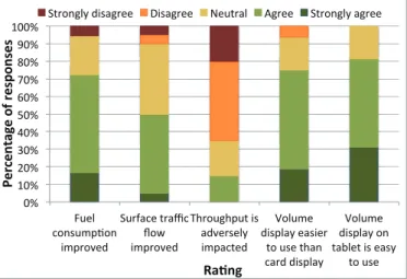
Quantitative ratings were solicited on five topics: Whether they thought fuel burn decreased, whether surface traffic flows improved, whether throughput was adversely impacted, whether the volume control display was easier to use than the rate control display (referred to as the “card display” after the color-coded cards used in 2010 [5]), and whether they found the volume control mode easy to use. The survey results, shown in Figure 5, demonstrate that the responses were generally positive, and that the controllers appreciated the DST. Several respondents who agreed that the throughput was adversely impacted also agreed that the surface traffic flow improved. This correlation, coupled with their overall positive comments, suggests that there may have been some confusion on the phrasing of this question, which was the only one for which a negative response implied better performance.
!"# $!"# %!"# &!"# '!"# (!"# )!"# *!"# +!"# ,!"# $!!"# -./0# 1234.56723# 85692:/;# <.9=>1/#?9>@1# A2B# 85692:/;# CD92.ED6.?#84# >;:/94/0F# 856>1?/;# G20.5/# ;8460>F#/>48/9# ?2#.4/#?D>3# 1>9;#;8460>F## G20.5/# ;8460>F#23# ?>H0/?#84#/>4F# ?2#.4/# !" #$ " % &' ( " )* +) #" ,-* % ," ,) .'/%()
<?923E0F#;84>E9//# I84>E9//# J/.?9>0# KE9//# <?923E0F#>E9//#
Fig. 5: Distribution of responses from air traffic controller survey regarding the PRC v2 DST at BOS.
Thirteen responses were also positive about combining Boston Gate and another position, removing the need for a dedicated controller during gate-holds. Ten of these responses suggested BOS Gate should be combined with Clearance Delivery, three indicated it should be combined with the Traffic Management Coordinator, and one person each voted for Ground Control and Flight Data (it was possible to select more than one possible position for the combination). Since the Clearance Delivery position would normally precede Ground Control (in the absence of BOS Gate), it is quite natural that it also adopt the responsibilities of BOS Gate. Secondly, unlike Ground Control, Clearance Delivery is not currently dealing with aircraft in the Active Movement Areas, and may be able to handle the additional workload, with decision support.
The write-in questions also revealed that the controllers liked the volume control display format. Comments on the best features of the DST included “the ability to touch planes”, “reserve spots”, “[ability to] count the planes and account for aircraft with long delays”, “allows me to push and tells me to hold”, and “easy to use and understand”. Suggestions for improvement include increasing the icon sizes and maintaining more pressure on the runway. In general, the controllers were satisfied with the modifications made between 2010 and 2011, with one of them remarking, “Liked the improvement in just one year”.
B. Impacts on operational performance
The benefits of pushback metering were significant, with over 23 US tons of fuel burn reduction over the two years. The methodology used in the benefits assessment has been described in prior work [5], [6]. In particular, the field-tests with the tablet DST showed that over eight four-hour periods, the estimated fuel savings were 9 US tons (2,650 US gallons), and the carbon dioxide emissions decreased by 29 US tons. Aircraft pushbacks were only delayed by 5.3 min on average.
C. Qualitative observations
1) Compatibility with traffic flow management initiatives: An important goal of this effort was to investigate the com-patibility of Pushback Rate Control with other traffic flow management initiatives. During highly convective weather, the abundance of these programs leads to many target departure times, schedule disruptions and flight cancellations. As a result, surface congestion often does not build up, and there is no need for gate-holds. However, there are exceptions to this general behavior, including two days during the PRC v2 field tests (Jul 18 and Jul 21, 2011). During these days, controllers demonstrated that they could handle airspace restrictions such as Minutes-In-Trail (MINIT) programs and target departure times (e.g., EDCTs) while executing the PRC v2 strategy. The integration of the MINIT restrictions with metering was simple: The total number of flights released per time window was set by the metering program, and the mix by the MINIT program. For example, if the recommended pushback rate were 3/5 min while westbound flights had 5 MINIT, the controller would release two flights with no MINIT restrictions along with a westbound departure, every 5 min. The field-tests also showed that if known in advance, delays due to controlled departure times could be efficiently absorbed as gate-holds.
2) Increased predictability: An additional benefit of the approach was the ability to communicate expected pushback times to pilots in advance. Once the suggested pushback rate was given to the controller at the start of each time-window, the controller communicated the expected release times to all aircraft on hold. These flights received their release times several minutes in advance, which was useful in planning ground resources.
3) Natural metering effect: The suggested pushback rate in very low congestion time-periods is 1 per min. However, when the Boston Gate position was merged with another position, it resulted in a natural rate of 1/min without explicit gateholds.
For example, when the Boston Gate position was merged with the Traffic Management Coordinator, after the controller cleared an aircraft that called for push, he/she would have to spend the rest of the minute for a traffic management task (such as, calling the center to obtain an Expected Departure Clearance Time). As a result, the next aircraft would only be released after a minute, resulting in a natural metering of 1 per min unless a lower rate was recommended.
D. Extensions
While the researchers or controllers manually input data in the prototype, the inputs could easily be obtained from a live surface surveillance data feed in the future, eliminating the need for a manual update every 15 minutes. Algorithms for such data processing have been investigated in prior work [15].
The control strategy and implementation approach also need to be adapted to different airport operating environments. Factors that need to be considered in the adaptation include operational procedures, airport layout, facility layout, demand characteristics, etc. [16].
VII. CONCLUSIONS
This paper demonstrated the implementation of an airport congestion control strategy, with minimal changes to current procedures and controller workload. A key contribution of this work was the identification of rate control strategies as being amenable to implementation by air traffic controllers in the current operating environment. Two modes of decision support were investigated: The first was based on color-coded cards that removed the need for verbal communications with the controller on duty; the second was a more advanced decision support tool built on tablet computers. An application for the tablet computer was also developed to automate the task of determining the recommended pushback rate, and to assist the
air traffic controllers in keeping track of the pushback rate as well as additional gate-hold constraints. A survey of the air traffic controllers showed that decision support tool was very well-received.
ACKNOWLEDGMENTS
The demonstration was made possible by Brendan Reilly, Deborah James, Pat Hennessy, John Ingaharro, John Melecio, Michael Nelson and Chris Quigley at the BOS Facility; Vincent Cardillo, Flavio Leo and Robert Lynch at Massport; and the Air Transport Association. Regina Clewlow and Diana Pfeil conducted observations of BOS tower procedures. Vivek Panyam (University of Pennsylvania) volun-teered his effort in the development of the Android tablet application. Harshad Khadikar (MIT) participated in tower observations before and during the trials, and also analyzed the ASDE-X data. We thank Steve Urlass and Lourdes Maurice at the FAA for their support, and James Kuchar and Jim Eggert of MIT Lincoln Laboratory for their support and help with the ASDE-X data.
REFERENCES
[1] K. N. Yu, Y. P. Cheung, T. Cheung, and R. C. Henry, “Identifying the impact of large urban airports on local air quality by nonparametric regression,” Atmospheric Environment, vol. 38, no. 27, pp. 4501–4507, 2004.
[2] D. C. Carslaw, S. D. Beevers, K. Ropkins, and M. C. Bell, “Detecting and quantifying aircraft and other on-airport contributions to ambient nitrogen oxides in the vicinity of a large international airport,” Atmo-spheric Environment, vol. 40, no. 28, pp. 5424–5434, 2006.
[3] M. A. Miracolo, C. J. Hennigan, M. Ranjan, N. T. Nguyen, T. D. Gordon, E. M. Lipsky, A. A. Presto, N. M. Donahue, and A. L. Robinson, “Secondary aerosol formation from photochemical aging of aircraft exhaust in a smog chamber,” Atmospheric Chemistry and Physics, vol. 11, no. 9, pp. 4025–4610, 2011.
[4] S. H. Yim, M. E. Stettler, and S. R. Barrett, “Air quality and public health impacts of UK airports. Part II: Impacts and policy assessment,” Atmospheric Environment, vol. 67, pp. 184–192, 2013.
[5] I. Simaiakis, H. Balakrishnan, H. Khadilkar, T. Reynolds, R. Hansman, B. Reilly, and S. Urlass, “Demonstration of Reduced Airport Congestion Through Pushback Rate Control,” in 9th Eurocontrol/FAA ATM R&D Seminar, 2011.
[6] I. Simaiakis and H. Balakrishnan, “Dynamic control of airport depar-tures: Algorithm development and field evaluation,” in American Control Conference, 2012.
[7] E. R. Feron, R. J. Hansman, A. R. Odoni, R. B. Cots, B. Delcaire, W. D. Hall, H. R. Idris, A. Muharremoglu, and N. Pujet, “The Departure Plan-ner: A conceptual discussion,” Massachusetts Institute of Technology, Tech. Rep., 1997.
[8] P. Burgain, E. Feron, and J.-P. Clarke, “Collaborative Virtual Queue: Fair Management of Congested Departure Operations and Benefit Analysis,” Air Traffic Control Quarterly, vol. 17, no. 2, 2009.
[9] F. Carr, A. Evans, E. Feron, and J. Clarke, “Software tools to support research on airport departure planning,” in Digital Avionics Systems Conference. Irvine CA: IEEE, 2002.
[10] F. Carr, “Stochastic modeling and control of airport surface traffic,” Master’s thesis, Massachusetts Institute of Technology, 2001. [11] N. Pujet, B. Delcaire, and E. Feron, “Input-output modeling and control
of the departure process of congested airports,” AIAA Guidance, Naviga-tion, and Control Conference and Exhibit, Portland, OR, pp. 1835–1852, 1999.
[12] I. Simaiakis and H. Balakrishnan, “Queuing Models of Airport Departure Processes for Emissions Reduction,” in AIAA Guidance, Navigation and Control Conference and Exhibit, 2009.
[13] R. Clewlow and D. Michalek, “Logan Control Tower: Controller Posi-tions, Processes, and Decision Support Systems,” Massachusetts Institute of Technology, Tech. Rep., 2010.
[14] I. Simaiakis and H. Balakrishnan, “Departure throughput study for Boston Logan International Airport,” Massachusetts Institute of Tech-nology, Tech. Rep., 2011, No. ICAT-2011-1.
[15] M. Sandberg, “Applications of ASDE-X Data to the Analysis of Airport Surface Operations,” Master’s thesis, Massachusetts Institute of Tech-nology, 2012.
[16] M. Sandberg, T. G. Reynolds, H. Khadilkar, and H. Balakrishnan, “Airport Characterization for the Adaptation of Surface Congestion Man-agement Approaches,” in 10th Eurocontrol/FAA ATM R&D Seminar, 2013.