Delivering Real-Time Holographic Video Content With Off-The-Shelf PC Hardware
by
Tyeler Quentmeyer
Submitted to the Department of Electrical Engineering and Computer Science in Partial Fulfillment of the Requirements for the Degrees of
Bachelor of Science in Computer Science and Engineering
and Master of Engineering in Electrical Engineering and Computer Science at the Massachusetts Institute of Technology
May 5, 2004 > a ZC72
J
Copyright 2004 Massachusetts Institute of Technology. All rights reserved.
Tyeler S. Quentmeyer Department of Electrical Engineering and Computer Science May 5, 2004
Certified by
Accepted by
V. Michael Bove, Jr. Principal Research Scientist Program in Media Arts and Sciences Thesis Supervisor
Arthur C. Smith Author
Delivering Real-Time Holographic Video Content With Off-The-Shelf PC Hardware
by
Tyeler S. Quentmeyer Submitted to the
Department of Electrical Engineering and Computer Science May 5, 2004
In Partial Fulfillment of the Requirements for the Degree of Bachelor of Science in Computer Science and Engineering
and Master of Engineering in Electrical Engineering and Computer Science ABSTRACT
We present a PC based system to simultaneously compute real-time holographic video content and to serve as a framebuffer to drive a holographic video display. Our system uses only 3 PCs each equipped with an nVidia Quadro FX 3000G video card. It replaces a SGI Onyx and the custom built Cheops Image Processing System that previously served as the platform driving the MIT second-generation Holovideo display. With a prototype content generation implementation, we compute holographic stereograms and
update the display at a rate of roughly 2 frames per second.
Thesis Supervisor: V. Michael Bove, Jr. Title: Principal Research Scientist
ACKNOWLEDGEMENTS
First, I would like to acknowledge my original thesis advisor, Stephen Benton, and dedicate my work to him. His vision for holographic displays and work in holography defined the field and made all of my work possible. His work will always be an inspiration.
I am most grateful to my thesis advisor, Mike Bove. The fundamental idea behind this project was his own. He was a valuable source of information about Holovideo and Cheops. I am very thankful that he assumed supervision of my work and provided much needed leadership. Without his guidance and support, I would not have been able to achieve my goals.
I would like to thank everyone in the Spatial Imaging group, past and present, particularly Wendy Plesniak, Steve Smith, Pierre St.-Hilaire, and Sam Hill. Wendy was a wonderful source of information about Holovideo and an invaluable collaborator in hologram computation. I would like to thank Steve for helping get this project off the ground, for his guidance and input, for assuming leadership of the group, and for helping take photographs and make movies. I would like to thank Pierre for building the display on which my work was based and for his input about working with the system. I would like to thank Sam for his input, for helping take photographs, and for helping me maintain my sanity.
Thanks also to Won Chun and Joe Duncan. Won was a great source of information about OpenGL, optimizing my rendering algorithms, and 3D software in general. Joe provided helpful information about some of the electrical underpinnings of the system.
Finally, I would like to thank my parents, Steve and Becky Quentmeyer, for their lifelong encouragement. Without their support and guidance, I would not have made it this far.
TABLE OF CONTENTS
1 IN TRO DUC TIO N ... 7
1.1 MOTIVATION FOR IMPROVING 3D DISPLAY TECHNOLOGY...7
1.2 THE MIT SECOND-GENERATION HOLOVIDEO SYSTEM ... 9
1.3 MOTIVATION FOR PC PLATFORM TO DRIVE HOLOVIDEO... 10
1.4 OUTLINE OF THESIS ... 11
2 H O LO V IDEO SPECIFICA TIO N S ... 13
2.1 INTRODUCTION... 13
2.2 H OLOVIDEO OVERVIEW ... 13
2.3 OUTPUT CHARACTERISTICS ... 16
2.3.1.1 Im age size and view zone... 16
2.3.2 Resolution...16
2.4 INPUTS ... 16
2.4.1 H orizontal sync signal... 17
2.4.2 Vertical sync signal... 17
2.4.3 D ata inputs ... 17
2.4.3.1 H ologram data form at ... 18
2.4.4 H orizontal scanning signal generator ... 18
2.4.4.1 Frequency ... 19
2.4.4.2 Phase... 19
3 COMPUTING HOLOGRAMS ... 20
3.1 INTRODUCTION... 20
3.2 OPTICALLY GENERATED HOLOGRAM S ... 20
3.3 INTERFERENCE HOLOGRAM S ... 22
3.4 D IFFRACTION SPECIFIC HOLOGRAM S ... 24
3.4.1 H o gel-Vector encoding ... 26
4 CHEOPS... .... ... ... 29
4.1 SYSTEM OVERVIEW ... 29
4.2 PROCESSOR MODULE... 30
4.3 OUTPUT MODULES... 2
4.3.1 Fram ebuffer specifications... 33
4.4 SPLOTCH ENGINE ... 33
4.4.1 H ologram computation speeds... 34
5 USING PCS TO DRIVE HOLOVIDEO ... 36
5.1 INTRODUCTION... 36
5.2 SYSTEM OVERVIEW ... 36
5.3.2 Choice of video card ... 37
5.3.3 nVidia Quadro FX 3000G output specifications... 38
5.3.3.1 Synchronizing outputs... 38
5.3.3.1.1 Genlock ... 38
5.3.3.1.2 Frame lock... 39
5.3.3.2 Video mode limitations ... 39
5.3.3.2.1 Video mode background ... 39
5.3.3.2.2 Limitations ... 41
5.3.4 Constructing 18 synchronized data outputs... 42
5.3.5 Video mode ... 42
5.3.5.1 Hologram framebuffer data format ... 45
5.4 HORIZONTAL SYNC INPUT ... 47
5.4.1 Requirements from Holovideo...47
5.4.2 Driving the horizontal sync input... 48
5.5 VERTICAL SYNC INPUT ... 48
5.5.1 Requirements from Holovideo... 48
5.5.2 Driving the vertical sync input... 48
6 USING PCS TO COMPUTE HOLOGRAMS ... 49
6.1 INTRODUCTION... 49
6.2 REQUIREMENTS ... 49
6.2.1 Requirements from Holovideo...49
6.2.2 Requirements from hologram computation algorithms ... 50
6.3 PREVIOUS WORK ... 50
6.3.1 Accumulation buffer based holographic stereogram computation... 51
6.3.2 High precision computing with commodity video cards ... 51
6.4 PLATFORM COMPUTATIONAL CAPABILITIES ... 52
6.4.1 System overview ... 52
6.4.1.1 Bandwidth considerations ... 53
6.4.2 nVidia Quadro FX 3000G capabilities ... 54
6.4.2.1 Programmable vertex and fragment processors ... 54
6.4.2.1.1 Traditional OpenGL pipeline background ... 54
6.4.2.1.2 CineFX 2.0 Engine ... 54
6.4.2.2 Capabilities... 55
6.5 USING THE GPU TO COMPUTE HOLOGRAMS... 56
6.5.1 Comparison to Cheops... 56
6.5.2 Accumulation buffer algorithm to compute holograms... 57
6.5.2.1 Rendering synchronization... 57
6.5.2.2 Hologram computation... 58
6.5.2.2.1 Optimizations ... 59
7.1.2.2 General comparison...63 7.2 HOLOGRAM COMPUTATION ... 65 7.2.] Computation speeds ... 65 8 FUTURE W ORK ... 67 8.1 REPLACE RF HARDWARE...67 8.2 HOLOGRAM COMPUTATION...69 8.2.1 Optimizations ... 69 8.2.2 RIP/RIS holograms... 69
8.3 IMPROVING IMAGE QUALITY... 71
8.3.1 Remove horizontal blanking... 71
8.3.2 Improve genlock/frame lock ... 72
9 CONCLUSION ... 73
10
APPENDIX A: HORIZONTAL SYNC CONVERTER CIRCUIT ... 741 INTRODUCTION
1.1
Motivation for improving 3D display technology
The proliferation of computing devices and increasingly complex electronic data in our daily lives is driving the need for effective visualization tools. The importance of understanding and manipulating three-dimensional data sets goes without saying in a number of fields such as computer-aided design, engineering, medical imaging, navigation, and scientific research. Possible applications for a three-dimensional visual experience to the arts and entertainment industry are endless. The motivation for improving display and content creation systems is overwhelming.
Although CPU speeds have been increasing exponentially with Moore's law, display technology has stagnated. In fact, it has been the slowest improving technology in the computing industry. Relative to CPU speeds, display technology has changed very little since the introduction of the television tube. CRT monitors have given way to LCDs and screen resolutions have seen improvements, but the fundamental experience has changed little since the advent of computing.
The typical 2D monitor used to interface with digital data sets only takes advantage of a small fraction of the amount of information that can be processed by the human visual
of stereo vision. Humans rely on depth cues to understand 3D data that are not provided by 2D displays.
Understanding 3D data sets is an important task. To put the mission in perspective, consider a few applications in medical imaging. MRI scans have the ability to collect enormous amounts of data about a patient. The data is usually presented in the form of thousands of 2D slices, making it very difficult for doctors to first find areas of interest and then to develop a coherent 3D understanding of the information at hand. MRI data is relied on for a number of tasks including identifying brain lesions, tumors, and internal trauma and for planning surgical procedures. Additionally, MRI capture technology is improving much faster than our ability to display it. This means that although we can get better pictures of the innards of the human body that in principle lead to better health care, we are limited by the ability of doctors to interact with and understand the massive amounts of data gathered by MRI technology.
Consider another compelling application of 3D imaging proposed by Plesniak [16]. If we couple a 3D display with a force feedback device, we not only allow the user to visualize a 3D data set but also to feel and natively manipulate that data set. By coupling a haptic device with three-dimensional display technology, we can build a system where a doctor can practice surgical procedures using a force feedback scalpel on a computer simulated holographic patient.
1.2 The MIT second-generation Holovideo system
The MIT second-generation Holovideo system is a real-time electro-holographic display. The end result of the system is a single-color horizontal parallax only (HPO) holographic image that is updated at video speeds. The three-dimensional image fills a volume 150mm wide, 75mm high, and 160mm deep, is visible over a range of 30 degrees, and is refreshed 30 times per second [1]. The system is made up of three components: the display (Holovideo), a framebuffer with stream-processing capabilities to serve holograms to the display (Cheops), and a computation platform to compute holographic data to be shown on the display (SGI Onyx).
(Rtg~Framebuifa
SG nxCheops
b dQ
SGI )1YXfrarmbuffer display
Cmrpessd Fringe Pttern Lktnrrprmsed Fringe Patton Figure 1: Overview of the MIT second-generation Holovideo system.
Holovideo is a display that inputs a 36MB computed holographic fringe pattern and outputs a reconstructed holographic image 30 times per second. The display reads its input over a custom 18-channel parallel connection. We will discuss Holovideo in more
The Cheops Image Processing System is a framebuffer with special purpose embedded stream-processing capabilities. It reads program instructions for its processors over a SCSI-2 bus and reads fringe pattern data directly into memory over a HIPPI bus. Cheops then runs the uploaded program on its stream-processors and fills its framebuffer memory with a holographic fringe pattern. The framebuffer is connected to Holovideo via the custom 18-channel parallel connection. Cheops is discussed in more detail in Chapter 4. [5][21]
The SGI Onyx is a general-purpose computing platform used to compute compressed holographic content that is loaded into Cheops and displayed by Holovideo. The SGI is not used to directly feed Holovideo for two reasons. First, Holovideo's high bandwidth requirements (36MB/frame * 30 frames/second) make it impossible. Second, the decompression algorithm run by Cheops is in fact a post-processing step that would have to be run on the SGI anyways. Cheops stream-processors not only alleviate the SGI of this extra step, but perform it faster than the SGI could. Each compressed fringe pattern is uploaded to Cheops, uncompressed, sent to Holovideo, and finally displayed as a three-dimensional image. [2][5]
1.3 Motivation for PC platform to drive Holovideo
There is a substantial amount of motivation to remove the SGI Onyx and the Cheops framebuffer from the Holovideo system. The Onyx is an outdated machine that is difficult to upgrade and difficult to replace without affecting the system. It has been prone to failure and requires a $6,000 annual service contract ($15,000 before a $9,000
educational discount) to keep it up and running. The Cheops system has proven very reliable but was custom designed and built. It is therefore virtually impossible to upgrade without rebuilding the entire system. In the event of its eventual failure, it is also extremely difficult to replace.
Off the shelf PCs and video cards seem to be an ideal replacement for the SGI and Cheops. PCs can replace the Onyx and Cheops to both compute holograms and to serve as a framebuffer for Holovideo. Modern video cards are incorporating a rendering pipeline that is sophisticated enough to implement certain holographic rendering algorithms. The high demand for and the high volume in which they are produced ensure that PC components are cheap, reliable, and easy to replace. They can be swapped out and upgraded seamlessly when new technology becomes available. PC CPU speeds improve with Moore's law and PC video card speeds improve at three times Moore's law. In this way, the system driving Holovideo can improve in speed, reliability, and cost effectiveness at the same rate as the market for off the shelf PC components.
1.4 Outline of thesis
The goal of this thesis is to build a platform to serve as a framebuffer for holographic video display systems, particularly the MIT second-generation Holovideo system, that is also capable of computing holographic content in as close to real-time as possible. We want to completely remove dependence on the SGI Onyx and Cheops Image Processing
serving as a framebuffer for Holovideo and is capable of computing holograms for Holovideo and writing them to the framebuffer at rates as close to smooth video frame rates as possible.
The next three chapters outline and give details about the systems we need to understand in order to achieve our goals. Chapter 2 discusses the Holovideo display at the level in which we need to understand it - mostly in terms of its inputs and outputs. Chapter 3 discusses how holograms are constructed, beginning with a very brief introduction to optical holography and then introducing computed holograms with emphasis on diffraction specific hologram. Chapter 4 describes the architecture and capabilities of the Cheops system that we are trying to replace.
The following two chapters introduce the bulk of the work for this thesis. Chapter 5 gives an overview of the PC architecture we introduce to drive Holovideo. It then gives details about how our PC system serves as a framebuffer for Holovideo. Chapter 6 discusses how our PC system can be used to compute holograms. It includes a discussion of the computational capabilities of our system and the description of a prototype implementation to compute diffraction specific holograms in real-time.
The final three chapters conclude this thesis document. Chapter 7 gives the results of our project, including a discussion of the image quality we produce and of the computation speeds we were able to achieve. Chapter 8 gives a few directions for future work and Chapter 9 offers a few concluding remarks.
2 HOLOVIDEO SPECIFICATIONS
2.1 Introduction
In this chapter, we give a brief overview of the MIT second-generation Holovideo display and a detailed specification for its inputs. For complete details, see Pierre St. Hilaire's doctoral dissertation [1]. Note that although our PC hologram computation and delivery platform is not specific to this holographic video display, future displays are likely to require similar inputs so we use Holovideo as a concrete example and proof of concept.
2.2 Holovideo Overview
A holographic display uses a computed fringe pattern to modulate light and produce a three-dimensional image. The crux of holographic video is the spatial light modulator (SLM), a device that modulates light with a computed fringe. Holovideo uses two cross-fired 18-channel acousto-optic modulators (AOMs) as the SLM and a chain of optics and scanning mirrors to construct a horizontal parallax only (HPO) hologram at video frame rates. The output of Holovideo is 144 vertically stacked horizontal lines, each of which is a thin HPO hologram (called a hololine), which are updated in real-time.
LaserVica
MnAC
Figure 2: Overview of the Holovideo display architecture.
Mrampff
Waus
Fringe patterns for the hololines in analog format are read from some storage unit (Cheops in the old system and the PC framebuffer in the new system) in groups of 18 and passed to Holovideo's 18 data input channels. Each fringe is then passed to a radio frequency (RF) process unit that frequency shifts the fringe to the AOM's desired frequency range. From there, the fringe is input in to one of the AOM's 18 input channels. Each output from the AOM is then passed to a system of scanning mirrors that steers the modulated light to the correct horizontal and vertical position. Finally, the diffracted light is imaged on a vertical diffuser at the output of the display. In this way, 18 hololines are imaged in one step. The process is repeated 8 times, until all 144 hololines are imaged.
18 Horizontal Lines
18 Horizontal Lines
18 Horizontal Lines
1
18 Horizontal Lines
Figure 3: The boustrophedonic scanning pattern used by Holovideo to draw lines to the image plane.
Mewa cd
The system of mirrors that steers the modulated light consists of a vertical scanning system and a horizontal scanning system. On input of the first set of 18 fringe patterns, the horizontal scanning system steers the fringe pattern from left to right over the horizontal range of the image. On the next set of inputs, the horizontal scanning system steers the fringe pattern in the opposite direction, from right to left. This boustrophedonic pattern removes the need for a horizontal retrace and thereby eliminates wasted time between horizontal scans. However, it also means that every other fringe pattern is imaged backwards and therefore needs to be fed into Holovideo in reverse order. The vertical scanning system lays down fringe patterns from top to bottom for each frame.
Between frames, the vertical scanning mirror needs to return to its starting position. In order to allow it to do so, there is a vertical retrace time between frames equal to one complete horizontal scan (left to right and back to left). Between horizontal lines, the horizontal scanning mirrors need to slow to a stop and accelerate to their scanning velocity in the opposite direction. While the horizontal mirrors are imaging lines, they need to move at a constant velocity to avoid distorting the image data. The horizontal mirrors therefore cannot be used to image data while they are nonlinearly changing directions. To compensate for this, there is a horizontal blanking period between fringe patterns on each data line of roughly 0.9ms. This value was determined empirically. For the display's scanning geometry, each horizontal line is scanned in a total of 3.3ms, giving a blanking period of about 27.27 percent.
2.3 Output characteristics 2.3.1.1 Image size and view zone
Holovideo's holographic output images into a view zone 150mm wide, 75mm high, and 160mm deep. (The depth of the view zone is in principle limited only by the amount of astigmatism that the human eye can tolerate at a typical viewing distance, 300mm. However, in practice, the 160mm depth figure is accurate.) The horizontal viewing angle - the angle from which the viewer can see the image - is 30 degrees.
2.3.2 Resolution
Each fringe pattern is 218 (256K) samples in length laid down over the 150mm wide image zone, giving a horizontal resolution of 256K/150mm = 1,748 samples per millimeter. The horizontal resolution is high enough to diffract light without artifacts visible to the human eye. There are 144 vertical lines over the 75mm high image zone, giving 2 lines per millimeter, equivalent to a 19" NTSC display. The value of 256K samples was chosen because it is easy to provide with the Cheops framebuffer and because it provides a data frequency suitable to the display characteristics.
2.4 Inputs
To understand the inputs to Holovideo, imagine that the fringe patterns are being stored in 18 parallel video framebuffers. Each fringe pattern is on one horizontal line. Therefore each framebuffer provides 8 horizontal lines per vertical refresh.
2.4.1 Horizontal sync signal
Holovideo reads in a horizontal sync signal from our imaginary framebuffer. A rising edge should coincide with the start of a new fringe pattern on the data inputs (a phase delay between the fringe pattern location and the horizontal sync pulse is set on a signal generator as described in 2.4.4.2). The width of the pulse is ignored - only the rising edge is used.
2.4.2 Vertical sync signal
Holovideo also reads in a vertical sync signal from our imaginary framebuffer. For a particular frame, a rising edge should coincide with the end of the last fringe pattern's horizontal blanking period and therefore the beginning of the vertical retrace period. Although the width of the pulse is ignored, it must be of size less than one horizontal sync period. Following the rising edge of the vertical sync signal, the next two horizontal sync periods should not contain fringe patterns.
2.4.3 Data inputs
Holovideo has 18 data input channels. Each input channel reads an analog signal corresponding to fringe patterns at a frequency dictated by the horizontal sync signal. Each fringe pattern should consist of 256K samples followed by a blank period determined by the system's horizontal blanking period. Each data channel should be driven with a series of 8 fringe patterns, followed by 2 blank fringe patterns. The 8 used
beginning with left-to-right. That is, the first fringe should correspond to an image from left to right, the second fringe should correspond to an image from right to left, et cetera.
2.4.3.1 Hologram data format
The time multiplexed fringe patterns from the 18 data input channels are combined by Holovideo to create a single frame of an image as follows: The first fringe from the first input is mapped to the first horizontal line of the image output, the first fringe from the second input is mapped to the second line, the first fringe from the third input to the third line, et cetera. Then, the second fringe from the first input is mapped to the 1 9th line, the second fringe from the second input to the 2 0th line, the second fringe from the third input to the 2 1st line, and so on.
1st fringe from 1st input
1st fringe from 2nd input
El
1st fringe from 3rd input SV S
1 st fringe from 16th input 1st fringe from 17th input
1st fringe from 18th input
2ndfrin/efrom istinput
2nd fringe from 2nd input 2nd fringe from 3rd input
Figure4: Themappigfromfringepattens orn trhm 1rd nparlenustthelnsdano h
Figure 4: The mapping from fringe patterns on the 18 parallel inputs to the lines drawn on the
screen.
2.4.4 Horizontal scanning signal generator
The horizontal scanning system of Holovideo is driven with a signal generator that produces a triangle wave. The beginning of the triangle wave coincides with the
beginning of the left-to-right scan, the peak coincides with the end of the left-to-right scan and the beginning of the right-to-left scan, and the end coincides with the end of the right-to-left scan. The start of a triangle wave period is triggered by the horizontal sync signal input. Strictly speaking, the horizontal scanning signal generator is part of the scanning system and not an input. However, the triangle wave generated by the signal generator has properties that must be set by hand to match the data input system.
2.4.4.1 Frequency
The frequency of the triangle wave generated by the signal generator should be twice the frequency of horizontal sync pulses.
2.4.4.2 Phase
The phase of the triangle wave generated by the signal generator should be set to match the offset of the rising edge of the horizontal sync pulse and the start of a fringe pattern on the data channels.
3 COMPUTING HOLOGRAMS
3.1 Introduction
In this chapter, we give a cursory background on traditional optically generated holograms and on synthetically generated computed holograms. We begin with an overview of the simplest optically generated hologram. We then introduce computationally generated holograms through interference modeling. Finally, we introduce Lucente's diffraction specific holographic stereogram and the Hogel-Vector compressed encoding thereof.
3.2 Optically generated holograms
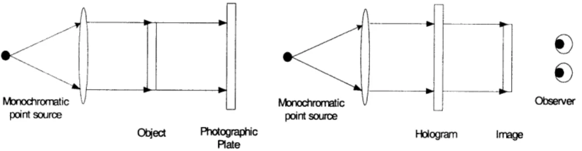
The simplest hologram to describe is the in-line (Gabor) hologram. This method is limited to creating a hologram of a translucent image located on a transparency, yet it serves as a useful example. A transparency prepared with a translucent image to be turned into a hologram is illuminated head-on with a collimated light source. The diffracted light pattern is then recorded on a photographic plate located opposite the transparency. When the photographic plate is later illuminated with the same light source used in the recording process, an image of the transparency appears to float in space. [7]
Monodhrormtic
V
Monochromatic v Obseverpoint source point source
Otect Photographic Hologram Image Plate
Figure 5: The in-line hologram setup. The first image is the setup used to create the hologram and the second is the setup used to view the hologram.
The photographic plate records the intensity of the impending electric field at each point. There are two parts to this field: one from the light source and one from the light interacting with the object. The collimated monochromatic light source provides a simple plane wave traveling orthogonally towards the transparency.
Esource = Epiane = e i(krwt)
Light from the source reflects off the object and provides some complicated field depending on the shape and surface properties of the object.
Eobject = f(r)
At the photographic plate, the electric field is the superposition of the two fields and the intensity is the modulus squared. The intensity at the plate is called the diffraction pattern or the fringe pattern of the object.
Ihologram = IEsource + Eobject12
Later, when the photographic plate is again lit with the source, the light interacts with the recorded fringe pattern to approximately reconstruct the electric field that would be present if the object itself was being illuminated by the light source.
There are two major differences between the in-line hologram and more general methods. First, the light source plane wave (typically called the reference beam) is usually tipped at some angle 0 with respect to the photographic plate. Second, the object to be imaged is usually three-dimensional rather than a flat transparency. The hologram is, however, still just the diffraction pattern from a plane wave and some object.
3.3 Interference holograms
Although the simple setup described above is far from state of the art, optically generated holograms will always be limited to static representations of objects that actually exist and are practical to manipulate in a controlled laboratory setting. We would have a very hard time, for example, making a traditional hologram of the Eiffel tower or a holographic movie of a ball bouncing.
Since a hologram is just a photographically recorded diffraction pattern, it is easy to model the process computationally and print a computer generated diffraction pattern. Rather than simulate the light source interacting with the object, we can model the object as a densely packed skin of analytically defined light emitters and simply compute the superposition of the reference beam and each of the object's emitters. The simplest type of emitter is the spherical emitter, which outputs light uniformly in all directions.
Espherical - Aei(kI-rol-wt) The field at the photographic plate is then just
where Eobjec, is the sum of the emitter fields (the field from the object). This gives an intensity of
I = |Etotal|2 = |Eobject|2
+ |Ereferencel2 + 2ReEojet*Ereerence}
This intensity value is calculated over the entire discretized photographic plate and output using the equivalent of a very high quality printer and then lit in the same way as a normal hologram.
This approach to computing holograms was pioneered and successfully demonstrated by Leseberg in 1986 [9]. Higher quality images using the same basic principles were demonstrated by Underkoffler [22]. Holograms computed using the interference method are some of the highest quality computer generated holograms made to date. They are, unfortunately, also very slow to compute.
Interference computed holograms are high quality and in a sense the best holograms that a digital system can generate. They are, however, slow to compute. For an object consisting of 10,000 spherical emitters and our 36 megasample display, interference computation will take at least 5 trillion floating-point operations. To compute the thirty holograms per second necessary to generate dynamic content, we would need a computing system capable of 60 trillion flops - far from feasible with existing hardware. [2]
3.4 Diffraction specific holograms
The inspiration for diffraction-specific computation of holograms comes from examining the functional role of the fringe pattern. When a light source impinges on the fringe pattern, the light from the source is diffracted in some direction. The job of the fringe pattern, then, is to diffract light in a particular direction. As it turns out, the angle at which light is diffracted is a simple function of the spatial frequency of the fringes. If we want to diffract light at some angle 0, all we have to do is output a fringe pattern with spatial frequency f(0). A fringe pattern that does this is called a basis fringe. The intensity of the light diffracted by a basis fringe can be manipulated by scaling the amplitude of the fringe. [2] [19]
We want to fill the view volume with light in every direction, so the fringe pattern is obviously more than a single basis fringe. Since we are constructing a three-dimensional image, the light you see when you look at the display from one direction should be different from the light you see in another direction (i.e., the object should exhibit parallax as you move your head from left to right). Let the intensity of light you see from angle 0 be called WO. We want to construct a fringe that diffracts Wo light into angle 0 for all 0. The fringe to do-this is
fringe = WO * basis
9
0
If we were to fill each hololine with one fringe pattern computed in this way, the image would always be a single color at each angle. We want to divide the hologram into
subregions of some vertical and horizontal extent. In our case, we use vertical stripes.
This way, at any given angle, each vertical stripe contributes a single color for some discrete horizontal region. One of these bars for a single horizontal line is called a holographic element, or hogel for short. The composite image is then much like a normal
digital image built-up from a number of uniformly colored pixels. A typical
configuration for the Holovideo display is to divide each horizontal line into hogels 1,024 samples long. Since a horizontal line is made up of 262,144 samples, there are 256
hogels per hololine.
The equation describing a fringe pattern as the weighted sum of basis fringes given above is in terms of a continuous viewing angle parameter, . The Holovideo display is digital so we must discretize 9. After examining the optical properties of the display and the human visual system, a typical value of 32 discrete viewing angles over a range of thirty degrees is used. This means that the range of angles at which the display can be viewed is thirty degrees (fifteen degrees to the left or right). In that arc, 32 distinct images are displayed at evenly spaced angular increments. Since there are 32 angular regions, we need 32 basis fringes. Each basis fringe is now responsible for diffracting light over a small angular increment so is redefined to contain all spatial frequencies that map to angles within its increment.
standard computer graphics method. For each horizontal line, each hogel is then computed using the equation given above for a fringe in terms of weights and basis fringes where each weight is the corresponding pixel value from one of the 32 rendered images. The complete horizontal line is 256 sequential hogels and the complete hologram is 144 stacked lines. By using a discrete set of images and view zones to approximate a continuous optical phenomenon, we are constructing what is called a holographic stereogram [17].
3.4.1 Hogel-Vector encoding
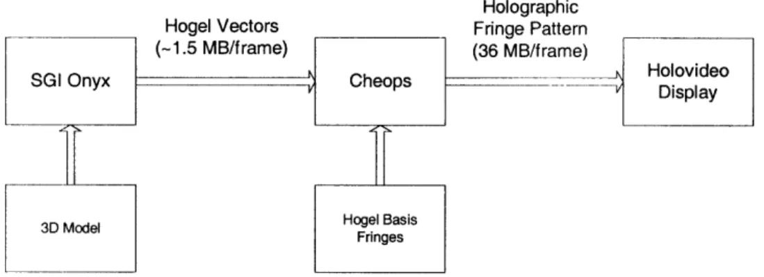
The current Holovideo display is configured with a HIPPI bus connecting the Cheops framebuffer and a SGI Onyx workstation. The amount of data that can be transferred from the Onyx to Cheops is therefore limited by the bandwidth of the HIPPI bus. Sending a fully computed fringe pattern of 36 MB 30 times per second would require over 1GB/s of bandwidth. Since the HIPPI bus runs at 100MB/s, we need a way of compressing a fringe pattern by at least a factor of ten in order to achieve video frame rates. Cheops must be capable of constructing the full fringe pattern from the compressed form. [2]
Holographic
Hogel Vectors Fringe Pattern
(-1.5 MB/frame) (36 MB/frame)
__G____nyx_ Ch_ e _ps __ sHolovideo
SGI Onyx Cheops - Display
3D Model Hogel BasisFringes
Figure 6: The flow of hologram data using Hogel-Vector encoding.
Rather than compute the fringe pattern at each hogel, we can express all of the required information in terms of the basis fringes and the weights. We organize the corresponding weights from each rendered image in each hogel into a vector called a Hogel-Vector. For example, the Hogel-Vector for the 17th hogel contains the color value from the 17th pixel of each of the 32 rendered views. We organize the basis fringes into a set of vectors with one vector for each sample in a basis fringe (for a total of 1,024 vectors). The basis fringe vector for a sample point contains the sample value from each of the 32 basis fringes corresponding that sample point. For example, the 5 6 7th basis fringe vector contains the 56 7th sample of each of the 32 basis fringes. The ith sample of a fringe pattern is then calculated as
fringei = hogel vector * basis fringe vectori
Since the basis fringes never change, we can send them to Cheops at system initialization. For each holographic frame, then, we only need to send the Vectors. Each
Hogel-real time. The compression format is lossless and simple enough that the Splotch Engines on Cheops are capable of constructing the uncompressed holograms from the Hogel-Vector encoded format.
4
CHEOPS
4.1 System Overview
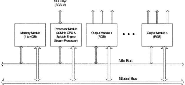
The Cheops Image Processing System is a block data-flow parallel processor originally designed for research into scalable digital television at the MIT Media Lab. A custom Cheops configuration was built primarily to serve as a framebuffer to feed holographic fringe patterns to Holovideo. Its secondary purpose is to provide high-speed custom computational power to aid in computing fringe patterns. [5][21]
Cheops is a modular system that connects input modules, output modules, and computational blocks. These modules are connected through two busses: The first, the Global Bus, is a 32-bit wide bus designed for transferring control instructions at rates up to 32 MB/s. The second, the Nile Bus, is designed for transferring large blocks of 24-bit wide data at sustained rates of 120 MB/s.
SGI Onyx
(SCSI-2)
Processor Module
Memory Module (32MHz CPU & Output Module 1
(1 to 4GB) Splotch Engine (RGB) Stream Processor) A I -N S 0 . Nile Bus Global Bus Output Module 6 (RGB) V
Figure 7: The Cheops configuration used to drive Holovideo.
The configuration used for the MIT second-generation Holovideo system has 6 output modules, each with 3 output channels. It has a memory module that provides 1 to 4 GB of local storage and a HIPPI input module that reads and writes data to the memory module at 100MB/s. Finally, the configuration has a processor module configured with a custom stream-processing daughter card called the Splotch Engine. Each processor module has a SCSI-2 input over which it reads instruction sequences.
4.2 Processor module
The Cheops processor module is a generic processing unit that accepts custom daughter cards to perform specialized tasks. The idea behind the processor module is to decouple computationally intensive tasks from the framebuffer system. A custom daughter board with specialized hardware performs a specific task over a high-throughput memory interface under the control of a general-purpose processor that resides on the processor
requiring that each custom daughter board provide a large local memory or that it be able to randomly access the Cheops main memory at high speeds, the custom daughter cards operate on one or more high-speed streams of data.
Each processor module has eight memory units that communicate via a crosspoint switch with up to eight stream processing units. Each memory unit can transfer a stream of data through the switch at up to 32 MSamples/s (for 16 bit samples) and can store 4 MB of data. Up to four processing pipelines (a stream source, a stream processor, and a stream destination) can occur simultaneously. Each port for a stream processor can input and output up to two data streams. If a stream processor requires more than two input and two output streams, it can use multiple ports.
A general purpose 32 MHz 32-bit CPU (an Intel 80960CF) on the processor module is provided to initialize and control the flow of data between the different functional units, to implement algorithms that are not available in stream processing units, and to communicate with the outside world.
In addition to connections to Cheops' Global Bus and Nile Bus, each processor module is equipped with a SCSI-2 bus over which it communicates with a computer. The computer sees the processor module as a fixed disk device. The SCSI-2 bus is used to load application code and data sets from the computer to the processor module at speeds of up
4.3 Output modules
The primary purpose of the output modules is to decouple the difference in speeds between data output and data transfer and computation. For example, the output modules allow Cheops to maintain a 30 frames/s refresh rate even when holographic fringe pattern computation occurs at a more moderate 0.1 to 3 frames/s.
The Cheops configuration used for Holovideo has 6 output modules. Each module contains three 8-bit data output channels (normally the red, green, and blue channels of a full color framebuffer), a horizontal sync channel, and a vertical sync channel that output a configurable analog video signal. The data for each channel is read from a 2 MB memory bank, for a total of 18 output channels read from a parallel 36 MB memory bank. These channels are connected to Holovideo's 18 inputs, serving as a framebuffer to drive the display. Refer to the video mode section for more details about the horizontal and
vertical sync signals.
Each output module in the Holovideo configuration is a standard Cheops output module with slight modifications. The modules were modified to synchronize their output scanning and sample clocks. This means the data on each of the 18 channels is synchronized, a feature known as genlock. When the first module is reading and outputting the first sample from its memory bank, so are the rest of the modules.
4.3.1 Framebuffer specifications
Each output channel outputs a video mode that is 256K (262,142) samples wide and 8 lines tall at 30 Hz. There is a horizontal blanking period between horizontal lines of 0.9 ms, equal to about 93,304 samples. Between frames, there is a vertical sync pulse one line in length followed by a vertical blanking period also one line in length. The horizontal sync pulse is output on the horizontal sync channel and uses positive polarity. The vertical sync pulse is output on the vertical sync channel and uses positive polarity.
256K data samples 98,304 data samples
8 data lines
1 v sync 1 v blank
line
Figure 8: Video mode output by each Cheops output module to drive Holovideo.
4.4
Splotch Engine
The Splotch Engine is a custom module that can be placed on a processor module to perform modulation and accumulation [5]. It was designed to perform the Hogel-Vector decoding step to compute diffraction specific holograms. Each Splotch Engine is capable
Control Unit Figure 9: Splotch Command Basis Scale Basis fringe memory 512K -Basis fringe memory Basi frnge memory Basiringe Basis memory Index Data Stream
Engine block diagram.
The module has a 512K memory per modulation and accumulation element in which the basis fringes are stored. It takes two input streams and produces two output streams: a command stream and an input stream. The command stream contains a set of commands for each of the four modulation and accumulation units. Each command set gives the modulation unit a weight and tells the modulation unit which basis fringe to read from and which sample value from that basis fringe should be multiplied by the given weight value. The outputs of the four modulation units are then summed together and accumulated with the data input stream to yield to the output data stream value.
4.4.1 Hologram computation speeds
Each Splotch engine is capable of modulating and accumulating 4 out of the total 32 entries in a Hogel-vector. Each processor module can be configured with up to 3 Splotch Engines. Each processor module is therefore capable of modulating and accumulating 12 out of 32 entries in a Hogel-vector in parallel. Fully decoding a Hogel-vector requires a
+ R
+y
minimum of 3 passes through the parallel pipeline. In our Cheops configuration with two Splotch Engines, computing a hologram for Holovideo took two seconds, for a frame rate of 0.5 frames per second.
5
USING PCs TO DRIVE HOLOVIDEO
5.1 Introduction
The goal of this project was to build a framebuffer for Holovideo from off the shelf PC hardware. The obvious choice for generating the input signals is a collection of video cards. We need to map the outputs of video cards to the three inputs of Holovideo: the 18 parallel data inputs, the horizontal sync input, and the vertical sync input. In this chapter, we first give a short overview of our PC based architecture. We then go through each of the inputs to the Holovideo display, analyze the requirements for the input, and show how
our system provides a signal that meets those requirements.
5.2 System overview
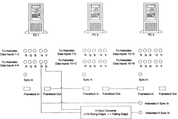
The new platform to drive Holovideo consists of three PCs, each with a single nVidia Quadro FX 3000G. Each Quadro FX 3000G is configured in dual-head mode and therefore outputs two sets of red, green, and blue, for a total of six output channels from each card. The six outputs from each of the three cards are synchronized using the Quadro FX 3000G's frame lock feature. The 18 outputs are sent directly to Holovideo's 18 parallel data inputs. Holovideo's vertical sync input is driven directly by the vertical sync signal from one of the video cards. The horizontal sync output from one of the cards is converted from the PC video mode to Holovideo's video mode by a dedicated TTL circuit. The output of the converter circuit is used to drive Holovideo's horizontal
HU ~--U
HU]M-r_1 0000 ru 000 1 OODO O O O
PC 1 PC 2 PC3
To Holovideo 000 00 To Hokvideo 000 00 To Holodeo 000 00
Datalnputs 1-3 R G B H V Datalnputs 7-9 R G B H V Datalnputs 13-15 R G B H V
To Hoovideo T000oieoOO 0 0To Datalnpu Holovideo 1012 000 00 Datatnputsl618To Holavideo, 000 00
Data Inputs 4-6 R G B D R G B H V R G B H V
0 0 0
Sync In Sync in Syncin
Framelock In Framelock Out Framelock In Framelock Out Frarnelock In Framelock Out
0 Holovideo V Sync In H Sync Converter
(176 Rising Edges -> 1 Failing Edge) Holovtdeo H Sync In
Figure 10: Architecture overview of the new system.
5.3 Data inputs
5.3.1 Requirements from Holovideo
To supply the data inputs, the new system must be capable of outputting 18 synchronized channels. Each channel must be capable of outputting 8 sequential blocks of 256K samples (for a total of 2,097,152 data samples) followed by 2 sequential blocks of 256K zero-valued samples. Blocks must be spaced by the 0.9ms horizontal blanking time of the display. The sequence of 10 blocks of 256K samples must be repeated at 30Hz.
5.3.2 Choice of video card
that synchronize their output to a common source. The technology that allows a video card to accept a timing input and therefore to synchronize its output with an external timing source is called genlock.
Although many modem video chips have the ability to synchronize to an external source (including those from ATI, nVidia, and 3Dlabs), it is a rarely used feature on PCs and is therefore not exposed by most video card manufacturers. At the time of this writing, there are only two mass produced commercially available chips that support the genlock feature: the nVidia Quadro FX 3000G and the 3Dlabs Wildcat II 51 10-G. For driver quality, hardware performance, and future upgradability, we chose to use the Quadro FX 3000G. PNY is currently the only board manufacturer that makes a video card based on the Quadro FX 3000G.
5.3.3 nVidia Quadro FX 3000G output specifications
The Quadro FX 3000G has support for driving two displays. Each output is equipped with a 400MHz DAC [11]. The two outputs are driven by the same chip with the same timing source; therefore, the two sets of RGB outputs on a single card are synchronized.
5.3.3.1 Synchronizing outputs
There are two features that enable multiple Quadro FX 3000Gs to synchronize their output signals: genlock (also known as frame sync) and frame lock. [12]
The video card accepts a BNC genlock input to which it can match its video mode timing with several configurable parameters. The genlock input can accept a NTSC/PAL, HDTV, or TTL format timing source. The drivers support synchronizing to the genlock input with a configurable input polarity and phase delay from the timing trigger. They also support sampling the input timing source by ignoring a configurable integer number of input triggers.
5.3.3.1.2 Frame lock
Frame lock allows the video card to synchronize output frames across multiple Quadro FX 3000Gs. The frame lock input allows a group of video cards to synchronize both frame redraws (synchronize vertical sync pulses) and frame buffer swaps (synchronize changes to the output data). The video card accepts a RJ45 frame lock input and provides a RJ45 frame lock output. In this way, video cards can be connected with a linear chain of Ethernet cables to synchronize their output channels.
5.3.3.2 Video mode limitations 5.3.3.2.1 Video mode background
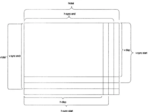
A video mode is described by 9 parameters: the dot clock speed, four for the horizontal timing and four for the vertical timing. These parameters characterize the number and shape of the displayed pixels, the size of the horizontal and vertical blanking, and the size of the horizontal and vertical sync pulses. The dot clock speed is the rate at which pixels
data. The second value, hsyncstart, is the number of pixels into the horizontal line at which the horizontal sync pulse beings. The third value, hsyncend, is the number of pixels into the horizontal line at which the horizontal sync pulse ends. The fourth value,
htotal, is the total number of pixels in a horizontal line. The difference between hsyncend and hsyncstart is the width of the horizontal sync pulse. The value of htotal less the
width of the sync pulse and hdisp is the amount of horizontal blanking.
The four values for the vertical timing specify how horizontal lines stack together to fill a single frame. The first value, vdisp, is the number of horizontal lines that contain display data. The second value, vsyncstart, is the number of lines into the frame at which the vertical sync pulse beings. The third value, vsyncend, is the number of pixels into the vertical frame at which the vertical sync pulse ends. The fourth value, vtotal, is the total number of horizontal lines in a complete frame. The difference between vsyncend and
vsyncstart is the width of the vertical sync pulse. The value of vtotal less the width of the
htcti hsend v synic start V tctal V S~ffE h dsp h synr start
Figure 11: Video mode parameters. 5.3.3.2.2 Limitations
The drivers for the Quadro FX 3000G, as well as for most video cards, have restrictions on the values for video mode parameters. All horizontal timing values must be multiples of 8. Also, htotal must be greater than hsyncend, which must be greater than hsyncstart. This means that the minimum horizontal blanking and the minimum horizontal sync pulse width are both 8 pixels. The vertical timing parameters are not restricted to multiples of 8 but do have analogous requirements that vtotal be greater than vsyncend, which is greater than vsyncstart. Additionally, the maximum vertical sync pulse width is
16 lines. The maximum value for hdisp is 4,096 and the maximum value for vdisp is 2400.
5.3.4 Constructing 18 synchronized data outputs
The Quadro FX 3000G can provide a maximum of 6 parallel data outputs by using each red, green, and blue channel in a dual-head configuration as a separate data output. We therefore need a minimum of 3 video cards to provide the necessary 18 outputs. Since we will also use the video cards to compute holograms, there are advantages to using more video cards with each card outputting fewer channels. For example, we could use a single-head configuration for 6 video cards, only the red channel with a dual-head configuration for 9 video cards, or only the red channel with a single-head configuration for 18 cards. For monetary reasons and to prove that we can drive Holovideo with as few PCs as possible, we chose to use only 3 video cards. The 3 video cards are connected together in a linear chain using the video cards' frame lock feature. Since we only need to synchronize the cards among each other and not to an external source, the genlock feature of the cards is not used.
5.3.5 Video mode
Holovideo has a horizontal data line length of 256K pixels plus a 0.9 ms horizontal blanking period. For a 2.4 ms active period, this gives a total of 360,448 samples per horizontal line. For each of the 18 channels, there are 8 vertically stacked lines, followed by a vertical sync pulse period and a vertical blanking period whose combined times are equal to the length of two lines, for a total of 10 vertical lines.
The video card limits the maximum horizontal line display size to 4,096 pixels. We therefore cannot output one line of Holovideo input as a single line of PC output. Our
method, however, we cannot rely on the video card's horizontal blanking to provide for Holovideo's horizontal blanking. To get around this, we expand our video mode's display pixels to include pixels for Holovideo's horizontal blanking time and write zero
values to those pixels.
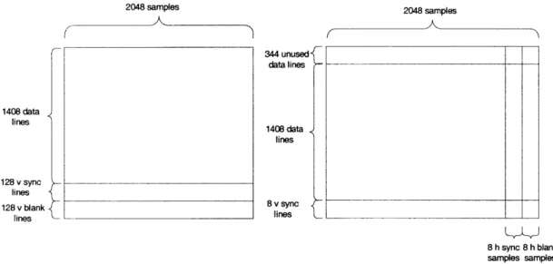
Our target number of display samples per Holovideo line is 360,448. For various reasons, we would like the video card horizontal line length to be a multiple of 1K. To achieve the desired number of samples, we can either use 176 vertical lines with a 2,048 sample line length or 88 vertical lines with a 4,096 sample line length. As we'll show later, changing the number of vertical lines is more difficult than changing the horizontal line length. Since 4,096 is the maximum line length the drivers will accept, to allow for future increases in the number of samples in a hololine, we chose to use 176 vertical lines at 2,048 samples per line. This configuration gives 128 vertical lines worth of fringe pattern data and 48 lines worth of horizontal blanking values.
Each horizontal line on the video card also includes pixels for the horizontal sync period and the horizontal blanking period. Since the video card restricts both the horizontal sync period and the horizontal blanking period to be a minimum of 8 pixels each, we must subtract the 16 unused pixels from each horizontal line's display size. We arrive at values of hdisp=2032, hsyncstart=2032, hsyncend=2040, and htotal=2048. This means that 16 out of every 2,048 pixels fed to Holovideo will be blank, amounting to a loss of
Each line of Holovideo input requires 176 horizontal lines of PC output. Each channel drives 8 lines of Holovideo input so we need a total of 1,408 lines of output data on the video card. We need a vertical sync period and vertical blanking period that sum to 2 lines of Holovideo input or 352 lines of video card output. We use the minimum value of 8 lines for the vertical sync period. Ideally, we would use 344 lines of vertical blanking to fill the remaining blanking time required by Holovideo. However, when frame lock is enabled on the Quadro FX 3000G, the video drivers reconfigure the video mode and remove the vertical blanking period. To get around this, we use the minimum value of 8 pixels for the vertical blanking period and instead add an additional 344 lines of data pixels. To match what Holovideo is expecting, we add the additional lines at the beginning of the display pixels and zero fill them. The video mode values are then
vdisp=1744, vsyncstart=1752, vsyncend=1760, and vtotal=1768. When the drivers
remove the vertical blanking period of 8 lines, the total number of lines is 1,760 as expected by Holovideo.
The value for the dot clock rate is chosen to make the vertical refresh rate 30Hz. When the drivers alter the video mode and remove the vertical blanking period, they also rescale the dot clock value to maintain the same vertical refresh rate. We therefore choose a value to achieve 30Hz with htotal=2048 and vtotal=1768. For an XFree86 modeline style input, the dot clock value is 108.626.
2048 samples 2048 samples 344 unused data lines 1408 data lines 1408 data lines 128 v sync lines 128 v blank 8 v sync lines lines 8 h sync 8 h blank samples samples
Figure 12: Video mode diagrams for a single output channel. The first image is the ideal PC video mode. The second image is the video mode we actually use after the drivers remove the vertical blanking.
The complete XFree86 modeline is:
ModeLine "2048x1760" 108.626 2032 2032 2040 2048 1752 1752 1760 1768 +hsync +vsync
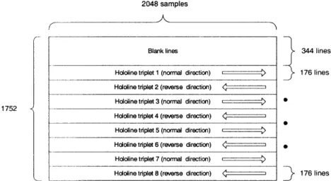
5.3.5.1 Hologram framebuffer data format
As per the discussion above, the framebuffer for each channel is 2,032 samples wide and 1,752 lines tall. To write a fringe pattern to the framebuffer for display, the first 344 lines must be black. The next 176 lines contain the first three hololines output by the framebuffer (the first line in the red channel, the second in green, and the third in blue). The following 176 lines contain the second three hololines, and so on for a total of 8 hololine triplets.
2048 samples
Blank lines 344 lines
Hololine triplet 1 (normal direction) 176 lines
Hololine triplet 2 (reverse direction) < 1 Hololine triplet 3 (normal direction) E ) S
1752
Hololine triplet 4 (reverse direction)
Hololine triplet 5 (normal direction) ) Hololine triplet 6 (reverse direction) *
Hololine triplet 7 (normal direction) r )
Hololine triplet 8 (reverse direction) < z 176 lines
Figure 13: The format for writing a holographic fringe pattern to the framebuffer.
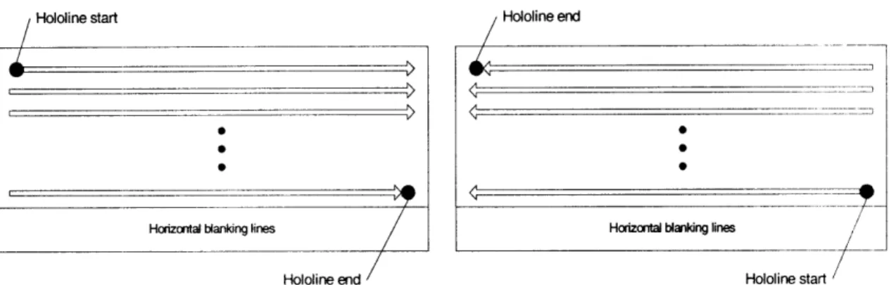
Each channel of each 176-line tall hololine triplet outputs a single long holographic fringe pattern. The first 128 lines contain fringe pattern data and the last 48 lines are zero filled. To accommodate the display's boustrophedonic scanning pattern, alternating triplets are stored in normal and reverse order. For a normal direction triplet, the first sample of the fringe pattern is stored at the first location and the last sample at the last location. Fringe pattern samples are laid down left to right and broken up over the 176 vertical lines from top to bottom. For a reverse direction triplet, the first sample of the fringe pattern is stored at the last location and the last sample at the first location. Fringe pattern samples are laid down right to left and broken up over the 176 vertical lines from bottom to top.
Hololine start Hololine end
Horizontal blanking lines Horizontal blanking lines
Hololine end Hololine start
Figure 14: The format of each hololine in the framebuffer. The first image is the format for a normal direction hololine. The second image is the format for a reverse direction hololine.
Because of our inability to remove the horizontal blanking, the framebuffer is 16 samples narrower than it should be, resulting in a loss of 2,048 samples per hololine. To write a fringe pattern to the framebuffer, we assume the framebuffer is the correct 2,048 samples wide and drop the 16 samples per horizontal line that are not available for writing. In contrast to dropping the last 2K samples, our method has several benefits. First, it preserves our ability to fit exactly two 1,024-sample hogels on each horizontal line. Second, if the missing samples were to produce visible artifacts, the image would appear to have a black grating in front of it as opposed to appearing as if the image were cut into vertical slices and horizontally separated (we do not introduce horizontal stretching and discontinuities). Third, dropping the last 2K samples would have a noticeable impact on the width of the view zone.
5.4 Horizontal sync input
5.4.2 Driving the horizontal sync input
The horizontal sync output of the video cards is not suitable to drive Holovideo directly. The video card horizontal sync pulses once per video card line, or 176 times per Holovideo line. To convert the video card horizontal sync signal to a signal suitable to drive Holovideo, we built a simple TTL circuit that outputs one rising edge for every 176 rising edges on the input signal. The horizontal sync signal from a video card is used as the input to the converter circuit and its output is sent directly to Holovideo's horizontal sync input. Refer to Appendix A for a schematic of the horizontal sync converter circuit.
5.5 Vertical sync input
5.5.1 Requirements from Holovideo
To supply the vertical sync signal, the system must output a TTL rising edge at the beginning of the Holovideo line and the output must return to low before the end of that
line.
5.5.2 Driving the vertical sync input
The vertical sync signal from any of the video cards is suitable to directly drive Holovideo's vertical sync input.