HAL Id: cea-01576460
https://hal-cea.archives-ouvertes.fr/cea-01576460
Submitted on 31 Aug 2017HAL is a multi-disciplinary open access
archive for the deposit and dissemination of sci-entific research documents, whether they are pub-lished or not. The documents may come from teaching and research institutions in France or abroad, or from public or private research centers.
L’archive ouverte pluridisciplinaire HAL, est destinée au dépôt et à la diffusion de documents scientifiques de niveau recherche, publiés ou non, émanant des établissements d’enseignement et de recherche français ou étrangers, des laboratoires publics ou privés.
Design and first applications of the ITER integrated
modelling & analysis suite
Frédéric Imbeaux, Simon Pinches, Jonathan Lister, Y. Buravand, Thomas
Casper, Basil Duval, B. Guillerminet, Masanari Hosokawa, Wayne Houlberg,
Philippe Huynh, et al.
To cite this version:
Frédéric Imbeaux, Simon Pinches, Jonathan Lister, Y. Buravand, Thomas Casper, et al.. Design and first applications of the ITER integrated modelling & analysis suite. Nuclear Fusion, IOP Publishing, 2015, 55, pp.123006. �10.1088/0029-5515/55/12/123006�. �cea-01576460�
1. Introduction
The ITER Integrated Modelling & Analysis Suite (IMAS) will support both plasma operation and research activities on the ITER tokamak experiment. The IMAS will be accessible to all ITER Members as a key tool for the scientific exploitation of ITER. It will allow collective development of integrated modelling tools, by sharing data, code components and, ulti-mately, workflows based on coupling together various code components. Its design started in 2011 and a first prototype of the IMAS infrastructure has already been implemented at the ITER organization (IO). The purpose of this paper is to describe the essential features of the IMAS design, the imple-mented prototype infrastructure (section 2), as well as the first physics applications that have been developed under the
IMAS infrastructure (section 3). The key target application is a plasma simulator coupled to a simulator of the plasma control system, which are implemented under a co-simulation scheme presented in section 4.
2. IMAS infrastructure
2.1. Overview
The IMAS infrastructure is a modular set of components enabling collective development and execution of integrated modelling applications. Every component carries out a dedi-cated functionality and the modularity is a critical element to facilitate the maintenance of the IMAS infrastructure over its 30 years lifespan. Indeed, changes will inevitably occur in
Nuclear Fusion
Design and first applications of the ITER
integrated modelling
& analysis suite
F. Imbeaux1, S.D. Pinches2, J.B. Lister3, Y. Buravand1, T. Casper2, B. Duval3,
B.Guillerminet1, M. Hosokawa2, W. Houlberg2, P. Huynh1, S.H. Kim2,
G. Manduchi4, M.Owsiak5, B. Palak5, M. Plociennik5, G. Rouault6,
O. Sauter3 and P. Strand7
1 CEA, IRFM, F-13108 Saint-Paul-lez-Durance, France
2 ITER Organization, Route de Vinon-sur-Verdon, CS 90 046, 13067 St. Paul Lez Durance Cedex, France 3 Ecole Polytechnique Fédérale de Lausanne (EPFL), Centre de Recherches en Physique des Plasmas,
Association EURATOM-Confédération Suisse, CH-1015 Lausanne, Switzerland
4 Consorzio RFX, Corso Stati Uniti 4, 35127 Padova, Italy
5 PSNC, Poznan Supercomputing and Networking Center, Poznan, Poland 6 CORYS T.E.S.S., 44 rue des Berges, 38024 Grenoble cedex 1, France 7 Chalmers University of Technology, S-41296 Göteborg, Sweden
E-mail: [email protected]
Received 19 December 2014, revised 22 September 2015 Accepted for publication 13 October 2015
Published 30 October 2015
Abstract
The ITER Integrated Modelling & Analysis Suite (IMAS) will support both plasma operation and research activities on the ITER tokamak experiment. The IMAS will be accessible to all ITER members as a key tool for the scientific exploitation of ITER. The backbone of the IMAS infrastructure is a standardized, machine-generic data model that represents simulated and experimental data with identical structures. The other outcomes of the IMAS design and prototyping phase are a set of tools to access data and design integrated modelling workflows, as well as first plasma simulators workflows and components implemented with various degrees of modularity.
Keywords: integrated modelling, modelling infrastructure, ITER, plasma control system (Some figures may appear in colour only in the online journal)
F. Imbeaux et al Printed in the UK 123006 NUFUAU © 2015 IAEA, Vienna 2015 55 Nucl. Fusion NF 0029-5515 10.1088/0029-5515/55/12/123006
Papers
12 Nuclear Fusion IOPInternational Atomic Energy Agency
doi:10.1088/0029-5515/55/12/123006
software and hardware technologies, as well in the methods used to solve physics problems and one must be able to replace a component with minimal impact on the others.
The backbone of the IMAS infrastructure is a standard-ized data model, called the ITER Physics Data Model (PDM). This is not only important for coupling physics components together (solving the N2 interfaces problem), but also to make
sure that every input and output of the physics components is saved in a standard way. It removes the ‘private file’ problem, i.e. when codes access data from a private format or location which is unknown to the infrastructure, and the ‘private defini-tion’ problem, i.e. when the data accessed by the code has no (or not clearly enough) documented definition.
To access data, a data model aware Application Programming Interface (API) has been developed for various programming languages. It enables cross-language commu-nication and a way to store and retrieve data from a remotely accessible storage that becomes a prototype of an ITER physics database.
Physics components, once interfaced to the data model, can be coupled into an Integrated Modelling workflow orchestrated by a workflow engine. A workflow component generator is provided to automate the integration of a physics component in the workflow engine. With these tools, a physics code developer can seamlessly wrap his/her component with data access methods and even develop IM workflows.
This global design of the IMAS infrastructure has been largely inspired by the developments of the European Integrated Modelling Task Force (EU-ITM) [1–3], a pro-ject which also puts a strong emphasis on the development of integrated modelling standards for a large community of researchers. A large part of the IMAS infrastructure software reuses EU-ITM developments, although the original source code sometimes required significant adaptations to be con-sistent with the ITER Physics Data Model, which has sig-nificant improvements and new features with respect to the EU-ITM data model [3] (see section 2.2). Although other integrated modelling frameworks have been developed in the previous decade in the international fusion community, they did not attach enough importance to the development of a standard language for the scientific community for describing a fusion experiment and the associated physics, a goal of utmost importance in our view owing to the international char-acter of ITER. In contrast, the OMFIT framework [4] takes the opposite approach and facilitates using together codes without following any common standard by providing a GUI environment to set input data and schedule execution. Data remains expressed in code-specific form, code coupling has to be developed for every pair of codes, and the experiment-generic character of the physics components is not enforced.
It has to be emphasized that the IMAS infrastructure remains fully modular, in the sense that the usage of the Physics Data Model does not constrain the choice of work-flow engine for executing codes. Even a stand-alone pro-gram can be considered IMAS-compliant as long as it uses exclusively the PDM for expressing its input/output data. A graphical workflow engine (Kepler [5]) has been inte-grated to the IMAS prototype because it allows exposing to
developers in an intuitive way the architecture of the work-flow (the way component are coupled but also convergence algorithms which are described explicitly in the fine grained modularization described in section 3.2), thus facilitating the collective development of IM workflows by the community. Moreover the interactive features of Kepler (such as pause / modify of a parameter / resume the simulation) were requested for the development of the Plasma Control System algorithms (see section 4). However, more user-oriented tools (e.g. a graphical interface for editing input data, parameterizing a workflow and schedule execution such as OMFIT) can also become part of the IMAS infrastructure, for different reasons and purposes than the workflow engine, under the condition that these tools are compliant with the Physics Data Model. Other interesting features such as the CPU advanced reserva-tion mechanism and load balancing of workflow components implemented in IPS [6] to optimize the execution of work-flows on a single high performance computer could also be of interest for some IMAS applications, and could be added to the IMAS infrastructure either directly by integrating a PDM-enabled IPS as an alternative workflow engine, or by imple-menting them around Kepler (a prototype of such a Kepler implementation has been developed).
Finally version control and regression testing systems are essential for collective development of the IMAS infrastruc-ture and of its physics suite.
These key elements of the IMAS infrastructure have been already implemented in a prototype form and are described in more detail in the sections below.
2.2. The ITER physics data model
The data model provides information for data providers and data consumers on what data exist, what they are called and how they are structured as seen by the user. It is important to stress that the ITER physics data model corresponds to the user’s view of the data and is a priori independent of how the data is stored in the back-end. This data model potentially encompasses all data of physics interest, i.e. its applications are not restricted to IMAS codes but are foreseen to cover most of the scientific activities related to the ITER experi-ment. The ITER physics data model aims at being the main gate to data for scientific exploitation, both for code inter-facing and hands-on data browsing by experimentalists after a pulse. Another important goal is to make the data model device-generic, i.e. it is a magnetic fusion oriented data model usable for any fusion device.
The data model consists thus of two parts: a ‘data dictionary’ part which is the one seen by the user and is device-generic; a ‘data model’ part which is a list of expressions making the link between the nodes of the generic data dictionary and the methods for accessing data for a particular experiment and a particular pulse number. This design allows the user to see a unique representation (the data dictionary) for any fusion device and thus to apply the IMAS transparently to any experi-ment, ITER being only a particular case of application.
To ease the comparison between simulation and experi-ments, the data dictionary is unique for simulated and
experimental data, i.e. the same data structures are used to represent data measured during an experiment (e.g. the elec-tron temperature from a Thomson scattering diagnostic) and its simulated counterpart.
The ITER physics data model is physics oriented: therefore it must be able to evolve as the representation of the physics phenomena developed by the scientific community evolves. A precise lifecycle procedure has been defined to allow the data model to evolve and be jointly developed by multiple teams. In addition, precise design rules for the data dictionary have been defined to maintain its global homogeneity.
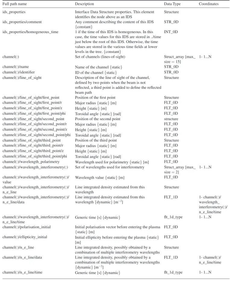
An Interface Data Structure (IDS) is an entry point of the data dictionary that can be used as a single entity to be used by a user; examples are the full description of a tokamak sub-system (diagnostic, heating sub-system, …) or an abstract physical concept (equilibrium, set of core plasma profiles, wave propa-gation, …); this concept allows tracing of data provenance and allows simple transfer of large numbers of variables between loosely or tightly coupled applications; the IDS thereby define standardized interface points between IMAS physics compo-nents. An IDS is a part of the data dictionary, like an entry point into it, thus the IMAS components are interfaced with the same structures as those constituting the data dictionary. An IDS is marked by having a child ids_properties node, containing traceability and self-description information. An IDS may contain both time-dependent and time-independent data, thus grouping for example diagnostic measurements and the description of the diagnostic setup (geometry, calibration data, …). One important idea here is to make the machine description fully explicit in the data model in order to make them accessible by all users of an experiment (while in present experiments these data are often scattered in different loca-tions and formats and are difficult to access). Within an IDS, data may have different time bases to reflect the fact that in an experiment, data may be acquired at different rates. Again, the philosophy is to have a full description of the whole tokamak and its associated physics in an experiment-generic and code-generic form, making all physical data explicit, traceable and accessible to the user. Details of the existing IDS structures can be found at https://imas.iter.org/. An example is provided in table 1 for the description of the interfero-polarimeter diagnostic.
The design of the ITER physics model has benefited from the European integrated modelling task force (EU-ITM) expe-rience with the so-called Consistent Physical Objects (CPOs) [3]. The idea of a structured, device-generic data dictionary providing a list of standardized interfaces between IM compo-nents as well as the granularity of these interfaces stems from this experience. Nonetheless, some new key aspects have been introduced in the design, in particular the dual notion of data dictionary and data model, the capability of handling multiple asynchronous time bases in a single IDS (this flex-ibility is needed to represent experimental quantities as they are acquired and to not lose information) and the naming and structuring conventions of the data dictionary. The resulting ITER physics data model is therefore new and original, ben-efitting from lessons learned from previous experience with similar goals.
The present status of the data dictionary is as follows: about 30 IDS have been designed and start being used by the first IMAS applications, essentially covering the needs of core transport solvers with free boundary equilibrium. Examples of diagnostic subsystems have also been designed. The data dic-tionary will continue its expansion in the near future as new physics applications are added to the IMAS. The concept of ‘data model’, i.e. a formal link between the data dictionary and the access method, has been demonstrated under a sepa-rate Matlab prototype for a few JET and TCV examples but is not implemented yet under the default access layer.
2.3. The access layer
A prototype access layer, based on the Universal Access Layer developed by the EU-ITM [7] has been implemented to allow data access for the first IMAS applications. It has been made compliant with the ITER Physics data dictionary and has APIs for Fortran, C + +, Python, Java and Matlab. It primarily writes data files on disk and features also a memory cache mechanism for fast data transfer between workflow components. Remote data access is also available: a proce-dure has been created to enable access layer installation on a local computer, i.e. the user can choose to access data either locally on his computer or remotely on the ITER cluster. This prototype access layer operates only at the IDS level, allowing essential operations such as put or get data, time interpolation, access to single time slices of data.
In parallel to the implementation of this prototype, the design of the architecture and functionalities of the longer term access layer has been carried out. The final product should not be restricted to IMAS usage but should allow access to any ITER data. It should not only allow operations based on the ITER Physics data model but, for example, operations expressed in terms of the ITER CODAC data model will also be possible through the same interface. The design is based on a client-server architecture and features the data dictionary / data model correspondence described in the previous section. This is a joint development with the ITER CODAC which will start next year and eventually replace the present access layer prototype.
2.4. Workflow engine and component generator
Physics components, once interfaced to the data model, can be coupled into an Integrated Modelling workflow. Different methods may be used: components written in the same pro-gramming language can be straightforwardly coupled, e.g. as subroutines within a main program. Components written in different languages may use the access layer to exchange data and then be scheduled e.g. by a simple script. In case of complex workflows involving a large number of components, a workflow engine is provided within the IMAS infrastruc-ture to help the development. The workflow engine allows designing, debugging, and running IMAS workflows. It hides the complexity of code scheduling and data transfer between components. A useful feature is a graphical interface for visualising and editing the workflow and the data flows. The
Table 1. Documentation of the interfero_polarimeter IDS (automatically generated from the data dictionary, version 3.2.0). The first column provides the path of all nodes in the structure, the second column gives its description, as well as its units and whether data depends on time (‘dynamic’) or is constant or belong to machine description (‘static’). The third column provides the type of data. The fourth column provides the location of the data coordinates, when it is an array; the indication 1…N means that the node has no coordinate in the structure, usually because the node is itself a coordinate of other nodes.
Full path name Description Data Type Coordinates ids_properties Interface Data Structure properties. This element
identifies the node above as an IDS
Structure ids_properties/comment Any comment describing the content of this IDS
{constant} STR_0D ids_properties/homogeneous_time 1 if the time of this IDS is homogeneous. In this
case, the time values for this IDS are stored in ../time just below the root of this IDS. Otherwise, the time values are stored in the various time fields at lower levels in the tree. {constant}
INT_0D
channel(:) Set of channels (lines-of-sight) Struct_array [max_
size = 15] 1- 1...N channel(:)/name Name of the channel {static} STR_0D
channel(:)/identifier ID of the channel {static} STR_0D channel(:)/line_of_sight Description of the line of sight of the channel,
defined by two points when the beam is not
reflected, a third point is added to define the reflected beam path
Structure
channel(:)/line_of_sight/first_point Position of the first point Structure channel(:)/line_of_sight/first_point/r Major radius {static} [m] FLT_0D channel(:)/line_of_sight/first_point/z Height {static} [m] FLT_0D channel(:)/line_of_sight/first_point/phi Toroidal angle {static} [rad] FLT_0D channel(:)/line_of_sight/second_point Position of the second point structure channel(:)/line_of_sight/second_point/r Major radius {static} [m] FLT_0D channel(:)/line_of_sight/second_point/z Height {static} [m] FLT_0D channel(:)/line_of_sight/second_point/phi Toroidal angle {static} [rad] FLT_0D channel(:)/line_of_sight/third_point Position of the third point Structure channel(:)/line_of_sight/third_point/r Major radius {static} [m] FLT_0D channel(:)/line_of_sight/third_point/z Height {static} [m] FLT_0D channel(:)/line_of_sight/third_point/phi Toroidal angle {static} [rad] FLT_0D channel(:)/wavelength_polarimetry Wavelength used for polarimetry {static} [m] FLT_0D
channel(:)/wavelength_interferometry(:) Set of wavelengths used for interferometry Struct_array [max_ size = 2]
1- 1...N channel(:)/wavelength_interferometry(:)/
value Wavelength value {static} [m]
FLT_0D channel(:)/wavelength_interferometry(:)/
n_e_line
Line integrated density estimated from this wavelength
Structure channel(:)/wavelength_interferometry(:)/
n_e_line/data
Line integrated density estimated from this
wavelength {dynamic} [m−2] FLT_1D 1- channel(:)/wavelength_
interferometry(:)/ n_e_line/time channel(:)/wavelength_interferometry(:)/
n_e_line/time Generic time [s] {dynamic}
flt_1d_type 1- 1...N channel(:)/polarisation_initial Initial polarisation vector before entering the plasma
{static} [m]
FLT_0D channel(:)/ellipticity_initial Initial ellipticity before entering the plasma {static}
[m]
FLT_0D channel(:)/n_e_line Line integrated density, possibly obtained by a
combination of multiple interferometry wavelengths
Structure channel(:)/n_e_line/data Line integrated density, possibly obtained by a
combination of multiple interferometry wavelengths {dynamic} [m−2]
FLT_1D 1- channel(:)/ n_e_line/time channel(:)/n_e_line/time Generic time [s] {dynamic} flt_1d_type 1- 1...N
workflow engine should not be considered only as a scheduler, but as a way to expose complex and large workflows in a stan-dard way to a team of developers. This is thought to facilitate collective development and to be an advantage with respect to developing such workflows within a classical program. In the latter case, the structure of the program may be less obvious and inserting a new component may be more subject to code-specific peculiarities. In this context, the workflow engine is primarily a tool for developers or advanced users, while the broad range of users would rather benefit from simpler GUIs to drive the exploitation of production workflows. In 2011 the available open source workflow engines have been evaluated and Kepler [5] has been selected for the development of the first IMAS workflows.
Another key aspect of the workflow development chain is the automated generation of workflow physics compo-nents from the physics modules. The primary function for the ‘component generator’ tool is to seamlessly turn an original physics code with data dictionary compliant interfaces into a component of a workflow engine. The integration to the work-flow engine becomes fully automated and the data exchange between components becomes also seamlessly managed in a standard way by access layer calls wrapped around the physics code (see figure 1). The workflow engine and data exchange
software of the IMAS may thus be modified without impacting the physics code developers: only the component generator will need to be updated. Since the integration of a component is automated, it can be done in a single step for multiple con-texts, i.e. to generate simultaneously a stand-alone program and components for multiple workflow engines. Presently, the IMAS component generator produces (i) a stand-alone pro-gram, (ii) a Kepler actor (with various execution modes: same process as Kepler, batch job submission, possibly using MPI, execution within a debugger) and (iii) a component callable by Python scripts.
2.5. Distributed version control and local deployment
All IMAS software (both infrastructure and physics compo-nents) are under version control using GIT [8], a distributed version control system. Its distributed feature is a key one in the context of the distribution of IMAS within the ITER members institutes. Indeed local installations of IMAS are foreseen, (i) to ease local development of new IMAS soft-ware and usage in the frame of ITER exploitation and also (ii) to enable the usage of IMAS for local experiments. Using GIT, local IMAS repositories can be used for development and, when agreed, shared with the official IMAS repositories
channel(:)/faraday_angle Faraday angle (variation of the Faraday angle induced by crossing the plasma)
Structure channel(:)/faraday_angle/data Faraday angle (variation of the Faraday angle
induced by crossing the plasma) {dynamic} [rad]
FLT_1D 1- channel(:)/ faraday_angle/ time
channel(:)/faraday_angle/time Generic time [s] {dynamic} flt_1d_type 1- 1...N channel(:)/ellipticity Ellipticity structure
channel(:)/ellipticity/data Ellipticity {dynamic} [-] FLT_1D 1- channel(:)/ ellipticity/time channel(:)/ellipticity/time Generic time [s] {dynamic} flt_1d_type 1- 1...N channel(:)/validity_timed Indicator of the validity of the channel as a function
of time (0 means valid, negative values mean non-valid)
Structure channel(:)/validity_timed/data Indicator of the validity of the channel as a function
of time (0 means valid, negative values mean non-valid) {dynamic}
INT_1D 1- channel(:)/ validity_timed/ time
channel(:)/validity_timed/time Generic time [s] {dynamic} flt_1d_type 1- 1...N channel(:)/validity Indicator of the validity of the channel for the whole
acquisition period (0 means valid, negative values mean non-valid) {static}
INT_0D code Generic decription of the code specific parameters
for the code that has produced this IDS
Structure code/name Name of the code {constant} STR_0D code/version Version of the code {constant} STR_0D code/parameters List of the code specific parameters in XML format
{constant}
STR_0D code/output_flag Output flag: 0 means the run is successful, other
values mean some difficulty has been encountered, the exact meaning is then code specific. Negative values mean the result shall not be used. {dynamic}
INT_1D 1- time
time Generic time [s] {dynamic} flt_1d_type 1- 1...N
Table 1. (Continued)
at ITER. Branch management procedures are being drafted to guide development, which is expected to be collective and world-wide.
To enable this vision of a collective IMAS development, a local installation procedure of IMAS is being developed. Every IMAS component will be revision controlled using GIT. The motivation for this is to have a guaranteed trace-ability of versions of the IMAS components in use at different sites.
Regression testing is also being implemented on every IMAS component (physics or infrastructure).
3. IMAS first physics applications
First applications have been integrated under the prototype IMAS infrastructure to demonstrate its expected function-alities. The initial application for prototyping the IMAS infrastructure and developing the tools required for pulse preparation is a plasma simulator, i.e. a transport solver with free boundary equilibrium capability (and later including also scrape-off-layer and plasma-wall interaction modelling). This plasma simulator, used in conjunction with the plasma con-trol system simulation platform (PCSSP) [9–11], forms a full tokamak simulator allowing developing control strategies. This tool is planned to be used systematically as part of the pulse validation procedure, a requisite prior to the execution of any pulse on the real ITER experiment.
Different strategies can be used to implement the plasma simulator. The simplest approach is to use existing plasma simulators as they are and integrate them as a single, mono-lithic component of a workflow. Examples of this most direct approach, although not satisfying from the point of view
of modularity, are described in section 3.1. A finer grained integration is desirable and examples of elementary physics components integrated to IMAS are presented in section 3.2. Different choices can also be made regarding the implementa-tion of the plasma control system (PCS) simulaimplementa-tion. In the first Figure 1. The standard layered structure used in IMAS to enable the execution of the original physics solver and the data exchange with other components. The original, unmodified solver is shown as the innermost box (dark green). Around it, the data mapping layer (light blue) makes the mapping between the original solver data model and the ITER physics data model, resulting in a layer with standard interfaces (using IDSs). One level above, the next layer wraps the previous one with access layer calls (this is the layer generated automatically by the component generator). The outermost structure (light green) represents the launcher, which contains the knowledge of the workflow and the data flow and schedules the execution of the components. This structure is used systematically to organize the execution of components in layers of different functionalities. The only exception is for codes handling massive amounts of data, for which data access is usually parallelised and must be done inside the physics solver (no processor has enough memory to gather all data).
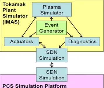
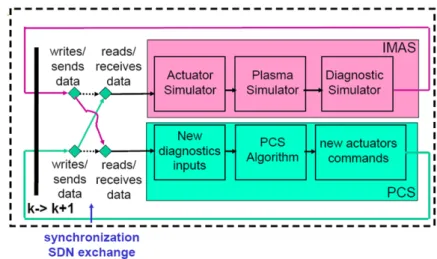
Figure 2. The structure of the full tokamak simulator. The SDN is the hardware used by the real PCS to communicate with the plant (receiving diagnostic information and sending actuator commands). In the simulation, it is simply an interface between the PCSSP and the tokamak plant simulator. The latter, residing in IMAS, simulates the plasma response, the actuators and the diagnostics. An event generator is added to test the behavior of the system in case of physical or technical ‘events’, e.g. L-H transition, appearance on a Neoclassical Tearing Mode, power supply interruption, diagnostic failure.
plasma simulator implementations described in section 3.1, the PCS simulation has been for simplicity implemented directly in Kepler or even kept within the original plasma component, while the PCSSP is normally an independent simulation plat-form (handled under Simulink®). To achieve this desired sep-aration of concerns between plasma physics on one hand and control aspects on the other hand, co-simulation techniques have been developed between Kepler and Simulink and are described in section 4.
3.1. Coarse-grained component integration
Plasma simulators are usually complex codes involving a large number of modules organised around a main solver of the 1D transport equations. Although they may have a modular internal structure, it is not necessarily easy to extract a given module and use it in a different context, because there can be significant internal dependencies. Therefore the simplest way (although not the most desirable one) of integrating an existing plasma simulator to a multi-purpose workflow engine is to do it as a single, monolithic component. This has been done with CORSICA [12, 13], which has been integrated as a single Kepler actor in a simple time loop workflow. Kepler controls the main time loop and calls CORSICA to solve the transport equations with free boundary equilibrium between two steps of the time loop. This is one of the most basic stages of workflow integration, where a time loop is created around a component working on a single time step (here the CORSICA solver executed from time t to t + dt).
In general, the advantage of using a workflow is to make it easy to couple different physics, engineering and control
components using standardized interfaces and schemes. Here the workflow allows coupling to CORSICA external compo-nents that may modify the dynamics of the simulation (e.g. an external plasma control simulator altering the actuator values, as demonstrated with the CORSICA workflow shown in figure 4, or an external MHD model altering the plasma profiles). These coupled models are developed independently of CORSICA, without requiring the knowledge of the code internals, and can be reused with any other transport solver in IMAS. The workflow thus provides an extended modelling capability with respect to the stand-alone CORSICA, which can be straightforwardly reused in multiple contexts.
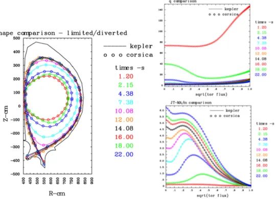
First, a technical verification of the CORSICA integration has been made by comparing the output of the Kepler workflow to a stand-alone CORSICA simulation (figure 3). In a second stage, to increase the modularity of the workflow, the vertical position control algorithm was moved outside CORSICA and implemented directly in Kepler as a new component of the workflow. It sends commands for the poloidal field systems simulated within the CORSICA component (figure 4). This workflow has been tested successfully and could control the plasma position during 10 s of an ITER hybrid scenario pla-teau; after 10 s the vertical control is voluntarily switched off in the simulation and a Vertical Displacement Event occurs as expected (figure 5).
A second, more modular, integration example has been made with the DINA transport and free boundary equilibrium solver [14]. In this application, the structure of the workflow (see figure 6) respects the modular logic of the full tokamak simulator presented in figure 2. The DINA plasma simulator is contained within the ‘Tokamak’ blue box and its execution is Figure 3. Verification of the CORSICA-IMAS coupling (‘kepler’, solid lines) against the stand-alone CORSICA (‘corsica’, circles): evolution of the plasma boundary (left) and the safety factor and current density profiles (right) during an ITER current ramp-up. Both frameworks provide exactly the same results and the curves are perfectly superimposed.
also commanded by a main time loop implemented explicitly in the Kepler workflow.
3.2. Fine-grained component integration
A finer granularity of the workflow description is nevertheless needed to be able to act on the components used within the plasma simulator itself. Making the internal structure of the plasma simulator explicit at the level of the workflow engine is a challenge but opens to a broader community the access to the components and even to the structure of the simulator itself (e.g. internal convergence or time loops). It makes the structure of the simulator fully transparent and enforces a standard method for coupling new components, independent
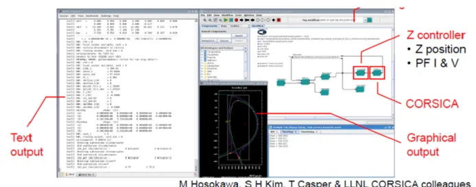
of a particular code or programming language. Prototypes of such fine grained transport solver workflows have been dem-onstrated already by the EU-ITM [1, 15] and it is foreseen to use a similar approach on IMAS. Fast data transfer between components, enabled by the memory cache mechanism of the access layer, as well as using a workflow engine written in a compiled language (Java for Kepler) are key elements to avoid a loss of performance with such fine grained workflows. It has been verified that the CRONOS-based European Transport Solver, fully modularized under Kepler has similar perfor-mances than the original CRONOS version [16] which was implemented under another framework, namely Matlab. Some components may require specific hardware (e.g. GPU) or use MPI and/or OpenMP for their parallelization. Solutions have Figure 4. Screenshot showing the interactive execution of CORSICA integrated as a single component in Kepler, with an external vertical position controller. The Kepler GUI can be seen at the top right of the screen, displaying graphically the structure of this simple time loop workflow.
Figure 5. VDE triggered at t = 310 s of an ITER hybrid scenario simulation with the CORSICA-IMAS workflow. Left: height of the magnetic axis. Middle: plasma shape and location of the gap measurements. Right: time traces of the gaps. The vertical dashed blue line indicates the time at which the vertical control is switched off.
been developed in the EU-ITM project to enable the usage of MPI and OpenMP for Kepler workflow components, together with various distributed computing strategies (remote submis-sion on grid or high performance computers, web services) [17, 18]. These solutions could be ported in the near future to the IMAS infrastructure to optimize the performance of various applications.
In preparation of the implementation of a fine grain trans-port solver, basic and essential components such as a prescribed boundary equilibrium code (CHEASE [19]) and a neoclassical component (NCLASS [20]) have been integrated to IMAS.
4. Co-simulation with the plasma control system simulation platform
In this section, we describe a technical development allowing co-simulation between the tokamak plant simulator (imple-mented under IMAS) and the plasma control system simulator (implemented under a separate platform, named the Plasma Control System simulation platform (PCSSP) [9–11]). The full tokamak simulator represented in figure 2 is thus imple-mented using two different workflow engines for IMAS and the PCSSP, respectively Kepler and Simulink® [21]. This required the development of this co-simulation technique.
4.1. Synchronization scheme
In ITER, the PCS runs the tokamak by exchanging informa-tion with the plant every specified Δtsync time-steps, typically
every 1 ms.
The dashed box represented in figure 7 repeats itself throughout the tokamak/simulation pulse and can be repre-sented as follows:
The schema represented in figure 8 is what is implemented in simulators. The write/read data exchange is performed only once per time-step, to reduce synchronisation burden. This implies that the PCS delivers new actuator demands at time
k + 2 based on information received at time k + 1. This delay is of course taken into account in the PCS model, to control the tokamak properly.
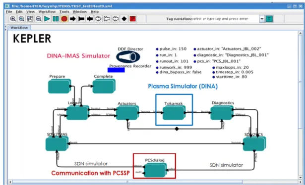
Figure 6. Overview of the implemented DINA-IMAS simulator (workflow designed and executed using the Kepler workflow engine), highlighting the coupling between the various elements of the full tokamak simulator: actuators, tokamak, diagnostics, plasma control system (PCS). The boxes correspond to high level components of the workflow and contain themselves more detailed sub-workflows. The arrows connecting the boxes represent the data flow, which consists of two main streams: the DINA simulation data bus (BUS), which stays on the IMAS side, and a representation of the ITER SDN, which is the interface between the PCS and the plant.
Figure 7. Schematic view of the tokamak-PCS coupling with synchronisation of information through the SDN every k predefined time-step. The PCS delivers actuators at k + 2 based on plasma parameters obtained at k + 1. A Δtsync difference which is taken
4.2. Global scheduling of the co-simulation
A co-simulation requires a master which will drive the whole calculation and schedule the execution of the worfklow engines according to the synchronization principles described above. Three options have been identified:
1. IMAS/Kepler is the driver and the PCSSP is called via a Kepler component
2. Simulink is the driver and the IMAS is called via an S-function
3. The two suites are executed from outside, typically from a script/light framework and are executing in parallel. One of the features of both Kepler and Simulink is to allow a graphical visualisation of the workflow and interactivity
during its execution: a user may visualise part of the data flow, pause the workflow, change a parameter and then continue the workflow execution. These features are quite useful for development of control algorithms, which can be fine-tuned by trial and error. Therefore the requirement was to maintain those interactive features of the workflow engines during the co-simulation. The three scheduling options described above have been tested and it has been found that, due to the par-ticularity of Simulink, full interactivity within Simulink was not guaranteed unless Simulink (that is the PCS environment) drove the coupled workflows. For this reason, it was decided to develop the co-simulation prototype using option 2.
The communication between the two workflow engine is implemented via TCP/IP sockets using the open source ZeroMQ software [22]. The content of the simulated Figure 8. IMAS/Tokamak-PCS coupling view as a time-loop incremental schema. This schema has been tested with a KEPLER-Simulink prototype.
Figure 9. Simulink part of the PCS-IMAS-Option 2 coupling. The box ‘simimasdialog’ contains an S-function within which the dialog with IMAS is provided.
‘synchronous data network’ (SDN) is exchanged via this technology at every synchronisation time step. Potentially, the usage of TCP/IP sockets allows executing the two simulators on different computers.
4.3. General structure of the workflows
The two workflows have a similar general structure: a time loop implementing a step by step evolution of duration Δtsync,
communication components to read/write the SDN messages from/to the other simulator, an application specific workflow for simulating either the plant (IMAS) or the PCS.
Figure 9 shows the top level of the Simulink workflow. It contains the PCS algorithm itself (‘PCS simulator’ box) and other elements to couple to the IMAS workflow engine, which is viewed from the Simulink side as an S-function (red ‘communi-cation with IMAS’ box). The ‘EventConf’ box provides a simple implementation of the event generator described on figure 2.
Clicking on the ‘start’ button in Simulink, in addition to initializing the Simulink workflow, also launches Kepler and starts the Kepler workflow execution. During the termination phase, Kepler is similarly closed from Simulink.
During normal execution, from time-step to time-step, the outputs of the PCS simulator are converted to the SDN Figure 10. IMAS part of the PCS-IMAS-Option 2 coupling. The box ‘PCSdialog’ contains an actor within which the dialog with PCS is provided. The conversion of the Kepler variables from/to the SDN structure is performed within the SDN2IMAS/SDN2PCS boxes.
Figure 11. Position of the magnetic axis, major radius (left) and height (right) during the DINA-PCSSP co-simulation of an ITER scenario. The vertical position controllers has a target of Z = 0.52 m (dashed line) and reacts to scenario events (this explains the transient observed at t = 0.39 s). 200 steps of Δtsync = 5 ms have been carried out in this first co-simulation with DINA.
structure (in our case an array of 150 values called ‘SDN simulator’ on the figure). A trigger event value, emulating an event configuration (see below), is added to the SDN array and these 151 values are made available to the IMAS dialog S-function. The simimasdialog function sends these data to IMAS via ZeroMQ and then awaits the IMAS output that con-sists of an array of the 150 values contained in the SDN struc-ture. Once received, they are converted back into PCS inputs. The controller then calculates the new actuators values and the loop may continue.
The plant simulator is included within Kepler as shown in figure 10. The ‘Actuators Simulator’, ‘Diagnostic Simulator’ and ‘Plasma Simulator’ boxes correspond to the boxes shown in figure 2. Since we are showing here the DINA-IMAS workflow implemented as a co-simulation, the workflow is almost identical to the one of figure 6, the difference being the ‘PCSdialog’ box which now contains the send/receive dialog with the PCS simulator. The logic of this workflow is sym-metric to the Simulink one, i.e. the simulator calculates one time step Δtsync, converts its output to the SDN,
communi-cates the SDN to the PCS, waits for receiving the new PCS commands, converts this input from SDN to input variables for the actuators and the time loop continues.
4.4. Demonstration case: DINA-IMAS
After having demonstrated with toy models the fully interac-tive properties of the coupled simulators, namely event trig-gering, live display and interactive parameter modification in both simulation engines, the co-simulation has been applied to a vertical position control algorithm with DINA as the plasma simulator. The very first results of this co-simulation are dis-played in figure 11. Although the simulation parameters still need some tuning, this represents the first application of the co-simulation scheme to a true physical use case.
5. Conclusions
The main results of the IMAS design and prototyping phase are (i) a machine generic physics data model (ii) a proto-type set of tools to access data and design integrated model-ling workflows, (iii) first plasma simulators workflows and components implemented with various degrees of modu-larity, (iv) a co-simulation scheme enabling coupled Plant/ PCSSP full tokamak simulations with two separate work-flow engines, fully maintaining the interactive features of both engines.
The IMAS is still at an early stage of its development. It requires the help of the ITER members fusion community to progressively grow (primarily through the contribution of components), start being used (i.e. validate workflows for use on ITER) and gain maturity. The near future developments will include further extension of the data model, the integra-tion of more physics components and the implementaintegra-tion of a transport solver as a fine grained workflow.
The IMAS is developed in support to the operation and research activities of the ITER experiment but has the poten-tial to be applied to any fusion experiment. The data model and access layer will provide seamless access to any experi-ment using a unique data dictionary. The IMAS components will be machine generic and receive all machine data as an input (thus getting away from the traditional hard-coding of machine data in some hidden part of physics codes). This represents a unique opportunity for the research commu-nity in the ITER Members to start developing and testing the ITER Integrated Modelling & Analysis Suite to simulate present day tokamak devices and to analyse experimental data in preparation for ITER experiments. The ITER physics data model is already at a stage that allows deploying the first physical applications, such as e.g. equilibrium recon-struction, various versions of the Plasma Simulator and the plasma reconstruction chain. The deployment of the IMAS with these applications will be carried out in 2016 on a real tokamak, namely the WEST experiment. ITPA activities will also use more and more IMAS in the near future for e.g. benchmarking exercises or ITER predictions. These activi-ties will bring several new physics components in IMAS, further extending its capabilities and the scope of its scien-tific applications.
Disclaimer
The views and opinions expressed herein do not necessarily reflect those of the ITER Organization.
References
[1] Falchetto G.L. et al 2014 Nucl. Fusion 54 043018
[2] Bécoulet A., Strand P., Wilson H., Romanelli M., Eriksson L.-G. and the Contributors to the European Task Force on Integrated Modelling Activity 2007 Comput. Phys.
Commun.177 55–9
[3] Imbeaux F. et al 2010 Comp. Phys. Commun. 181 987
[4] http://gafusion.github.io/OMFIT-source/
[5] http://kepler-project.org
[6] Batchelor D.A. et al 2007 Plasma Sci. Technol. 9 312
[7] Manduchi G. et al 2008 Fusion Eng. Des. 83 462
[8] http://git-scm.com
[9] Walker M.L., Ambrosino G., De Tommasi G., Humphreys D.A., Mattei M., Neu G., Raupp G., Treutterer W. and Winter A. 2014 Fusion Eng. Des.
89 518–22
[10] Raupp G., Walker M.L., Ambrosino G., de Tommasi G., Humphreys D.A., Mattei M., Neu G., Treutterer W. and Winter A. 2014 Fusion Eng. Des. 89 523–8
[11] Walker M.L. et al 2015 Fusion Eng. Des. 96–97719–19
[12] Crotinger J.A. et al 1997 LLNL Report UCRL-ID-126284; NTIS #PB2005-102154
[13] Casper T.A. et al 2014 Nucl. Fusion 54 013005
[14] Khayrutdinov R.R. and Lukash V.E. 1993 J. Comput. Phys.
109 193–201
[15] Coster D.P. et al 2010 Trans. Plasma Sci. 38 2085
[16] Artaud J.F et al 2010 Nucl. Fusion 50 043001
[18] Plociennik M. et al 2012 High level tools for fusion simulations workflows in distributed computing environment Proc. of Int. Conf. on
High Performance Computing and Simulation
(Madrid, Spain, 2–6 July 2012) p 602 http://ieeexplore. ieee.org/xpl/login.jsp?tp=&arnumber=62669 80&url=http%3A%2F%2Fieeexplore.ieee.org
%2Fiel5%2F6260982%2F6266874%2F06266980. pdf%3Farnumber%3D6266980
[19] Lütjens H., Bondeson A. and Sauter O. 1996 Comput. Phys.
Commun.97 219
[20] Houlberg W.A. 1997 et al Phys. Plasmas 4 3230
[21] mathworks.com/products/simulink/