HAL Id: hal-00513783
https://hal.archives-ouvertes.fr/hal-00513783
Submitted on 1 Sep 2010HAL is a multi-disciplinary open access
archive for the deposit and dissemination of sci-entific research documents, whether they are pub-lished or not. The documents may come from teaching and research institutions in France or abroad, or from public or private research centers.
L’archive ouverte pluridisciplinaire HAL, est destinée au dépôt et à la diffusion de documents scientifiques de niveau recherche, publiés ou non, émanant des établissements d’enseignement et de recherche français ou étrangers, des laboratoires publics ou privés.
For Peer Review Only
Atomic-scale plasticity in presence of Frank loops
Journal: Philosophical Magazine & Philosophical Magazine Letters Manuscript ID: TPHM-06-Jun-0216.R1
Journal Selection: Philosophical Magazine Date Submitted by the
Author: 04-Sep-2006
Complete List of Authors: Nogaret, Thomas; INP Grenoble, GPM2 robertson, christian; CEA/Saclay, DMN Rodney, David; GPM2/ENSPG
Keywords: dislocation interactions, irradiation effects, molecular dynamic simulations
Keywords (user supplied):
Note: The following files were submitted by the author for peer review, but cannot be converted to PDF. You must view these files (e.g. movies) online.
nogaret-FRANK-submit.tex Nogaret-submit.rar
For Peer Review Only
Thomas Nogaret , Christian Robertson , David Rodney
1G´enie Physique et M´ecanique des Mat´eriaux (UMR CNRS 5010), INP Grenoble, 101 rue de la Physique, Saint
Martin d’H`eres, 38402, France
2Service de Recherche de M´etallurgie Appliqu´ee, CEA DEN/DMN Saclay, Gif-sur-Yvette, 91191, France
(Received 00 Month 200x; in final form 00 Month 200x)
The different reactions between edge or screw dislocations and interstitial Frank loops were studied by means of Molecular Dynamics simulations. The calculations were performed at 600K using an EAM potential describing a model FCC material with a low Stacking Fault Energy. An interaction matrix that provides the corresponding interaction strength was determined. In an attempt to investigate the role of pile-ups, simulations with either one or two dislocations in the cell were performed. We find that screw and edge dislocations behave very differently. Edge dislocations shear Frank loops in two out of three cases, while screw dislocations systematically unfault Frank loops by mechanisms that involve cross-slip. After unfaulting, they are strongly pinned by the formation of extended helical turns. The simulations show an original unpinning effect that leads to clear band broadening. This process involves the junction of two screw dislocations around an helical turn (arm-exchange) and the transfer of a dislocation from its initial glide plane to an upper glide plane (elevator effect).
1 Introduction
Understanding the deformation mechanisms in irradiated materials is a challenge for the nuclear industry, in order to predict and optimize the life time of nuclear reactors. Irradiated materials present a significant hardening, a reduced ductility and, above a certain dose, an upper yield stress followed by softening [1]. Post-mortem Transmission Electron Microscopy (TEM) provides some explanation for this degradation of the mechanical properties. Irradiation hardening is due to the production of crystalline defects, that can be of vacancy-type (e.g. Stacking Fault Tetrahedra (SFT) in copper [2, 3]) or of interstitial-type (e.g. Frank loops in stainless steels (SS) [4]). The yield drop is associated to the localization of the deformation in shear bands that are cleared, in the course of the deformation, of all defects visible in TEM [5], as recently observed in-situ in copper [6]. In the latter case, evidence that the clear bands are formed by the passage of dislocation pile-ups originating from heterogeneities (grain boundaries and cracks) was obtained. In-situ TEM was also used to study the interaction mechanism between individual dislocations and large SFTs [7–9] and Frank loops [4]. However, the observations were limited to large defects in very low densities.
As regards information from numerical simulations, Molecular Dynamics (MD) has shown to be a pow-erful tool to investigate reactions involving dislocation cores with full atomistic resolution. The irradiation defects considered up-to-now in FCC materials are glissile [10] and Frank [11] interstitial loops in nickel and SFTs in copper [12–16]. In the latter case, edge and screw dislocations in interaction with SFTs in all their possible respective geometries were simulated. Thereby, all the possible elementary reaction mechanisms were categorized. It was shown that SFT shearing is the most frequent reaction, but depending on the geometry, temperature and stress/strain rates, SFTs can also be partially absorbed by edge dislocations and can be transformed in two distinct and separated defect clusters by screw dislocations.
In the present study, austenitic 304 and 316 stainless steels are of prime interest. These materials constitute the internal structural components in Pressurized Water Reactors (PWR) and undergo neutron irradiation between 550 K and 600 K. The dose corresponding to the component lifetime (32 years of full time operation) is around 100 displacements per atom (dpa), while irradiation microstructures reach a steady state above doses of only 3 to 5 dpa [17–19]. The irradiation defects visible in TEM are interstitial Frank loops with a typical density between 0.2 and 1.0 1023 m−3 and a mean diameter between 6 and 12
Philosophical Magazine
ISSN 1478-6435 print/ISSN 1478-6443 online c 200x Taylor & Francis http://www.tandf.co.uk/journals DOI: 10.1080/1478643YYxxxxxxxx http://mc.manuscriptcentral.com/pm-pml 11 12 13 14 15 16 17 18 19 20 21 22 23 24 25 26 27 28 29 30 31 32 33 34 35 36 37 38 39 40 41 42 43 44 45 46 47 48 49 50 51 52 53 54 55 56 57 58 59 60
For Peer Review Only
nm, depending on the material and the irradiation conditions. With irradiation, the SS316 and SS304 yield stress increases from ∼300 MPa up to ∼800 MPa at 300 K [20–22]. Two deformation modes are observed in irradiated SS, depending on the temperature. The first mode observed at 300 K is mechanical twinning. These SS alloys are characterized by a low stacking fault energy (SFE) (γ ∼ 20 mJ.m−2 at 300 K [23]) that induces a low critical twinning Resolved Shear Stress (RSS): τtwin= 2γ/bp = 276 MPa where bp is the
magnitude of the Shockley partial Burgers vector (bp = 1.45 ˚A) [23]. Assuming an average Schmidt factor of
0.3, this RSS is reached for a tensile stress equal to 800 MPa, which is in the range of the critical RSS due to the irradiation defects. Moreover, according to Refs. [24, 25], twin nucleation is favored by the presence of Frank loops. The second mode of deformation, observed at temperatures higher than 600 K and low strain rates, is dislocation channeling [26–28]. The change in deformation mode comes from two effects. First, in SS, the SFE increases with temperature and reaches ∼ 35 mJ.m−2 at 600 K [29] which increases the critical twinning stress up to 1400 MPa. Also, the yield stress decreases with temperature [30–32]. As a result, the critical twinning stress is never reached at 600K. In the present article, more attention was paid to the high temperature regime, where dislocation channeling is observed and which is the regime of interest in PWRs.
A systematic study of the interaction mechanisms of edge and screw dislocations in presence of Frank loops in their different possible {111} habit planes was performed. The main MD simulations input is the interatomic potential. However, there exists no reliable potential to model complex alloys such as SS. In the present modeling approach, only the main characteristic of these alloys, i.e. a SFE lower than that of usual FCC materials, was retained. Thus, a Cu Embedded Atom Method (EAM) potential developed by Mishin et al [33] with a SFE close to that of austenitic steels at 600 K was employed. Also, since in irradiated materials dislocations glide in pile-ups [6], the leading dislocation is helped by its followers in its glide through the defect environment. In order to investigate the influence of the pile-up, we performed simulations with one or two dislocations in the simulation cell, i.e., the smallest possible pile-up. Larger pile-ups were difficult to simulate because of the limitations on the simulation cell size inherent to MD simulations. The passage of several dislocations was also modeled by authorizing the dislocation(s) to return several times on the loop through periodic boundary conditions applied in the dislocation glide direction.
In Section 2, the simulation technique are presented. In Section 3, the different interaction mechanisms and their associated strengths are reported for the different configurations involving edge/screw dislocations and Frank loops . For that purpose, the classification proposed in Ref. [16] for SFTs was adapted. In Section 4, the parameters that influence the interaction processes and the implications of the present simulations with respect to possible clear band formation mechanisms are discussed.
2 Simulation technique
2.1 Simulation cell
The MD technique used here is similar to that presented in Refs. [10, 11]. The main difference is that the applied stress is increased non-monotonically during the simulations depending on the reaction rate be-tween the dislocations and the Frank loops (see below for details). Also, several dislocations are introduced in the simulation cell in order to model pile-up effects.
The simulation cell is schematically shown in Fig. 1(a). It is a FCC crystal oriented so that X=[112], Y=[110] and Z=[111]. Either screw (noted SD ) or edge (noted ED ) dislocations are introduced in the cell. In both cases, the Burgers vector is ±a/2[110], parallel to the Y axis. As shown in Fig. 1(a), screw (resp. edge) dislocations have a line parallel to the Y (resp. X) axis and a glide direction along the X (resp. Y) axis.
Periodic boundary conditions are applied along the X and Y directions for both edge and screw disloca-tions [10,11]. In the Z direction, modified rigid boundary condidisloca-tions are applied on the atoms lying in upper and lower atomic layers of the simulated space. The layer thickness is equal to the cut-off radius of the 1 2 3 4 5 6 7 8 9 10 11 12 13 14 15 16 17 18 19 20 21 22 23 24 25 26 27 28 29 30 31 32 33 34 35 36 37 38 39 40 41 42 43 44 45 46 47 48 49 50 51 52 53 54 55 56
For Peer Review Only
(resp. ED) is 50 nm (resp. 72 nm) when two dislocations are in the cell and 25 nm (resp. 36 nm) when only one dislocation is present. The larger cell sizes used for ED make sure that the dissociation of ED (3.5 nm), which is larger than SD (1.3 nm), is independent of the cell size. The height of the cell in the Z direction is 22 nm. The initial configuration is first statically relaxed by means of an energy minimization, before the temperature is set to 600 K and the MD simulation started. In order to account for thermal dilatation, the crystal is expanded so as to maintain a zero-internal pressure. Verlet algorithm with a 2 fs time step is used with no temperature control, since the temperature increases by less than 1% each time the dislocation glides through the simulation cell.
The loops considered here have an hexagonal shape and diameters varying from 2 to 10 nm, although a diameter D = 6 nm was mainly used. The loop edges are in h121i directions in agreement with TEM observations [4]. At irradiation microstructure saturation, since the loop density N varies between 0.2 and 1.0 1023m−3 and the loop diameter D between 6 and 12 nm, the mean inter-loop distance in a glide plane 1/√N D is between 30 and 90 nm. Thus a loop separation of 50 nm was mainly employed, although a smaller separation distance of 25 nm was also used for comparison.
Finally, in order to analyze the simulations, only those atoms which do not have 12 first neighbors close to perfect FCC positions are visualized [11] (called non-FCC atoms in the following). A specified color is ascribed to each of these atoms, according to their number of first FCC neighbors. Since the simulations are performed at an elevated temperature (600 K), the effect of thermal noise on the simulation visualization is reduced by showing only the non-FCC atoms having more than 2 non-FCC neighbors .
2.2 Interatomic potential
As mentioned in introduction, in absence of realistic potential to model austenitic steels, an Embedded Atom Method (EAM) potential developed by Mishin et al [33] to model Cu crystals was used. This potential predicts a stacking fault energy (SFE) of 44.4 mJ.m−2, in the range of the highest values for SS at 600 K [29, 34]. Note that the shear modulus in {111} plane of Cu is 41 GPa, whereas that of austenitic steel is 75 GPa. This potential has been used in the past to study the interactions of edge and screw dislocations with Stacking Fault Tetrahedra (SFT) [16].
In order to investigate the influence of temperature, simulations were also performed at 300 K (see Section 4) with another EAM potential developed by Foiles et al [35]. This potential predicts a low SFE of 11.2 mJ.m−2, in the range of the lowest values for austenitic steel at 300 K [23].
2.3 Stress rate
The reactions studied here occur over time scales of the order of a few tens of ps and for applied stress levels not known a priori. In order to minimize the computational time while avoiding to overestimate the stress needed for these reactions or even to suppress them by increasing the stress too rapidly, the σZY
applied stress is increased during the simulations at a varying rate that depends on the presence or not of a reaction. In order to detect the occurrence of a reaction, four indicators are used. They are based on the comparison every 1.5 ps of the atoms having less than 11 FCC first neighbors. The first indicator is the relative variation of the number of such atoms. The three other indicators are the displacements of the center of gravity of these atoms in directions X, Y and Z.
If the first indicator does not exceed 1.5% and the other indicators do not exceed 0.05 ˚A, the stress is incremented by 5 MPa every 1.5 ps. Otherwise a reaction is detected and the stress is kept constant.
http://mc.manuscriptcentral.com/pm-pml 11 12 13 14 15 16 17 18 19 20 21 22 23 24 25 26 27 28 29 30 31 32 33 34 35 36 37 38 39 40 41 42 43 44 45 46 47 48 49 50 51 52 53 54 55 56 57 58 59 60
For Peer Review Only
SD/ED SD/ED SD/ED SD/ED B-S- B+S+ B+S- B-S+
P1 W- W- W+ W+
P2 W+ W+ W-
W-P3 CS CS CS CS
P4 G G G G
Table 1. Notation and list of correspondence for the 8 non-equivalent configurations of dislocation/Frank loop interactions.
W- W+ CS
1SD R4: 335 MPa (1.59) R1: 245 MPa (1.16) R3: 160 MPa (0.76) 2SD R4: 180 MPa (-46%) R4: 180 MPa (-26%) R3: 125MPa (-22%) 1ED R3: 130 MPa (0.62) R1: 95 MPa (0.45) R1: 65 MPa (0.30) 2ED R3: 100 MPa (-23%) R1: 65 MPa (-31%) R1: 45 MPa (-30%)
Table 2. Interaction matrix giving the type of reaction and the resistance for one and two edge and screw dislocations. Between parenthesis are given for the one dislocation cases, the corresponding interaction coefficient α and for the two dislocation cases, the relative resistance variation when going from one to two dislocations.
2.4 Configurations
All possible relative configurations between screw/edge dislocations and Frank loops are examined. Fig. 1(b) presents SD and ED lines together with a Thompson Tetrahedron seen from the side of positive Z coordinates. The same Tetrahedron is shown in perspective in Fig. 1(a). A given configuration involves either an edge or a screw dislocation with a Burgers vector that may either be AC (noted B+) or CA (B−). The Frank loop has a {111} habit plane that is one of the four faces of the Thompson Tetrahedron (noted P1 through P4 in Fig. 1(b)). Also the dislocation can approach the loop from two sides, noted S−
(resp. S+) if the dislocation approaches the loop from the side of negative (resp. positive) coordinates. A configuration is thus characterized by 4 variables : (SD/ED, B + /B−, S + /S−, P 1/P 2/P 3/P 4), with a total of 32 configurations. However, they reduce to 8 families of non-equivalent configurations when the symmetries of the crystal, of the dislocations and of the loops are taken into account. Table 1 provides for each configuration the corresponding non-equivalent family. For example, the configuration (SD, B−, S−, P 1) is equivalent to (SD, B+, S+, P 1) by central symmetry, to (SD, B+, S−, P 2) by X mirror symmetry and to (SD, B−, S+, P 2) by an composition of central and X mirror symmetries. This family of configuration is noted SD/W − in the following. Similarly, the other non-equivalent families are noted: SD/W +, ED/W −, ED/W +, SD/CS, ED/CS, SD/GP and ED/GP . The label W means that in the corresponding configurations, the dislocation first comes into contact with a loop wedge, while CS refers to geometries where the loop is in a cross-slip plane of the screw dislocation, and GP is the particular case where the loop plane is parallel to the glide plane of the dislocation. This latter case is not treated in the present study because it is of low probability since in order to obtain an unfaulting reaction within the timescale of MD simulations, the habit plane of the loop has to be the dislocation glide plane.
3 Results
Depending on the configuration, three different interaction mechanisms were observed. The reactions are presented in this Section using the classification introduced in Refs. [13, 16] for SFTs and adapted to the present case. They are summarized in Table 2 which gives for each configuration and for the cases of one or two dislocations in the cell, the interaction mechanism and the critical stress required to unpin the 1 2 3 4 5 6 7 8 9 10 11 12 13 14 15 16 17 18 19 20 21 22 23 24 25 26 27 28 29 30 31 32 33 34 35 36 37 38 39 40 41 42 43 44 45 46 47 48 49 50 51 52 53 54 55 56
For Peer Review Only
application of a 60 MPa stress forces the leading partial of the mobile dislocation to come into contact with the loop (see Fig. 2(a)). The dislocation bends near the loop because of the repulsive interaction. In this way, the dislocation is locally constricted, acquires a screw character and cross-slips (Fig. 2(b)). The cross-slipped segment creates a D-Shockley on the loop border, according to the reaction:
γC + CA = γA (1)
As the applied stress increases, the cross-slipped segment rotates around the upper part of the loop, progressively unfaulting the latter (Fig. 2(c)). Simultaneously, the rest of the dislocation advances and its two arms bend on both sides of the loop. At this point, the second dislocation arm acquires a screw character and also cross-slips. As the two cross-slipped segments meet, the γA D-Shockley finishes to unfault the upper half of the loop (Fig. 2(d)). The dislocation has absorbed the upper-half of the loop, while the lower half remains faulted (Fig. 2(e-f)). This absorption is equivalent to a local climb of the edge dislocation and results in the removal of half of the loop.
The resistance due to the loop is 130 MPa. The controlling reaction is a local dislocation cross-slip which is possible only in this repulsive configuration. In the attractive case (configuration ED/W + to be shown in Fig. 8), the dislocation aligns with the loop surface, retains its edge orientation and thus, can not cross-slip.
When two dislocations are present in the cell (pile-up), the same interaction mechanism is observed, but the dislocations unpin at a lower applied stress (100 MPa). In some simulations, (particularly when two dislocations are present in the simulation cell), the two arms of the leading edge dislocation can meet and undergo an Orowan process before the second arm has cross-slipped. In this case, the dislocation unpins and leaves behind a loop that is at first half unfaulted, but then reconstructs rapidly. This process can be repeated during several passages, until the dislocation finally absorbs the upper part of the loop by the mechanism described above.
3.1.2 SD/CS configuration. In this configuration, the {111} habit plane of the loop is a cross-slip plane of the screw dislocation. The interaction is illustrated in Fig. 3 with one dislocation in the simulation cell. When the dislocation comes into contact with the loop, it cross-slips and dissociates in the loop plane (Fig. 3(a)). The Burgers vectors of the dislocation and the loop are noted in the Figure. Since the dissociation occurs within a preexisting stacking fault, the order of the partials is reversed with respect to the usual situation (without a stacking fault). In-between the two moving partials, one of the two stacking faults that form the extrinsic fault of the Frank loop is removed. Two cases are then observed depending on the applied stress and the presence or not of the second dislocation, and therefore on the resolved shear stress in the loop plane. The difference between the two cases is whether or not the δA partial of the dislocation reacts with the δD partial of the Frank loop.
If the partials do not react (Fig. 3(b)), the screw dislocation unpins from the loop by shearing the latter for an applied stress of 100 MPa and the second stacking fault of the loop reforms. Since the Burgers vector of the dislocation is parallel to the loop plane, the loop is sheared parallel to its surface and steps form only on the loop border. This reaction is labeled as R1 (see Section 3.3). With one dislocation in the simulation cell, this simple shear occurs during the first two passages of the dislocation. During the third passage, a more complex reaction is observed: the δA partial of the dislocation reacts with the δD
http://mc.manuscriptcentral.com/pm-pml 11 12 13 14 15 16 17 18 19 20 21 22 23 24 25 26 27 28 29 30 31 32 33 34 35 36 37 38 39 40 41 42 43 44 45 46 47 48 49 50 51 52 53 54 55 56 57 58 59 60
For Peer Review Only
Burgers vector of the loop according to:
δD + δA = CD + δC + δA = CD + Bδ (2)
The perfect CD dislocation detaches from the loop, as seen in Fig. 3(c). The Bδ partial is glissile in the loop plane and removes the second stacking fault (Fig. 3(d)). The Burgers vector is now different in the upper- and lower-halves of the loop and is CD and AD respectively (Fig. 3(e)). Both halves are glissile, but in different directions corresponding to their respective Burgers vectors. Thus, as the screw dislocation advances, they are dragged in opposite directions and end up being separated in two half loops attached to the core of the screw dislocation (Fig. 3(f)).
The obstacle strength in this configuration is 100 MPa when loop shearing occurs and 160 MPa when loop unfaulting occurs. When two dislocations are present in the simulation cell, the upper part of the loop is fully unfaulted when the first dislocation interacts with the loop, presumably because of the resolved shear stress produced by the second dislocation in the loop plane. The second dislocation completes the unfaulting process, absorbs and drags the loop as described above.
3.2 R4: Loop transformation into helical turn
Frank loops are transformed into helical turns on screw dislocations in the two following configurations: SD/W − and SD/W +.
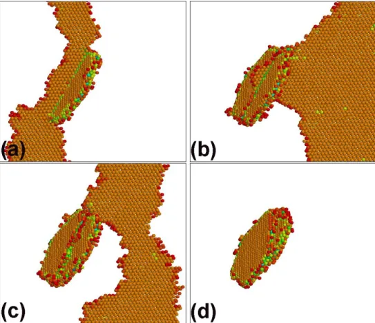
3.2.1 SD/W − configuration. The SD/W − configuration is shown in Fig. 4 in the case of two dis-locations in the simulation cell. In this configuration, the loop attracts the disdis-locations. When the first dislocation comes into contact with the loop border, it spontaneously cross-slips due to the elastic field of the loop. A D-Shockley partial is created on the loop border, that is mobile and progressively removes the double stacking fault of the loop (Fig. 4(a)). This mechanism was described in details in Ref. [11] and results in the absorption of the loop in the form of a helical turn on the screw dislocation (Fig. 4(b)). The applied stress required to form the helical turn is low, 40 MPa. The helical turn expands along the entire dislocation in order to minimize its length and the associated line tension energy. In this configuration, the dislocation does not belong to any specific {111} plane and is constricted along its entire length, since the helical turn has inherited the h121i contour of the initial loop, as seen in Fig. 4(b).
The helical turn is an obstacle that pins the first dislocation because it can glide only in the Y-Burgers vector direction and not the X-glide direction. As the applied stress is increased, the second dislocation approaches. The two dislocations repel each other since they have the same Burgers vector. The portion of the helical turn near the second dislocation rotates and becomes perpendicular to the latter (Fig. 4(c)). This configuration (with perpendicular dislocation segments) minimizes the elastic repulsion between them. The same effect is observed with repulsive dislocation junctions [36]. The rotation of the jogs implies a contraction of the helical turn and an extension of one arm of the first dislocation in an upper (1¯11) glide plane, where it locally dissociates, as seen in the upper part of Fig. 4(c). It is noted that the dissociated segment is systematically emitted from the second upper corner of the initial loop.
When the second dislocation comes into contact with the helical turn, the contact is punctual. The two dislocations spontaneously exchange arms, after which the helical turn is shared by the two dislocations, as seen in Fig. 4(d). Each jog now connects one segment of the first dislocation to another segment of the second dislocation. During this process, the upper dissociated arm continues to expand and bows out, being repelled by both the second dislocation and the applied stress. Then, this segment undergoes an Orowan process (Fig. 4(e)), unpins and leaves behind the second dislocation that now contains the helical turn (Fig. 4(f)).
The net result is the absorption of the Frank loop into the core of a screw dislocation and the transfer of the other dislocation through the initial helical turn with re-emission in an upper (1¯11) plane. This 1 2 3 4 5 6 7 8 9 10 11 12 13 14 15 16 17 18 19 20 21 22 23 24 25 26 27 28 29 30 31 32 33 34 35 36 37 38 39 40 41 42 43 44 45 46 47 48 49 50 51 52 53 54 55 56
For Peer Review Only
The reaction stress associated to the SD/W − configuration is 180 MPa. With only one dislocation in the simulation cell, unpinning also requires the activation of a dissociated segment in an upper (1¯11) plane, as observed in Nickel on loops with h110i borders [11]. The activation stress is higher in absence of the repulsion between the dislocations that favors the closing of the helical turn and repels the activated segment. The unpinning stress obtained with a single dislocation is 335 MPa, i.e. about twice that obtained with two dislocations. In this case, an unfaulted prismatic loop is left behind with the same Burgers vector as the dislocation, as presented in Ref [11].
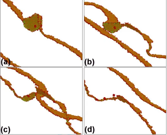
3.2.2 SD/W + configuration. Attention is now paid to the SD/W + configuration, shown in Fig. 6 with one dislocation in the simulation cell. This geometry is less favorable to cross-slip than SD/W − because, with respect to the orientation of this Figure, the right-hand arm of the screw dislocation has to cross-slip in the upper-half of the loop, while the left-hand arm has to cross-slip in the lower half. Because of the inclination of the loop, the length of the two arms increases in this process, which is energetically unfavorable. As a consequence, the dislocation does not cross-slip when it comes into contact with the loop (S− side, defined in section 2.1) but rather shears the latter until it reaches the S+ side of the loop (Fig. 6(a)). Loop shearing requires a low stress: 95 MPa. Because of the dislocation and loop symmetries, the configuration is then SD/W − and the dislocation spontaneously cross-slips (Fig. 6(b)). However, the applied stress drives the dislocation away from the loop and only one quarter of loop is unfaulted (Fig. 6(c)). The jogs created on the screw dislocation increase the effective loop size and decrease the length of the segment in the initial glide plane. This increases strongly the loop resistance and an applied stress of 250 MPa is required to unpin the dislocation (Fig. 6(d)). The loop is not unfaulted but simply sheared with the creation of a step on its surface that is visible in Fig. 6(d). This step is mobile on the loop surface and glides towards a border of the loop where it annihilates, leading to a healing of the loop. This reaction is labeled R1 (see below for details). Then, up to the fourth passage of the dislocation, no cross-slip at all is observed and a step with a height of 3b is created on the loop surface. During the fifth passage, cross-slip finally occurs after shearing, in much the same way as described above. However, unfaulting is again aborted and the dislocation unpins, leaving behind a loop with an upper half unfaulted, which rapidly heals-up once again. In conclusion, with only one dislocation in the simulation cell, no permanent damage is induced on the loop and the reaction is of R1-type.
When two dislocations are present in the simulation volume, as shown in Fig. 7, the stress field produced by the second dislocation in the cross-slip plane of the first dislocation helps the latter to cross-slip on the S− side of the loop (Fig. 7(a)) and to unfault the upper half of the loop. The latter becomes an half helical turn on the screw dislocation (Fig. 7(b)). The first dislocation is pinned by this helical turn and by the faulted half-loop. When the second dislocation comes into contact, an arm-exchange takes place in the same way in the SD/W − case. This enables a complete loop unfaulting and favors the activation of the dissociated segment in the central (1¯11) plane (Fig. 7(c)). The first dislocation thus unpins and leaves behind the second dislocation with a complete helical turn (Fig. 7(d)). When the first dislocation comes back through the periodic boundary conditions, an arm-exchange followed by an elevator effect occurs as described in previous section, the new emitted dislocation being in an upper (1¯11) plane. The resistance offered by the loop in this case is 180 MPa. Adding a second dislocation thus enables to fully unfault the Frank loop and to transform the latter into a helical turn on the screw dislocation.
http://mc.manuscriptcentral.com/pm-pml 11 12 13 14 15 16 17 18 19 20 21 22 23 24 25 26 27 28 29 30 31 32 33 34 35 36 37 38 39 40 41 42 43 44 45 46 47 48 49 50 51 52 53 54 55 56 57 58 59 60
For Peer Review Only
3.3 R1/R2: Shear
The last case to consider is a simple shear of the Frank loop. As seen in Table 2, the corresponding critical stress is moderate, around 100 MPa. Shearing can produce three kinds of steps on the loop depending of the configuration. When loops are in configuration CS, dislocation passage creates steps on the loop border only. For ED/CS configuration, permanent shearing (Reaction R2) was obtained up to 6b steps. However, for the SD/CS configuration, the presence of the steps seems to promote loop unfaulting, which occurs after two dislocation passages i.e. after a 2b step is created. If loops are in W + or W − configurations, the steps cross the whole loop surface. They may either be of interstitial-type (W − configuration) or vacancy-type (W + configuration). The step formation energy depends on the step nature, interstitial-type steps being more energetic and more mobile than vacancy-type steps. The former annihilate more rapidly than the latter that can survive during several dislocation passages and acquire a height of several Burgers vectors before annihilating (e.g. 3b steps in the SD/W + configuration discussed in Section 3.2).
The ED/W + case is shown in Fig. 8. The loop attracts the dislocation which aligns with the loop surface and remains close to an edge dislocation (Fig. 8(a)). The dislocation can not cross-slip and when the applied stress reaches 95 MPa, it shears the loop and unpins (Fig. 8(b)), creating a vacancy-type step on the loop surface. When the dislocation comes back onto the loop due to the periodic boundary conditions, it shears the loop again and creates a 2b step (Fig. 8(c)) that is mobile and annihilates on the loop border (Fig. 8(d)), thus healing the loop. The simulation was continued for 10 other dislocation passages, and after every passage or every other passage, the 1b or 2b steps annihilated on the loop border. The reaction is thus R1: no permanent damage is created on the loop. Only the loop shape was changed. It became more rounded after each dislocation passage by migration of interstitial atoms along the loop border.
Simulations were also performed at 300 K with Mishin potential in order to evaluate the influence of the temperature. In all configurations, except SD/W −, loop shearing was observed. As will be emphasized in the following Section, the reason for this is that all unfaulting reactions start by dislocation cross-slip. Therefore, loop unfaulting can be inhibited by cross-slip limiting factors such as a low temperature.
4 Discussion
An interaction matrix (Table 2) was established thanks to the simulations presented in previous sections. Three interaction mechanisms were observed: loop shearing (R1/R2), loop unfaulting and absorption in a glissile configuration (R3) and loop unfaulting and absorption in a sessile helical turn (R4). The interaction mechanisms are in close analogy with those obtained with SFTs [13,16]. The main difference between Frank loops and SFTs is that the latter can not be completely absorbed by moving dislocations. Also, because of the shape of SFTs with {111} faces and h110i wedges, the helical turns on screw dislocations and the superjogs on edge dislocations have dissociated structures that mostly belong to {111} planes. Besides these two points, unfaulting processes are similar for both types of defects and are controlled by cross-slip events. Loop unfaulting may therefore be inhibited by cross-slip controlling factors, that are discussed below. When unfaulting is impeded, in all cases, the interaction mechanism becomes loop shearing.
4.1 Parameters controlling the interaction mechanism
The main parameter that controls the occurrence of either shear or unfaulting is the relative configuration between the dislocation and the Frank loop. Edge dislocations unfault Frank loops only in the ED/W − configuration. In all other configurations involving edge dislocations, regardless of the number of disloca-tions in the simulation cell, the Frank loops are sheared. By way of contrast, screw dislocadisloca-tions unfault Frank loops in all configurations with two dislocations in the simulation cell and in all configurations except SD/W + with only one dislocation. Unfaulting is followed by absorption of the unfaulted section of the loop and can lead either to the formation of a helical turn on the screw dislocation line (configurations 1 2 3 4 5 6 7 8 9 10 11 12 13 14 15 16 17 18 19 20 21 22 23 24 25 26 27 28 29 30 31 32 33 34 35 36 37 38 39 40 41 42 43 44 45 46 47 48 49 50 51 52 53 54 55 56
For Peer Review Only
4.1.1 Temperature, stress-rate and stacking fault energy. Two distinct unfaulting mechanisms were observed. The first mechanism initiates when a screw dislocation segment interacts with a Frank loop in a wedge-type configuration. It creates a D-Shockley that sweeps and unfaults the loop. Simultaneously, the screw dislocation undergoes successive cross-slip events in order to accommodate the form of the loop border, aligned in h121i directions (see Fig. 4). The second mechanism is obtained when a mobile screw dislocation cross-slips and re-dissociates in the habit plane of the Frank loop which is then a cross-slip plane of the dislocation (see Fig. 3). The Shockley partials sweep one of the two stacking faults and have to react with the Frank partial on the loop border in order to complete the unfaulting process.
In the simulations, such reactions occur over time scales between 20 and 35 ps. If the stress-rate is too large, the applied stress exceeds the loop resistance before the unfaulting process is completed and loop shearing is obtained. In order to keep constant the applied stress while the dislocations react with the loop, a stress-rate that depends on the rate of reaction was implemented. If no reaction occurs during a fixed time, the stress is increased at a rate of 3.3 MPa.ps−1. Simulations were performed at higher stress-rates that favor shearing. For example, shear is obtained instead of unfaulting by using a constant stress-rate of 10 MPa.ps−1 in the configuration SD/W −. The same blocking effect can be obtained with deformation controlled boundary conditions by using a too high strain rate, as discussed in Ref. [16] in the case of SFTs.
In addition, since cross-slip is a thermally-activated process, unfaulting reactions can be impeded by applying a too low temperature. Simulations were performed with the Cu EAM potential developed by Foiles [35]. Shear was obtained in SD/W − configuration at 300 K whereas unfaulting was obtained at 600K. Therefore, unfaulting can occur only when the time the dislocation remains in contact with the loop (which is controlled by the stress-rate) is long as compared to the characteristic time needed for dislocation cross-slip (which is controlled by the temperature and the configuration).
The stacking fault energy (SFE) also plays a role in loop unfaulting since a low SFE means a large separation between partials and therefore, a lower cross-slip probability. In an attempt to clarify this point, simulations were performed with the Cu EAM potential developed by Foiles [35]. This interatomic potential predicts a low SFE (11.2 mJ.m−2) and shear was obtained in SD/W − configuration at 300 K, whereas unfaulting was obtained at the same temperature using Mishin potential. Also, in Ref. [11], a Ni EAM potential predicting a higher SFE (89 mJ.m−2) was used but with a lower temperature (100 K). In the case of Frank loops with h121i edges in SD/W − configuration, the passage of screw dislocations induced loop shearing.
4.1.2 Non-glide stresses. In MD simulations, the applied stress tensor is usually simple shear, whereas in actual materials, the stress state is usually far more complex due for example, to stress incompatibility in polycrystals, dislocation pile-ups or the loop environment. Realistic stress states thus include non-glide components, which can be of two types, each producing different effects on the unfaulting reaction. The shear stress component resolved in the glide plane perpendicularly to the dislocation Burgers vector can either increase or decrease the separation between the Shockley partials of a given dislocation, depending on the sign of the stress with respect to the dislocation Burgers vector. Thus perpendicular non-glide stresses can either favor or impede cross-slip. In order to check this point, the configuration SD/W − was considered. Foiles potential was used at 300 K, and a σZX = −1/2|σZY| stress was added to the simulation
cell so as to decrease the distance between partials. In this case, unfaulting was obtained instead of shearing. Similarly, Mishin potential was used at 600 K in the SD/W − configuration, with a σZX = 1/2|σZY| stress
http://mc.manuscriptcentral.com/pm-pml 11 12 13 14 15 16 17 18 19 20 21 22 23 24 25 26 27 28 29 30 31 32 33 34 35 36 37 38 39 40 41 42 43 44 45 46 47 48 49 50 51 52 53 54 55 56 57 58 59 60
For Peer Review Only
so as to increase the dissociation between the partials, and shearing was obtained.
The second type of non-glide stresses are those in the direction of the Burgers vector of a screw disloca-tion, but resolved in the cross-slip plane. These stress components directly affect the cross-slip probability. In simulations with two screw dislocations in the cell, the second dislocation produces such non-glide stresses. Indeed, in configuration SD/W + which is not favorable to the cross-slip of the screw dislocation (see Fig. 7), when two dislocations are present, the first dislocation cross-slips when it comes into contact with the loop, whereas when one dislocation is present in the cell, the dislocation shears the loop.
4.1.3 Loop size and density. When the distance between loops becomes too small, the dislocation cross-slips on the loop border and starts to unfault the loop, but unfaulting stops because the dislocation line length between the loops is too short to accommodate the change of glide plane. For example, in configuration SD/W − with a 6 nm loop, when the distance between loops is 12 nm instead of 50 nm (i.e. when the loop density increases), loop shearing is obtained. Similarly, in configuration SD/W − with an inter-loop distance of 25 nm, when the loop size increases from 6 nm to 12 nm, we go from unfaulting to shearing.
In conclusion of this section, we can say that, since the strain rate in MD simulations is much faster than in real experiments, a complex reaction taking place in a simulation will most probably occur in actual experimental conditions. On the other hand, when loop shearing is observed, it is difficult to predict with MD only, whether or not a smaller strain rate (that would provide a contact time consistent with the time scale of thermally activated processes) can change the nature of the interaction.
4.2 Critical unpinning stresses
The decrease in the unpinning stress is not inversely proportional to the number of dislocations in the cell, as would be excepted from the usual pile-up effect [37]. As seen in Table 2, the relative decrease of the loop strength varies from 22 to 31 %, except in the SD/W − configuration where the arm exchange induces a diminution of 46 %. Dislocation Dynamics results indeed showed that in the case where the obstacles have a finite size, unlike the usual case of an infinite grain boundary, the stress is not inversely proportional to the number of dislocations in the cell [38].
Critical unpinning stresses were obtained for an inter-loop distance of L = 50 nm. In order to obtain the critical unpinning stress dependence with L, simulations with different inter-loop distances are required. However, it has been checked that Orowan’s law is verified for strong obstacles in MD simulations [11, 39]. Thus, the interaction coefficients for the different simulated configurations can be estimated thanks to the relation α = τcL/µb, where µ = 41 GPa is the shear modulus in {111} planes and b = 0.2556 nm the
magnitude of the Burgers vector. The values obtained are given between parenthesis in Table 2. These coefficients have the advantage of accounting for the fact that the elastic shear modulus of the present Cu potentials is about half that of SS. As a result, critical unpinning stresses in SS are expected to be higher than those reported here: the use of the present interaction coefficients for SS gives a maximum resistance as high as 1.59 × 75 GPa×0.26 nm/50 nm ∼ 600 MPa, of the order of the critical twinning RSS at 600K (= 2 × 35 mJ.m−2/1.45 ˚A ∼ 500 MPa), which could explain why twinning is locally observed, even at 600 K [27, 28]. Note that the critical twinning stress does not depend on the shear modulus. In our matrix, it should be noted that some of the interaction coefficients are larger than 1, particularly when helical turns are present. This effect comes from the fact that the controlling unpinning reaction is then the activation of a segment with a length lower than L and thus, with an Orowan stress larger than µb/L.
Table 2 shows that the strongest obstacles are associated with helical turns (SD/W − and SD/W +). Intermediate obstacles are when the loops are partially or fully unfaulted and absorbed under the form of glissile jogs (ED/W −, SD/CS). The weakest configurations are associated with loop shearing (ED/W +, ED/CS) whereby reduced damage is created on the loops and no jog forms on the dislocations. In all configurations, edge dislocations are less pinned than screw dislocations.
1 2 3 4 5 6 7 8 9 10 11 12 13 14 15 16 17 18 19 20 21 22 23 24 25 26 27 28 29 30 31 32 33 34 35 36 37 38 39 40 41 42 43 44 45 46 47 48 49 50 51 52 53 54 55 56
For Peer Review Only
exchange (Fig. 4(d)) and the dissociated segment expands spontaneously in its upper glide plane. With shorter loop separations (L = 25 nm), the structure is stable after arm-exchange, and the applied stress has to be increased further to activate the dissociated segment. In the case of very large distances, the dissociated segment should even be activated before the arm exchange takes place. The final structure is however the same, with the second dislocation acquiring the helical turn. A more systematic and detailed study by Dislocation Dynamics of the resistance of full and shared helical turns between two dislocations is underway [38].
4.3 Edge versus Screw dislocations
The unpinning stress of edge dislocations is lower than that of screw dislocations in all configurations. Edge dislocations shear Frank loops in two configurations out of three, and in configuration ED/W −, unfaulting and absorption are only partial, since half of the faulted loop is left behind after unpinning. The clearing of a glide plane by edge dislocations is thus expected to be very gradual. Moreover, an edge dislocation can not widen a clear band because it would require to activate the segment between the two superjogs created by the loop absorption. The corresponding stress is very high since this segment has a length of the order of the loop size, ∼ 5 nm, and can not expand as in the case of helical turns, because the superjogs can not glide away from each other (that process would require absorption of new interstitial atoms).
The situation is different with screw dislocations. Their unpinning stress is larger but they systematically unfault the loops and can therefore clear a glide plane. When they react, they acquire a helical turn that is the strongest possible obstacle because it spreads along the entire dislocation thanks to the mobility of the superjogs along the dislocation line. In a pile-up, we therefore expect the leading dislocation to be pinned. This dislocation can serve to broaden the clear band by the elevator effect described above, which allows the following dislocations in the pile-up to be transferred in an upper {111} plane. The critical transfer stress is reduced by the mobility of the superjogs along the dislocation line that glide away from each other and produce a long dislocation segment with a low Orowan stress. Note that with the elevator effect, since the new dislocation is systematically emitted from the same corner of the Frank loop, the clear band broadens only on one side of the glide plane, which corresponds with the present notations to the side of positive Z coordinates.
From the difference in pinning strengths between screw and edge dislocations, a dislocation loop in a shear band is expected to expand preferentially in the direction of its Burgers vector. The dislocation structure should therefore be anisotropic, with long screw segments that will create and widen the clear band. This conclusion is consistent with the in-situ TEM observations of Robach et al [6] that found only screw dislocations in clear bands. They consider deformed irradiated copper crystals where the irradiation defects are mainly SFTs, but we have already noted the strong analogy between SFTs and Frank loops. The figure 3 (a) of Ref. [6] shows a group of elongated dislocation loops with long and wiggled segments that, according to the g vector and the (111) slip trace of the band, are [¯101] screw dislocations. Note that in in-situ TEM, due to the thin foil geometry of the samples, the superjogs that form on the screw dislocations can glide to the nearby free surfaces and eliminate, thus healing the dislocations that can keep gliding. As in the present simulations, we expect that the dislocation segment that pushes the superjogs will be in an upper {111} plane and will broaden the clear band. The fact that this dislocation is re-emitted on a plane lying in the upper corner of the Frank loops also implies that slip lines are separated by a distance of the order of the size of the irradiation defects, which is consistent the distance of 4 nm
http://mc.manuscriptcentral.com/pm-pml 11 12 13 14 15 16 17 18 19 20 21 22 23 24 25 26 27 28 29 30 31 32 33 34 35 36 37 38 39 40 41 42 43 44 45 46 47 48 49 50 51 52 53 54 55 56 57 58 59 60
For Peer Review Only
between slip lines obtained by Neuha¨user in irradiated copper [40].
5 Conclusion
A systematic study of edge and screw dislocations in interaction with Frank loops was performed. We found that screw dislocations are more efficient than edge dislocations to unfault loops, permit clear band widening but are strongly pinned by the formation of extended helical turns.
There remain many open questions regarding clear band formation and the passage from nanometric to micronic scales. For instance, from the difference in behavior between screw and edge dislocations observed in MD, anisotropic dislocation microstructures are expected in clear bands. Moreover, the screw dislocations pinned by helical turns should remain in the clear bands, even after unloading. However, this could be an artefact of the MD simulations where the dislocations have short lengths and are forced to keep their initial character. At the micron-scale, large dislocation loops can form and the superjogs on the screw parts can be pushed to the edge parts where they can be dragged away, thus freeing the screw parts. In order to clarify this point, we have undertaken a study using Dislocation Dynamics based on the interaction matrix developed here [38].
This work was funded by the European PERFECT project (No. FI60-CT-2003-508840). The authors wish to thank Prof. Yves Br´echet and Dr. Marc Fivel for numerous and stimulating discussions.
References
[1] K. Farrell, T. S. Byun and N. Hashimoto, J. Nucl. Mater. 335 (2004) 471. [2] B. N. Singh and S. J. Zinkle, J. Nucl. Mater. 206 (1993) 212.
[3] M. Victoria, N. Baluc, C. Bailat, Y. Dai, M. I. Luppo, R. Schaublin and B. N. Singh, J. Nucl. Mater. 276 (2000) 114. [4] M. Suzuki, A. Sato, T. Mori, N. Nagakawa and H. Shiraishi, Phil. Mag. A 65 (1992) 1309.
[5] J. V. Sharp, Phil. Mag. 16 (1967) 77–96.
[6] J. S. Robach, I. M. Robertson, B. D. Wirth and A. Arsenlis, Phil. Mag. 83 (2003) 955. [7] Y. Matsukawa and S. J. Zinkle, J. Nucl. Mater. 329-333 (2004) 919.
[8] Y. Matsukawa, Y. N. Osetsky, R. E. Stoller and S. J. Zinkle, Mater. Sci. Eng. A 400-401 (2005) 366. [9] R. Schaublin, Z. Yao, P. Spatig and M. Victoria, Mater. Sci. Eng. A 400-401 (2005) 251.
[10] D. Rodney and G. Martin, Phys. Rev. B 61 8714(2000) . [11] D. Rodney, Acta Mater. 52 607 (2004).
[12] B. D. Wirth, V. V. Bulatov and T. de la Rubia, J. Eng. Mater. Technol. 124 329 (2002).
[13] Y. N. Osetsky, R. E. Stoller, D. Rodney and D. J. Bacon, Mater. Sci. Eng. A 400-401 370 (2005) . [14] P. Szelestey, M. Patriarca and K. Kaski, Model. Simul. Mater. Sci. Eng. 13 541 (2005).
[15] J. S. Robach, I. M. Robertson, H. J. Lee and B. D. Wirth, Acta Mater. 54 1679 (2006). [16] Y. N. Osetsky, D. Rodney and D. J. Bacon, Phil. Mag. 86 2295 (2006).
[17] S. M. Bruemmer, E. P. Simonen, P. M. Scott, P. L. Andresen, G. S. Was and J. L. Nelson, J. Nucl. Mater. 274 299 (1999). [18] C. Pokor, Y. Br´echet, P. Dubuisson, J. P. Massoud and A. Barbu, J. Nucl. Mater. 326 19 (2004).
[19] G. S. Was and J. T. Busby, Phil. Mag. 85 443 (2005). [20] G. E. Lucas, J. Nucl. Mater. 206 287 (1993).
[21] J. E. Pawel, A. F. Rowcliffe, G. E. Lucas and S. J. Zinkle, J. Nucl. Mater. 239 126 (1996). [22] C. Pokor, Y. Br´echet, P. Dubuisson, J. P. Massoud and X. Averty, J. Nucl. Mater. 326 30 (2004). [23] T. S. Byun, Acta Mater. 51 3063 (2003).
[24] J. A. Venables, Phil. Mag. 6 379 (1961).
[25] M. Niewczas and G. Saada, Phil. Mag. 82 167 (2002).
[26] J. I. Cole and S. M. Bruemmer, J. Nucl. Mater. 225 53 (1995).
[27] C. Bailat, A. Almazouzi, N. Baluc, R. Schaublin, F. Groschel and M. Victoria, J. Nucl. Mater. 283–287 446 (2000). [28] N. Hashimoto, S. J. Zinkle, A. F. Rowcliffe, J. P. Robertson and S. Jitsukawa, J. Nucl. Mater. 283–287 528 (2000). [29] R. M. Latanision and A. W. Ruff, Met. Trans. 2 505 (1971).
[30] T. S. Byun, J. Nuc. Mat. 303 34 (2002).
[31] Z. Yao, R. Schaublin and M. Victoria, J. Nucl. Mater. 329-333 1127 (2004). [32] Z. Yao, R. Schaublin, P. Spatig and M. Victoria, Phil. Mag. 85 745 (2005).
[33] Y. Mishin, D. Farkas, M. Mehl, D. Papaconstantopoulos, A. Voter and J. Kreuss, Phys. Rev. B 63 224106 (2001). [34] R. E. Schramm and R. P. Reed, Met. Trans. A 6 1345 (1971).
[35] M. Foiles, M. Baskes and M. Daw, Phys. Rev. B 33 7983 (1986). [36] D. Rodney and R. Phillips, Phys. Rev. Lett. 82 1704 (1999).
[37] J. P. Hirth and J. Lothe, Theory of Dislocations (Krieger, Malabar, 1992). [38] T. Nogaret, D. Rodney and M. Fivel, to be submitted.
[39] Y. N. Osetsky, D. J. Bacon and V. Mohles, Phil. Mag. 83 3623 (2003).
[40] H. Ne¨uhauser, in: N. Nabarro (Ed.), Dislocations in Solids, Vol. 6 (North-Holland, Amsterdam, 1983).
1 2 3 4 5 6 7 8 9 10 11 12 13 14 15 16 17 18 19 20 21 22 23 24 25 26 27 28 29 30 31 32 33 34 35 36 37 38 39 40 41 42 43 44 45 46 47 48 49 50 51 52 53 54 55 56
For Peer Review Only
Figure 1. Schematic representation of the simulation cell (a) and notations for the description of the configurations (b).
Figure 2. Configuration ED/W − with one dislocation (1ED, B−, S−, P 1): snapshots shown at 65 MPa, 50 ps (a), 105 MPa, 70 ps (b), 130 MPa, 88 ps (c), 130 MPa, 100 ps (d), 130 MPa, 102 ps (e), 130 MPa, 102 ps, with a different viewing angle(f).
http://mc.manuscriptcentral.com/pm-pml 11 12 13 14 15 16 17 18 19 20 21 22 23 24 25 26 27 28 29 30 31 32 33 34 35 36 37 38 39 40 41 42 43 44 45 46 47 48 49 50 51 52 53 54 55 56 57 58 59 60
For Peer Review Only
Figure 3. Configuration SD/CS with one dislocation (1SD, B−, S−, P 3): snapshots shown at 80 MPa, 60 ps (a), 100 MPa, 72 ps (b), 125 MPa, 162 ps (c), 135 MPa, 170 ps (d), 150 MPa, 175 ps (e), 160 MPa, 200 ps (f).
1 2 3 4 5 6 7 8 9 10 11 12 13 14 15 16 17 18 19 20 21 22 23 24 25 26 27 28 29 30 31 32 33 34 35 36 37 38 39 40 41 42 43 44 45 46 47 48 49 50 51 52 53 54 55 56
For Peer Review Only
Figure 4. Configuration SD/W − with two dislocations (2SD, B−, S−, P 1): snapshots shown at 5 MPa, 15 ps (a), 40 MPa, 89 ps (b), 180 MPa, 148 ps (c), 180 MPa, 153 ps (d), 180 MPa, 165 ps (e), 180 MPa, 169 ps (f).
http://mc.manuscriptcentral.com/pm-pml 11 12 13 14 15 16 17 18 19 20 21 22 23 24 25 26 27 28 29 30 31 32 33 34 35 36 37 38 39 40 41 42 43 44 45 46 47 48 49 50 51 52 53 54 55 56 57 58 59 60
For Peer Review Only
Figure 5. Two screw dislocations in presence of both W − and W + loops (2SD, B−, S−, P 1andP 2): snapshots shown at 195 MPa, 140 ps (a), 200 MPa, 145 ps (b), 205 MPa, 155 ps (c), 210 MPa, 165 ps (d), 215 MPa, 163 ps (e), 215 MPa, 193 ps (f).
1 2 3 4 5 6 7 8 9 10 11 12 13 14 15 16 17 18 19 20 21 22 23 24 25 26 27 28 29 30 31 32 33 34 35 36 37 38 39 40 41 42 43 44 45 46 47 48 49 50 51 52 53 54 55 56
For Peer Review Only
Figure 6. Configuration SD/W + with one dislocation (1SD, B+, S−, P 1): snapshots shown at 95 MPa, 63 ps (a), 110 MPa, 75 ps (b), 205 MPa, 112 ps (c), 250 MPa, 138 ps (d). http://mc.manuscriptcentral.com/pm-pml 11 12 13 14 15 16 17 18 19 20 21 22 23 24 25 26 27 28 29 30 31 32 33 34 35 36 37 38 39 40 41 42 43 44 45 46 47 48 49 50 51 52 53 54 55 56 57 58 59 60
For Peer Review Only
Figure 7. Configuration SD/W + with two dislocations (2SD, B+, S−, P 1): snapshots shown at 75 MPa, 50 ps (a), 180 MPa, 88 ps (b), 210 MPa, 102 ps (c), 210 MPa, 110 ps (d). 1 2 3 4 5 6 7 8 9 10 11 12 13 14 15 16 17 18 19 20 21 22 23 24 25 26 27 28 29 30 31 32 33 34 35 36 37 38 39 40 41 42 43 44 45 46 47 48 49 50 51 52 53 54 55 56
For Peer Review Only
Figure 8. Configuration ED/W + with one dislocation (1ED, B+, S−, P 1): snapshots shown at 55 MPa, 75 ps (a), 95 MPa, 108 ps (b), 95 MPa, 155 ps (c), 95 MPa, 165 ps (d). http://mc.manuscriptcentral.com/pm-pml 11 12 13 14 15 16 17 18 19 20 21 22 23 24 25 26 27 28 29 30 31 32 33 34 35 36 37 38 39 40 41 42 43 44 45 46 47 48 49 50 51 52 53 54 55 56 57 58 59 60


![[PDF] Cours complet sur ASP.Net pour aller plus loin | Cours informatique](data:image/gif;base64,R0lGODlhAQABAIAAAP///wAAACH5BAEAAAAALAAAAAABAAEAAAICRAEAOw==)