HAL Id: in2p3-00666088
http://hal.in2p3.fr/in2p3-00666088
Submitted on 3 Feb 2012
HAL is a multi-disciplinary open access
archive for the deposit and dissemination of
sci-entific research documents, whether they are
pub-lished or not. The documents may come from
teaching and research institutions in France or
abroad, or from public or private research centers.
L’archive ouverte pluridisciplinaire HAL, est
destinée au dépôt et à la diffusion de documents
scientifiques de niveau recherche, publiés ou non,
émanant des établissements d’enseignement et de
recherche français ou étrangers, des laboratoires
publics ou privés.
L. Bex
To cite this version:
L. Bex. Review of latest developments of ions sources. EPAC 92 - Third European Particle Accelerator
Conference, Mar 1992, Berlin, Germany. pp.252-256. �in2p3-00666088�
Review of Latest Developments of Ion Sources
Lucien Bex
GANIL, BP 5027
F- 1402 1 Cam cedex
Abstract
This review will summarize the major technical advances in the field of ion sources during the last years; this topic is frequently reviewed and it is the focus of international conferences (e.g. ICIS 91 in Bensheim, Germany, Sept. I99 I) or specialize:d workshops. Developments of ion sources are stimulated by the numerous applications which can largely be grouped into major areas like particle accelerator injection, ion implantation, lithography, surface processing, isotope separation, neutral be,ams for fusion plasma heating and thrusters for electric space propulsion. In this review paper
emphasis is put on recent developments of ion sources for particle accelerator injection. The latest trends in development are also given.
1.
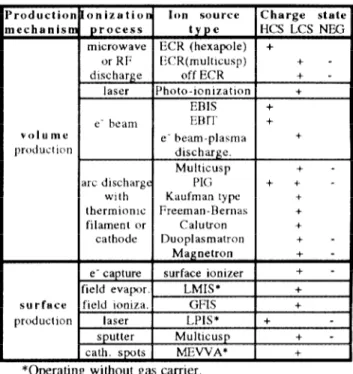
INlROIXJCI’IONThe topic of ion sources is so vast that the latest develop- ments thereupon cannot be reviewed in detail in the brief space available here, therefore the views exposed will necessarily be selective. First of all the apparent diversity of ion sources must be reduced by finding relations between them. Table I is an attempt to classify ion sources which are well known by their acronym The meaning of these acronyms will be given further on in the text. They can be divided into three categories according to the charge state of the extracted ions, i.e. high (HCS). low (IXS) and negative (NEG) charge states. They can also be grouped according to the ionization process: the energy carrier being electrons, photons, high electric fields, high-energy ions sputtering a low-work-function metal surface for producing negative ions or a hig]~-work-function met& surface ionizing atoms (e.g. 1.i on W at 12oOY’).
Arc discharges, where electrons arc generated from ther- mionic lilaments, are progressively replaced by microwave discharges where electrons are continuously generated and heated. Furthermore, a microwave plasma cathode has been developed and adapted to a well-known Kaufman source [ I].
IIigher charge states with moderate intensities can now be produced with ERIS, IPIS or F(‘R sources. Even very high charge states (23RLJ67+), which could until now be generated only by stripping of high-energy ion beams, have been crti?tctl at very low intensity in a new source called EBIT.
By increasing the magnetic field near the wall of the source chamber, the plasma density can be one or two orders of magnitude higher. This is achieved by covering the walls with permanent magnets, creating a “minimum 0” magnetic configuration which confines the plasma. For ECR sources an hexapole is used, for others called “multicusp” ion sources, the walls are covered with permanent magnet bars.
1 Iigh-current beams of metal ions at low-charge states can
Table 1. Ion source classification by ionization process Ion source Charge state HCS LCS NE
microwave ECR (hexapole) +
or RI’ ITR(multlcusp) + - discharge off ECR + -
laser Photo-ionization + ERIS + e‘ heam EBIT + volume em beam-plasma + jmKlucticw discharge.
Multicusp + - arc discharge I’K ++ -
with Kaufman type + thermionic Freeman-Rernas + filament or Calutron +
cathode Duoplasmatron + -
1 Mukcusp 1 + - cath. spots 1 MEWA* +
. .
-operaung wltnout gas carrier.
now be generated with new sources (I.MIS, I,PIS and MEVVA) working without gas carrier
Negative ion be:uns have been improved from several mA to more than 1 A in just twenty years and they are becoming more and more important for applicationc m accelerators, tokamak reactors and ion implanters.
A recent book entitled “The l’hyslcs and Technology of Ion Sources” gives il review of existing ion sources [2].
2. HI(;II-CI~AR(;IJ-s~‘A’I‘I’ ION SOI IRCES 2. I Electrwn-Beum Ion Trup (E/117>
This source [3], which is a variant of the EUIS has been recently developed for studying interactions of fast electrons with highly charged ions. The lXL31’1‘ (Fig. I) consists of an electron beam compressed to current densities of up to 6000 Ncm2. lbe electron beam radius is maintained at around 30 pun by the field (R = 3 T) of two superconducting Helmholtz coils. The ion trap is a drift tube which has a length of 20 mm. The electron-beam energy is operated at up to 30 keV and will be upgraded up to 150 keV. Ions are introduced into the trap either by injection from an auxiliary ion source or through ionization of the background gas. For metallic ions the auxiliary source is a MEVVA, which injects ions axially into the trap. Table 2 shows the preliminary performance of this new source.
Figure 1. Schematic diagram of the E:,RIT.
ion
23zTh80+
238u67t
Table 2
number electron trappIng of particles beam energy time
per pulse (keV) (s)
2.10? 24 3
1.10” 9 4
2.2 Electron-Beam Ion Sor4rces (HtlS)
The progress in increasing the intensity of very high- charge states is slow bccause of the relatively complicated technology of ERIS constn~ction. Nevertheless, an important breakthrough has been achieved by low-charge-state ion injection and by “ion-by-ion” cc~)ling. With an e- beam ener- gy of 50 keV, XC++ and Xe54+ have been detected in Dubna [4]. Table 3 showt results obtained with DionC at LNS 151.
Table 3
ion pulse duration peak beam emittance(4KMS) (FWHM) (ps) c.urrent (p.4) (n.mm.mrad)
12714'+ 15 0.3* 0.33
&1,@+ 2s 6.3 0.33
40~~16+ 2s 6 6 0.33
61 .i’+ IS 20 0.33
* 3.10) charges per pulse - repetition rate : 0.5 IJz
DionC is a cryogenic 1:HIS into which primary low-charge- state ions, produced by a duoplasmatron or a surface- ionization source, ‘arc injected. The hI,i3+ mentioned in table 3 is a polarized ion beam. While in the trap, the ions gain energy from the electron beam though electron-ion Coulomb collisions and UEV can escape from the trap. By injecting 2. 107 He atoms/c&Ii into the ionization zone, a cooling effect
on the high-charge-state ions takes place. Thereby the confinement time and the eleclron beam intensity arc increased and the yield of R“Kr7(1+ is doubled.
2.3 Electron-C,:clotron- liesoruln~~e Ion .Sources (l:‘Clil
Presently JI(:R ion sources are used at some 2.5 laboratories all over the world. Interesting remarks at the last Workshop on JX‘R ion sources (Knoxville, Tennessee, Nov.,
1990) have been made by R. Geller 161 and A.G. Drentje 171. In 1979 an important breakthrough was achieved by the availability of hard permanent magnetic materials like
7
Sm( Ok, used to build hexapolc magnets wilhout electric
power. Tliese magnets arc able to produce the necessary mag- l:i,qurc 3. Schenzrtic _ view of NJ3)MAFJOS 10 (;JJz
netic field (BECK= 0.36 T) on the closed heating surface in the plasma at 10 GHz. More recently SmCo5 is being replaced by Nd-Fe-B, which gives a higher magnetic field and the ncccssary 13 value (BJ;cR= 0.51 T) to use the 14 GHz generators which are presently applied in satellite communication and therefore produced at a reasonable price.
Since higher charge states are obtained by increasing the microwave frequency and the magnetic field, a superconducting ECR ion source, which will cover the range from 6.4 to 28 GHz, is being constructed at MSU [81.
‘Ihe size of the plasma chamber of the new sources has been considerably reduced by increasing the microwave frequency and the magnetic lield.
The ion current is increased by a factor of 2.5 using an electron gun in order to inject electrons axially into the plasma (Fig. 2) [9]. By coating the plasma chamber wall with SiOz [9] the source performance is also improved, but this effect decreases after 10 hours.
b 1 -r---. -r- -r-v. 20 40 80 T- :- 80 I 1oOCm
Figure 2 Schematic drawing of the LRJ, advanced ECR ion source (14 GJ Iz) using an electron gun.
lisually high-charge-state beam currents are substantially increased when a lighter gas is mixed into the plasma. Observing that gas mixing, in general, has the effect of reducing the energy spread of extracted beams, T.A. Antaya tried a model [lo] for this effect based on “ion cooling”.
Metallic ions are produced by heating a solid sample directly in the plasma or by evaporating a piece of metal in an oven. A very expensive isotope such as 3RCa has been accelerated [ 111 at a very low consumption rate (2 mg/h).
In pulsed operation mode, high-currents of high-charge- state ions are obtained during the 1 ms afterglow [ I2- 131.
A new source (NlZOMAFIOS 10 GIIz) [ 14-391 (Fig 3) has been constructed in Grenoble entirely with Nd-Fe-B pcnnane~~~
magnets which have a remanent field of 1.2 T. The total electric power consumption is only 6 kW and the performances are similar to those of the classical IO GIl7.
sources. Oak Ridge has presented a proposal [ 151 to install such a SOLUC~ in the terminal of the tandem electrostatic
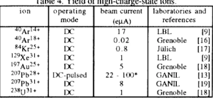
accelerator at 24 MV. Some remarkable new achievements which were reported recently are shown on table 4
Table 4. Yield of high-charge-state ions.
operating beam current laboratorIes and mode WA) references
DC 17 LBL 191
0.02 Grenoble [ 161 0.8 Jiilich 1171
DC 1 LL(L
LSI
Ix1 5 Grenoble [ 181
DC-pulsed 22 loo* GANII 1 [I31 DC 8 GANII. (191 DC 1 Grenoble [ 1 R]
*Afterglow (0.5 ms) in pulsed mode (50 ms -7 Hz)
Table 5 shows emittance measurements performed with light ions from gases like Hz and He at 90% of the total beam current. The extraction voltage is 7 kV for II*+ (/3=2.73 10-3),
15 kV for He+ @=2.X2 IO-?) and 40 kV for II+. Table 5.
:I.
NEW
METAL ION SOlJRCES3.1 Field emission Liquid Metal Ion Sorrrces (Lh4I.S’)
The LMIS [23] is composed of a thin needle substratum which is coated with a liquid mct;tl (Fig. 4).
(a)
(b)
Figure 4. (a) Diagram of the ion beam focusing system (b) lmpregnated-electc-type l.MIS
A potential of several kV is applied between tbe needle and
ati extraction electrode in ;1 vacuum better than lW7 mbar.
The electric forces cause the liquid surface to form a conical shape at the needle apex from which ions are emitted. The needle-poinl emission site has a tip radius estimated in the range of 10 to 100 nm and ;i surface electric field at the tip radius in the range of IO7 V/m.
A metal ion beam current from 10 to I(x) PA with a charge state of on0 or twc) c;ul be extracted. ‘Ihc energy Spreiid
is less than 10 eV and the ion temperature as low ilS 1 eV.
‘Ihe LMlS emittance is extrattrdiniuy low due to the small
surface of the emission point and the low ion temperature. The focused beam size, reaching 0.5 pm, IS only limited by chromatic aberrations. 1,ifetimes of several 100 hours with stable beams ‘are obtained.
Recently an impregnated-electrode-type l,MlS has been developed (Fig. 4 b). The porous tip is made of refractory metal, typically tungsten, by sintering a mixture of powders with granule diameters of 10 ‘and 100 pm The ion source has a cylindrical reservoir made of tungsten which is heated for melting the metal that is to be ionized. The flow rate of liquid met,als, whose vapor pressure al their melting point is as high as 10-j mTorr (Cu, Ag), can be controlled by the porous region. The number of emission points has been increased up IO eight and it has been shown that the ion current is proportional to this number.
The LMIS has found applications in a number of new technologies, e.g. beam lithography, submicron focusing, maskless implantation, thin film deposition, surface analysis and electrostatic space propulsion. The gaseous field ion source (GFIS) is a similar source operaling with gases.
3.2 Melal Vapor VUCUIIIII Arc ion .wurce.s (Mk’VVA)
The Ml3’VA ion source (l+‘ig 5) 1241 is a new kind of source in which a metal vapor arc without gas carrier is used as the plasma medium from which Ule ions arc extracted.
A trigger electrode initiates the discharge by a 4 ps wide and 12 kV high voltage pulse. Micron-sized spots in which the current density can be over lo6 A/cm2 appear on the cathode surface, where material is vaporized and ionized. Individual spots have been observed to move around on the cathode surface, each generating a few amperes of current. A strong pressure gradient causes the plasma generated witlrin the spot to plume away from the surface. This source can be operated with an arc current of 150-3.50 A with a 0.25 ms pulse width and a repetition rate of 15 pulses per second. The maximum peak ion current produced is 3.5 A for an extraction voltage of 80 kV and an extraction hole diameter of 10 cm.
rArcl ,- Extractor -,
Recently some novel features have been incorporated, namely the ability to switch between up to 18 separated cathode materials and UK conslruction of two sources, a broad
beam version with a 50 Cm dkamcter exlractor and 3 Ininiaturc
version of “thumb size”.
T3e~llS of solid IIIetidliC c1ement.s Nd SOIIle IIXtiIlliC AlOyS
have been produced with t.his source which is finding application for met;Ulurgical ion implanlation.
3.3 Laser-l~lmnu Ion Sources (LYIS)
The future of ‘tlIi5 sowu. provi&IIg in pulw.1 mode high
peak currents of lligh-ChXge-Stiltc: ions from a small SpN
could be very promising. Some laboratories begin to investigate lhe feasibility of using I,PIS for future accelerators (see table 6) and for ion implantation (2Sj dzvtjted to surface
modification. Commercially available machines for ion beam analysis (resolution: 100 nm) are built in the I Ikrainc.
ion S2C:rl 3+ 7Li?+ 207pQht 56~~3+ 181~,?1+ 12c?+ peak beam currrn1~;p.K) and pulse I length (Us\ T * (3 <;eV/u) 10’3 0.1 (dvzrase s (400 kV) 2 7 s laser p’w”’ density (W/CIl12) ‘ep, rate (Hz) Iaboralories. applications and references 1.10” 2.10” 3.10” 6.10’ 4.101’ 1.10” I.3 1 2s .2s i 50 JINR(Dubna) 1 I200 cyclotron [27] C’ERN test bench [28]
Van de Graalf
lest hen&
UNIV. of Arkansas
When a laser beam is focused upon lhc surface of a solid target on a spot diameter smaller than 200 pm with a power density greater that IOx W/cm2, matter is vaporized and then highly ionized. A plasma rapidly expands perpendicularly tcl the target surface and UK highest charge states produced XC projected into a small angle. The Charge state multiplicity anti
the mm iw kinetic energy (10 keV for ;I prwcr density 01 10’ 2 W/cm*) increase with the laser power density 011 the
t,arget. ‘Ihe emitt;uice of Uic extracted beam should be small, due to the small diameler of the spot on Ulc target.
The major drawbacks of this sowm XC lhc low rcpctition rate (50 Ilz) ,uid the large energy spread of the ions which is of the sanle order of magnitude as the tnc’an ion kinetic energy Moreovcr, craters having diameters near 3(X) ,~m are produced after about 100 shots 011 a SkItiC target and ii
degradation of the ion output occurs ; therefore the target must be rotated. I lscrs trf I ,PIS utilire two kinds of laser : Nd-Y A(; and CO2 lasers opcraling a( 1.06 and 10.6 111n wavelength respectively. Recently, the ion currenla were enhanced by electron injection in thr plasma to compcnsa~e for rhe space charges (301.
4.
NEGA’I’IVI: ION SO1 JK(‘I’S4. I Negative Hydrogen und Ueu~eriww Ion Sortrces
Negative hydrogen ions [32] have been used for several decades in tandem Van de Graaff accelerators where lhey are accelerated Lo a high potential, stripped lo protons and accelerated to ground, gaining an energy twice the potential.
They ah have been r~sed ill cyclo~rolls where CxlraCtiOn ih
achieved by stripping ll- ions. Duoplasmatron, Magnetron and PIG source studies are being pursued for these types of accelerators. New sources with a magnetic multipole bucket
Chamhcr and ~&tl “multicusp sources” are intensively studied for fusion programs and modified versions of these sources arc used for accelerators (IAMPF, KEK, ‘I‘KII IMI:, BNL, etc.).
Multicusp sources can produce a large volume of uniform and quiescent plasma; they are divided into two types: Surface- conversion and volume-producUon ion sources and arc desig- ned for IX‘ operation delivering more than 1 A of II- or D-.
‘he vc)lume-prcxiuction of If’ was dcmc~nslralcd in 1979 by a French group at Ecole Polyteclmique near Paris; this group is pursuing this development (4C)J.
Ic is well known that the injection 01‘ cesium enhances by a factor of 4 the production of II- or I-)- in the multicusp sour- ces, but it conlaminates the accelerator leading lo possible breakdowns. The surf~lcr-ct,nvcrsic,n source produces negative ions with transverse temperatures in the range of 5 to 10 eV compared with 0.5 to I eV for the volume-prtduction one, thus giving smaller emittances.
In surface-conversion sources the negalivc ions are pro- duced by single-electron capture performed by absorbed neutral aLoms or double-electron capture of reflected positive ions on a low-work-function surface, such as a monolayer of ccsium or a bulk of barium metal. In these sources cesium coated molybdenum converters are replaced by solid barium
converter isolation
valve (load lock)
13gure 6. Schematic d~agmm of the 1.131, barium
converter surface-production source (XBIJI IY-2009) ci!nvcrters, barirmt being a much less volatile marerial. Such sourct’s (Fig.C) are developed at 1,HI. [33] lo produce bigh-
intenxity in btcady-state Ii- or I)- bcmIs lo be used for the
next generation of tokamak reactors. The LRI, prototype products 145 mA of I.>- with a 10 cm diameter converter.
In vvlunle-prc)duction sources the negalive ions are produced directly within the plasma discharge via dissociative attachment of vibrationally excited molecules. When they are operated without cesium vapor, the high pressure (10 m’I’orr) in these sources results in a signilicanl beam loss due to
stripping of Ihe ncgaCvc ions and in a large amounl of leakagc e- mixed into the negative ion beam. The lifetime of the source being limited by the erosion of the filament. the tendency is lo replace the filament-driven arc plasma by a RI:- driven plasm~i in die volume-pr(K1ucti~~I1 source.
A new RF-driven II‘ source recently has been developed a~ Culhanl [34] iInd at LI\L [3S J(Fig.7) the latter for fulure use in the injector of the Superconducting Super (‘ollidcr (SSC‘).
For heating and driving fusion plasma, neutral beams of deuterium will be injected through high magnetic fields into r&tictors. The next generation of toknmaks like ITER (Interna- tional lllcrmcmuclcar Ilxperimentitl Reactor) and NlC’I‘ (New European Torus) needs a total beam power of 75 MW accelerated at 1.3 MeV. I’I’ISR envisages the use of nine neutral beam modules divided over three ports to deliver this power. For this program multiamp I)‘ ion sources arc needed. These negative ions are accelerated and then converted to atoms with efficiency better than for positive ion conversion
-. -. ;, ,\~~COLLAR
I
PERMANENT MAGNETS 1 r GASK
.: ANTEr RF .7-T’ :. V ert r WATER JACKETYjEPARi?DR J MkGNETlC FILTER
Figure 7. Diagram of the I.I31, multicusp volume-production source operating with an rf induction coil (I .8 MHz) and
producing 200 mA/cm? of II-. 4.2 Negative Heavy ion Sources
Negative heavy ion st)urces [36] ire now being considered for irnplanter applications. These types of sources reduce the problems of surface charging and impurity ions.
Recently requestx for intense metal ion beams [37] have increased abruptly, in particular for applications ui surface modification by meIal ion beams. Negative ion sources, unlike the positive ones, deliver rnonocncrgetic beanis with only one charge state and might be the most suitable source for this application. A sputter-surface-conversion source (Fig.8) with II(:R discharge in Xe gas, using cesium, has been dcvcloped at KEK [38] In prelinlinary experiments a
beam current of 7 mA for (:u- was oblained in pulsed operation rnodc.
Electron Suppression
Magnel(SmCo) Jrc
Figure 8. Schematic diagram of the KEK spulter-surface- convcrsnon source with ITR dischxgc (2.45 (iI lx).
5. CC)N(‘I .I~JSI~N
‘Ihc field of ion source technology is growing rapidly. Ren~arkable progress recently has been made in producing high-charge-stale ions (I P7+ with an 13311’ at I,ivennore, XeS4+ with a11 IDIS at I>ubna, Xe”+ with an 133~lS at LBL and I’bzh+ with a LPIS at CL<RN). Intense metal beruns can now be produced with new sources operating without gas (I.MIS, MWVA). Requests for ncgativc ions is increasing rapidly for fusion reitctor applicntiotis ancf metallic ion irnplanlation. In
the past few years the progress in utld~rsti~tltiitlg Et-/n- bCiUl1 generation has been impressive and the value of the extracted current has been irnprovcd from several mA to more than 1 A. Fnlally it has been showo that new ion sources are under deve- lopnxnt and the future is pmnisiog for new achievements.
6. ACKNOWI,I~I)~;EMIJN’I~S
The author expresses his great appreciation to Pierre Bricault, Basil Gavin and Renan I,eroy who provided information and help in preparing this paper.
111 I21 131 141 ISI rhl [71 [81 I')1
Y. Matsubara et al.. Proc. 3rd lnt. Conf. on Ion Sources, Berkely. USA, Rev. Scl. lnstr. 61. No. 1 (Part 11) (1990) 541 1.G Brown (Ed.), “The Physics and Techn of Ion Sources”, J. Wiley, NY (1989)
D. Schneider, Phys. Rev. A44, (19Yl) 3119 ED Done&, published m see [I] p. 225
B. Visentin et al., to be published in Proc. of the 4th Int. Conf. on Ion Sources. Bensheim. (;ermnny. Sept. 30 -Oct. 4
1991. special issue in Rev. Sci. Instr.
R. Geiler, Proc. 10th lnt. Workshop on ECR Ion Sources, Knoxville, LISA, (Nov. 1990) (ORNL CONF-9011136) 381 A.(;. DrcntJe. Nucl. Phy. News. Vol. 1, No. 3, (1991) 7 C.M. Lynels and ‘1’. A. Antaya, published m see [I] p. 221 Zuql Xle et al, Rev Sci. Instrum 62 (3), (1991) 775 [ 101 7’ A. Antaya, J. l’hys. IV. (‘ollq (I+~ncc) (-‘I (1989) 707 [I l] S.M. I.ukyanov et al., Nucl. Instr and Meth. B47 (1990) 102 [12] C. Melon et al., .I l’hys. IV. Coll~q. (l’rance) C-1 (19X9) 673 [ I.31 M.P. Bourparel et al.. Proc. EPAC9O. Nice. (June 1990) 645 [ 141 I’. I.udwig et al . lo be puhhshcul 111 see [S]
1151 D.K. Olhen et al.. puhlisheti tn see [6] 223 [ 161 (1. l+ar& ct al.. to be published m set 151 [ 171 Il. lleuszher, puhhshed in see [I] p. 262 [IX] I<. Jayuot et al., published III see [6] p. 17.1 [ 191 I’. Snrtais et al., published in see 101 p 35
[20] R. Keller. “Ion lixtraction”. published 1n SL’C’ 121 1’. 32. [21] 1~. Beuscher, pubhshed in see [6] p. 121
[22] ‘1‘. Taylor et al., Nucl. Instr and Mcth. A.i(rJ (1991) 37 [23] J. lshikawa, Nucl. lnstr. and Meth. It55 (1991) 343 [24] I.G. Brown, “The MBVVA IS”, pubhshed m see [2] p. 331 (251 V.N. Nevolin, to be published in see [S]
[26] H.Yu. Sharkov et al.. tcr be published 1n see [S] [27] V.B. Kutner et al., to be publIshed m see [S]
1281 J. Sellmair et al., to be published in see IS] (CERNIPS 91-48) [29] G. Korschmek et al., Rev. Sci. Inst. 57. (1986) 745 1301 ‘I‘. Henkelmann et al., Nucl.Instr.and Meth.L356(1991) 1152 1311 R.H. Hughes et al . J. Appl Pbys., 51. (19X0) 408X 1321 (‘.W. Schmidt, Internal Rept)rt Fermilab-Conf. 91/3X 1331 J. W. Kwan et al., to he published 111 see [5] (l.Bl_ 30529) I.341 S. lj. Wells et al., to be Published in see [S]
1.751 K. N. 1,eung et al., Rev. Sci. lnstr. 62, (1991 ) 100
1361 A.J.T. Holmes et al., Nucl. lnstr. and Meth. 055 (1991) 323 1371 Y. Mary, to be published in see [S] (KEK Preprint 91-108) [3X] A. Takagi et al., to be published in see [5] (KEK 91-107) 1391 I’. Sortais et al.. lnt. Conf. on E(:RlS East ILansing IJSA 19X7 1401 M. Basal et al.. J Appl l’hys. 70 (1991) 1212