Publisher’s version / Version de l'éditeur:
Vous avez des questions? Nous pouvons vous aider. Pour communiquer directement avec un auteur, consultez la
première page de la revue dans laquelle son article a été publié afin de trouver ses coordonnées. Si vous n’arrivez pas à les repérer, communiquez avec nous à [email protected].
Questions? Contact the NRC Publications Archive team at
[email protected]. If you wish to email the authors directly, please see the first page of the publication for their contact information.
https://publications-cnrc.canada.ca/fra/droits
L’accès à ce site Web et l’utilisation de son contenu sont assujettis aux conditions présentées dans le site LISEZ CES CONDITIONS ATTENTIVEMENT AVANT D’UTILISER CE SITE WEB.
Internal Report (National Research Council of Canada. Institute for Research in
Construction), 2002-05-01
READ THESE TERMS AND CONDITIONS CAREFULLY BEFORE USING THIS WEBSITE.
https://nrc-publications.canada.ca/eng/copyright
NRC Publications Archive Record / Notice des Archives des publications du CNRC : https://nrc-publications.canada.ca/eng/view/object/?id=7cdbb9bf-e96b-4043-b5c1-17676bf0fbbc https://publications-cnrc.canada.ca/fra/voir/objet/?id=7cdbb9bf-e96b-4043-b5c1-17676bf0fbbc
Archives des publications du CNRC
For the publisher’s version, please access the DOI link below./ Pour consulter la version de l’éditeur, utilisez le lien DOI ci-dessous.
https://doi.org/10.4224/20378949
Access and use of this website and the material on it are subject to the Terms and Conditions set forth at
FIERAsystem Water Requirements Model (WTRM)
FIERAsystem Water Requirements Model (WTRM)
Torvi, D.; Kashef, A.; Bénichou, N.; Hadjisophocleous, G.
IRC IR-851
FIERAsystem WATER REQUIREMENTS MODEL (WTRM)
David Torvi, Ahmed Kashef, Noureddine Benichou, and George Hadjisophocleous
Internal Report No. 851
July 2002
This is an internal report of the Institute for Research in Construction. Although not intended for general distribution, it may be cited as a reference in other publications.
Fire Risk Management Program
Institute for Research in Construction National Research Council Canada
List of Figures... ii
Nomenclature ...iii
1. INTRODUCTION... 1
2. CURRENT WATER REQUIREMENTS METHODS ... 3
2.1 INSURANCE SERVICES OFFICE (ISO) METHOD... 3
2.2 IOWA STATE UNIVERSITY METHOD... 3
2.3 ILLINOIS INSTITUTE OF TECHNOLOGY RESEARCH METHOD... 4
2.4 NEW ZEALAND FIRE ENGINEERING DESIGN GUIDE METHOD... 4
2.5 FIRE PROTECTION WATER SUPPLY GUIDELINE FOR PART 3 IN THE ONTARIO BUILDING CODE METHOD... 5
2.6 DISCUSSION OF CURRENT WATER REQUIREMENTS MODELS... 6
3. METHODOLOGY FOR NEW WATER REQUIREMENTS MODEL... 8
3.1 DETERMINE HEAT RELEASE RATE CURVE FOR BUILDING... 9
3.2 DETERMINE FIRE DETECTION AND SUPPRESSION SYSTEM ACTIVATION TIMES... 9
3.3 DETERMINE EFFECT OF AUTOMATIC SUPPRESSION SYSTEMS ON THE FIRE... 11
3.4 DETERMINE FIRE DEPARTMENT INTERVENTION TIME... 11
3.5 ESTIMATE FIRE DEPARTMENT EFFECTIVENESS... 12
3.6 CALCULATE THERMAL RADIATION TO ADJACENT BUILDINGS... 12
3.7 CALCULATE THE REQUIRED FLOW RATE OF WATER FOR SUPPRESSION OF THE FIRE... 13
3.8 CALCULATE THE REQUIRED FLOW RATE OF WATER FOR EXPOSURE PROTECTION... 13
3.9 CALCULATE THE TOTAL REQUIRED FLOW RATE OF WATER FOR FIREFIGHTING OPERATIONS... 14
4. CASE STUDIES USING NEW METHOD ... 15
4.1 RESIDENTIAL BUILDINGS... 15
4.2 OFFICE BUILDINGS... 16
4.3 WAREHOUSE BUILDINGS... 18
4.4 DISCUSSION... 20
4.5 APPLICATIONS OF THE NRC MODEL (WTRM) ... 21
5. CONCLUSIONS... 22
List of Figures
FIGURE 2.1 COMPARISON OF CURRENT WATER REQUIREMENTS MODELS – RESIDENTIAL BUILDINGS.(ISO
= ISO METHOD, IS = IOWA STATE, ILT = ILLINOIS INSTITUTE OF TECHNOLOGY, NZ = NEW
ZEALAND, AND OBC = ONTARIO BUILDING CODE) ... 6
FIGURE 2.2 COMPARISON OF CURRENT WATER REQUIREMENTS MODELS – OFFICE BUILDINGS (ISO = ISO METHOD, IS = IOWA STATE, ILT = ILLINOIS INSTITUTE OF TECHNOLOGY, NZ = NEW ZEALAND, AND OBC = ONTARIO BUILDING CODE)... 7
FIGURE 2.3 COMPARISON OF CURRENT WATER REQUIREMENTS MODELS – WAREHOUSE BUILDINGS. (ISO = ISO METHOD, IS = IOWA STATE, ILT = ILLINOIS INSTITUTE OF TECHNOLOGY, NZ = NEW ZEALAND, AND OBC = ONTARIO BUILDING CODE) ... 7
FIGURE 3.1 NEW WATER REQUIREMENTS MODEL (WTRM) FLOWCHART... 10
FIGURE 3.2 CORRECTION OF HEAT RELEASE RATE USING DIFFERENT S VALUES... 11
FIGURE 3.3 QUANTITIES USED TO CALCULATE FIRE DEPARTMENT INTERVENTION TIME... 12
FIGURE 4.1 COMPARISON OF REQUIRED WATER FLOW RATES ESTIMATED USING THE NEW MODEL (NRC), AND THE ISO, IOWA STATE (IS) AND ILLINOIS INSTITUTE OF TECHNOLOGY (IIT) METHODS... 16
FIGURE 4.2 COMPARISON OF REQUIRED WATER FLOW RATE FOR VARIOUS FIRE DEPARTMENT INTERVENTION TIMES FOR A HOUSE WITH A TOTAL FLOOR AREA OF 200 M2... 17
FIGURE 4.3 COMPARISON OF REQUIRED WATER FLOW RATES ESTIMATED USING THE NEW MODEL (NRC), AND THE ISO AND IOWA STATE (IS) METHODS... 18
FIGURE 4.4 COMPARISON OF REQUIRED WATER FLOW RATE FOR VARIOUS FIRE DEPARTMENT INTERVENTION TIMES FOR AN OFFICE BUILDING WITH A TOTAL FLOOR AREA OF 2000 M2... 18
FIGURE 4.5 COMPARISON OF REQUIRED WATER FLOW RATE FOR VARIOUS FIRE DEPARTMENT INTERVENTION TIMES FOR A WAREHOUSE WITH A TOTAL FLOOR AREA OF 2000 M2– TOTAL WATER REQUIREMENTS, AND THE COMPONENTS FOR SUPPRESSION AND EXPOSURE PROTECTION... 19
A area (m )
C building construction factor, ratio of product of height and width to distance squared
d distance (m)
F radiation view factor
h height (m)
K building occupancy and construction factor N factor to account for flames from a roof NFF needed fire flow (L/s or L/min)
O occupancy factor
P communication paths factor
Q heat release rate or energy rate (kW) q" heat flux (kW/m2)
RFR required flow rate (L/s or L/min)
S spatial separation factor, ratio of height to width
t time (s)
u fraction of unprotected openings
V volume (m3)
W water flow rate (L/s or L/min)
w width (m)
X adjacent exposed buildings factor Greek Letters
η efficiency of water application (dimensionless)
Subscripts
a adjacent ab absorption
act at time of activation of suppression system cr critical e exposure protection f fire, flame i index in incident m modified min minimum o original roof roof s suppression sp special operations tot total u unprotected openings w water
1. INTRODUCTION
As Canada and other countries move from prescriptive-based building codes to performance/objective-based codes, new design tools are needed to aid in
demonstrating that compliance with these new codes has been achieved. One such tool is the computer model FiRECAM™, which has been developed over the past decade by the Fire Risk Management Program of the Institute for Research in Construction at the National Research Council of Canada (NRC). FiRECAM™ is a computer model for evaluating fire protection systems in residential and office buildings that can be used to compare the expected safety and cost of candidate fire protection options.
To evaluate fire protection systems in light industrial buildings, a new computer model is being developed. This model, whose current focus is aircraft hangars and warehouses, is based on a framework that allows designers to establish objectives, select fire scenarios that may occur in the building and evaluate the impact of each of the selected scenarios on life safety, property protection and business interruption. The new computer model is called FIERAsystem, which stands for Fire Evaluation and Risk
Assessment system.
FIERAsystem uses time-dependent deterministic and probabilistic models to evaluate the impact of selected fire scenarios on life, property and business interruption. The main FIERAsystem sub-models calculate fire development, smoke movement through a building, time of failure of building elements and occupant response and evacuation. In addition, there are sub-models dealing with the effectiveness of fire suppression systems and the response of fire departments.
A key part of fire department planning is estimating the necessary firefighting resources for a community. Water, equipment and human resources must be selected based on the possible fire scenarios that a department may have to respond to.
Equipment and human resources are, to a large extent, dependent on the required water supply for firefighting operations.
Currently, there are several methods used in Canada and other countries to estimate these water requirements. Some of these methods rely on scientific principles, while others are based predominantly on empirical evidence. Some of the methods consider a large number of factors, while others are based simply on the floor area of the building in question.
This report describes the theoretical framework of the Water Requirements Model (WTRM) of the FIERAsystem. The WTRM model was developed to estimate water requirements for firefighting purposes. The model considers the geometry of the building, possible fire scenarios that may occur in the building, fire detector locations and characteristics, the effect of automatic suppression systems on the fire, the locations of adjacent buildings and the response and effectiveness of the fire department. The model calculates the required flow rates of water at the time of fire department
intervention for suppression of the fire and for exposure protection for each side of the building. These flow rates can then be compared to the total capacity of the fire engines available to determine if existing resources are sufficient. The model has been designed to be interactive, so that the user can immediately see the effects of various parameters on the required water flow rate.
The current report also includes a brief review of the commonly-used methods to estimate firefighting water requirements, along with some case studies that demonstrate the need for a new water requirements model. In these studies, water flow rates are estimated using the model for residential, office and warehouse buildings, which are then compared with estimates made using existing models for residential, office and warehouse buildings. Applications of the model are also discussed.
2. CURRENT WATER REQUIREMENTS METHODS
A literature search was performed to determine which methods are currently used to estimate the required flow rate of water to extinguish fires in buildings. Five main methods were found:
• Insurance Services Office (ISO) Method [1,2],
• Iowa State University Method [3],
• Illinois Institute of Technology Research Method [2],
• New Zealand Fire Engineering Design Guide Method [4], and
• Fire Protection Water Supply Guideline for Part 3 in the Ontario Building Code Method [5].
Another method, which is similar to the ISO and Ontario Building Code methods, can be found in NFPA 1231 [6]. This method deals with rural and suburban areas where water must be transported to the scene of the fire from rivers, lakes, wells, cisterns or similar bodies of water. However, since the current WTRM model deals with methods to estimate water requirements for industrial buildings which are serviced by municipal water supplies, only the listed five methods are briefly described in the sections immediately below.
2.1 Insurance Services Office (ISO) Method
Current DND water requirements calculations are based on the Insurance Services Office (ISO) method, which calculates the needed fire flow (NFF) [1,2]. The ISO method estimates the required water flow rate for a building based on four factors. Those factors consider the building construction (C), occupancy (O), adjacent exposed buildings (X), and communication paths (P) within buildings:
(2.1) i i i i (C )(O )(X P) NFF = +
The ISO method outlines how each of the above factors are to be calculated (or looked up in tables). The subscripts in the above formula indicate that, when different parts of a building have different characteristics, a factor can be calculated for each section and weighted according to the relative size of each section. This method also allows the required water flow rate to be reduced if the building is equipped with automatic sprinklers.
The ISO method is widely used and considers many important factors in its prediction of the required firefighting water flow for a building. Information is available on how ISO arrived at the procedures used to determine some of the factors, such as the construction factor [7], however this information is not available for some of the other factors. Also, the procedures to determine many of the factors require a considerable amount of experience and judgement.
2.2 Iowa State University Method
The Iowa State University method [3] is based on the amount of water that must be used to extinguish the fire by absorbing the energy of the fire and displacing oxygen. Based on their research, Iowa State University determined that the volume of water, in litres, required to extinguish a fire is equal to the volume of air in the building (V), in cubic
metres, divided by 1.5. They also concluded that it is best if the total volume of water required to extinguish a fire is introduced into the burning area within 30 seconds, hence the required flow rate can be calculated using the following equation:
75 0. V min) / L ( Rate Flow = (2.2)
This method is based on both empirical results and scientific principles. It assumes that 80% of the water applied to the fire will be converted into steam, which may be too high for some scenarios. Some experts feel that, due to inefficiencies in the application of water, the actual water flow rate should be two to four times greater than that given by Equation 2.2 [2]. The method is based on "normal" fuels (presumably cellulosic) and therefore may not be appropriate for fires in industrial settings involving fuels that release more energy than cellulosic fuels. As the model only takes into account the volume of the building, it may produce inaccurate results when applied to buildings with unusual geometry (e.g., high ceilings) or unusual fuel configurations. The model may also predict unrealistically high water flow rates for large fires, as it assumes that the total required volume of water is applied in 30 seconds.
2.3 Illinois Institute of Technology Research Method
The formulae developed by the Illinois Institute of Technology [2] are based on a regression analysis of a survey of 134 fires in the Chicago area. The required water flow rate for residential occupancies is given by the following equation:
(2.3) A . A . min) / L ( Rate Flow =00395 2 +2038
Where: A = the area of the fire (m2).
The required water flow rate for non-residential occupancies is given by the following equation: (2.4) A . A . min) / L ( Rate Flow =−57×10−3 2 +1712
This method is based entirely on empirical data. Unfortunately, the details of the fires in the survey are not known, and so it is difficult to comment on this method. How well the results of the regression analysis of the 134 fires fit the actual data from the fires, and the method used to measure the water flow rates used to control these fires, are also unknown.
2.4 New Zealand Fire Engineering Design Guide Method
This method [4] is based on the premise that the required flow rate of water is that which will be sufficient to absorb the energy of the fire. The required water flow rate is given by the following equation:
W ab f Q Q ) s / L ( Rate Flow ⋅ η = (2.5)
where:
Qf the heat release rate of the fire (kW),
ηab the cooling efficiency, i.e., the efficiency of the water in absorbing the
energy from the fire (0 ≤η≤ 1), and
QW the rate at which energy can theoretically be absorbed by the water (2605
kW/L/s).
The cooling efficiency is a factor used to account for the fact that not all of the water applied to a fire will be converted to steam. The value of QW is based on the fact that
one litre of water will absorb 2.605 MJ of energy when it is heated from 0°C to steam at 100°C.
The accuracy of this method is dependent on the accuracy of the heat release rate data and cooling efficiency value used. This method considers only the heat
absorbing properties of water and not the smothering effect of the steam produced when the water is vaporized. This may result in a conservative estimate of the required water flow rate.
2.5 Fire Protection Water Supply Guideline for Part 3 in the Ontario Building Code Method
The Ontario Building Code Method [5] was developed to provide a guideline for satisfying the Ontario Building Code requirements for an adequate water supply for firefighting. The primary purpose of the guideline is to provide an estimate of the amount of water required for supporting occupant evacuation and fire department search and rescuing operations, and preventing exposure fire spread. A secondary purpose of the guideline is to provide an estimate of the amount of water required to ensure a good measure of property protection during the early stages of a fire. The method describes criteria to determine if a building requires an on-site supply of water for fire protection. In cases where an on-site supply of water is required for fire protection, the required
amount of water, (W, in litres), is calculated using a formula that includes the volume of the building (V) and factors that consider the building occupancy and construction (K) and spatial separation (Stot):
(2.6)
tot
KVS
W =
The required water flow rate is determined by comparing this total required amount of water and the building area with various criteria. Flow rate calculated using this method is between 1800 and 9000 L/min.
The Ontario Building Code method, like the ISO method, considers many
important factors. However, as with the ISO method, information is not available on how the values of some of the coefficients and factors used in the method were obtained. Limitations of this method are clearly stated in the documentation [5]. When the building in question is not sprinklered, and property protection is a primary concern or significant environmental contamination from a fire is possible, it is recommended that another method, such as the ISO method, be used. The guideline is also not intended to address domestic service water needs, such as those in new development areas. Larger, more complex buildings, and buildings in rural areas may require larger amounts of water. In addition, once the calculated value of the required water supply is greater than 270,000 L, the specified minimum flow rate is 9000 L/min, regardless of how large the building is. This method may therefore not be appropriate for very large buildings.
2.6 Discussion of Current Water Requirements Models
The results of the literature search show that there are very few published methods to estimate the required flow rate of water to extinguish fires in buildings. Of the five methods discussed above, two methods (the Iowa State University method and the New Zealand Fire Engineering Design Guide method) are based on first principles. The other three methods (ISO method, Illinois Institute of Technology Research method, and Ontario Building Code method) are based predominantly on empirical evidence. The ISO and Ontario Building Code methods are the most complete in terms of factors considered; however, the theory behind these methods is not completely clear. The Illinois Institute's method is an empirical correlation based solely on 134 fires in the Chicago area. In order for such a method to be suitable, it needs to be based on a larger number of fires and be comprised of more than the two divisions (residential and non-residential buildings) present in the Illinois Institute method. The Iowa State method does not take into account many of the characteristics of different buildings and fires and the New Zealand Fire Engineering Design Guide method does not take into account all of the mechanisms by which fires are extinguished. An important issue that is not considered by any of the methods is that of fire control. The existing methods only consider the amount of water required for extinguishment. This produces unrealistic results for very large fires where fire extinguishment is impossible and the objective is to control the fire.
The five methods were used to estimate the firefighting water requirements for several residential, office and warehouse buildings of different sizes (Figures 2.1
through 2.3). It was found that there are large differences between the results using the different methods – in some cases, an order of magnitude difference in the predicted water flow rates. Some of the methods appear to be valid only for certain types and sizes of buildings. For example, the Illinois Institute of Technology method appears to be invalid for large buildings, as the required water flow rates predicted by the model actually go down as the floor area gets larger. Floor areas greater than approximately 1200 m² appear to be out of the useable range for this method.
0 2 0 0 0 4 0 0 0 6 0 0 0 8 0 0 0 1 0 0 2 0 0 F lo o r A re a (m2) Wa te r Flow Ra te (L/min) IS O IS Il N Z O B C IS O IS IlT N Z O B C
Figure 2.1 Comparison of current water requirements models – residential
buildings.(ISO = ISO method, IS = Iowa State, IlT = Illinois Institute of Technology, NZ = New Zealand, and OBC = Ontario Building Code)
0 5000 10000 15000 20000 25000 30000 500 2000 3000 F lo o r A rea (m2)
Water Flow Rate (L/min)
IS O IS IlT IlT O B C IS N Z O B C IS IS IlT N Z O B IS O N Z
Figure 2.2 Comparison of current water requirements models – office buildings (ISO = ISO method, IS = Iowa State, IlT = Illinois Institute of Technology, NZ = New Zealand, and OBC = Ontario Building Code)
0
20000
40000
60000
80000
100000
120000
140000
160000
500
2000
3000
Floor Area (m
2)
Water Flow Rate (L/min)
ISO IS Il NZ OBC ISO I IlT NZ OB IS I IlT NZ OBC
Figure 2.3 Comparison of current water requirements models – warehouse
buildings. (ISO = ISO method, IS = Iowa State, IlT = Illinois Institute of Technology, NZ = New Zealand, and OBC = Ontario Building Code)
3. METHODOLOGY FOR NEW WATER REQUIREMENTS MODEL
As a result of the literature search and case studies described in this report, a new model for estimating water requirements for firefighting purposes was developed by the Fire Risk Management Program of NRC. The new model considers the geometry of the building, possible fire scenarios that may occur in the building, fire detector locations and characteristics, the effect of automatic suppression systems on the fire, the locations of adjacent buildings, and the response and effectiveness of the fire department.
The program calculates the required flow rates of water at the time of fire department intervention for suppression of the fire and for exposure protection for each side of the building. These flow rates can then be compared with the total capacity of the fire engines available to determine if existing resources are sufficient. The program has been designed to be interactive, so that the user can immediately see the effects of various parameters on the required water flow rate. For example, as the water
requirement calculations are dependent on fire department intervention time, the user can quickly determine the effects of factors such as the location of fire halls, weather and traffic delays on water requirements.
The water requirements model is based on the following procedure (Figure 3.1): 1. determine the overall heat release rate curve for the building,
2. determine fire detection and suppression system activation times, 3. determine the effect of automatic suppression systems on the fire, 4. determine the fire department intervention time,
5. estimate the fire department effectiveness,
6. calculate the thermal radiation heat fluxes to adjacent buildings, 7. calculate the required flow rate of water for suppression of the fire, 8. calculate the required flow rate of water for exposure protection, and 9. calculate the total required flow rate of water for firefighting operations.
At each step, the user is given two options. The first option is to run a submodel to determine the information needed by the main water requirements model. These submodels are stand-alone pieces of software that are also used in FIERAsystem to evaluate individual components of a fire protection system or to conduct hazard and risk analyses of buildings. The second option is to input the required data directly into the main water requirements model. For example, the user can run the detection submodel to determine the time of sprinkler activation, or they can enter the activation time directly. In some steps, there is also the option of using a datafile containing the results from other computer fire models or data from fire tests. This could be useful in analysing a large number of buildings with respect to a single aspect. For example, the heat release rate curve for a design fire could be used in place of running the fire development
submodel for each building when planning an entire new community.
This methodology has been developed for implementation in the FIERAsystem to perform water requirements calculations automatically. However, the methodology can also be used with hand calculations and other models to determine water requirements.
3.1 Determine Heat Release Rate Curve for Building
First, the user inputs information on the heat release rate curve, Qf(t), for the
expected fire scenarios in the building under consideration. This data can be entered directly or imported from a datafile. The user also has the option of running FIERAsystem Fire Development submodel (FDVM), which will calculate the heat release rate curve based on the building geometry, the fuel types present in the building, and the selected fire scenarios. Models are currently available in FIERAsystem for the following fire scenarios:
• liquid pool fires,
• storage rack fires, and
• t2 fires (i.e., the heat release rate is assumed to be proportional to the square of the elapsed time, which is often used to simulate fires).
The equations presently used in the fire development submodels are standard engineering correlations, such as those found in fire protection engineering handbooks (e.g., [8]).
3.2 Determine Fire Detection and Suppression System Activation Times
Next, the user inputs the times from ignition until the fire is detected and automatic suppression systems are activated. Alternatively, the user can run the Fire Detection submodel (DTRM) to determine the detection and activation times using the heat release rate curve entered or calculated in the previous step, the physical size of the fire and the location of the detector relative to the fire. Standard engineering correlations are used to predict the temperatures and velocities at different locations within the fire plume, ceiling jet and smoke layer. This information is then used to calculate the time-dependent temperatures of all detection elements in the space, based on their location relative to the fire. The time-dependent temperature of each detection element (or rate of temperature increase, for rate of rise detectors) can be used to determine the activation time of each heat detector and sprinkler head in the space. Information on the smoke layer is used to predict the activation time of smoke detectors in the space.
Heat Release Rate Curve, Qf(t) User Input: y datafile y experimental data y other models
FIERAsystem Fire Development Model (FDVM) :
y pool fires y storage rack fires y t2 fires
Fire Detection and suppression system
activation times, Tact
User Input:
y detection time y activation time
FIERAsystem Fire Detection Model (DTRM) :
y heat release curve y fire location and size y detector location
Fire Suppression
Effectiveness , Qm(t)
FIERAsystem Suppression Effectiveness Model (SEFM) :
y suppression effectiveness value
Fire Department Intervention
Time , Tintervention
User Input:
y intervention time
FIERAsystem Fire Department Response Model (FDRM) :
y detection time y notification time
y communication method, location, experience, training
Fire Department
Effectiveness, Qm(t)
Thermal Radiation to
Adjacent Buildings, q"(t)
FIERAsystem Radiation to Adjacent Building Model (RABM) :
y exterior walls and roof dimensions, ratings, material
y distance to adjacent building y critical heat flux
User Input:
y Qm(t)
User Input:
y q"(t)
Required Water Flow Rate for
Suppression, RFRab
Required Water Flow Rate for
Exposure Protection, RFRe
Required Water Flow Rate for
Special Operation, RFRsp
Total Required Water Flow
Rate, RFRtot
3.3 Determine Effect of Automatic Suppression Systems on the Fire
Once the activation time of the automatic suppression system has been entered or calculated, the effect of this system on the fire is determined (using Suppression Effectiveness submodel, SEFM). A suppression effectiveness value, ηs, from 0 to 1, is
entered, based on the ability of the automatic suppression system to extinguish the fire scenario being considered. This effectiveness value is then used to produce a modified heat release rate curve, Qm(t), (Figure 3.2). It is assumed that if the suppression system
effectiveness is 1, the fire is controlled so that the heat release rate of the fire remains at the heat release rate at the time of automatic suppression system activation (i.e., Qm = Qf(tact)). This assumption is conservative, as the sprinkler may in fact
extinguish the fire. If the effectiveness is 0, the heat release rate curve calculated by the fire development model is not modified (i.e., Qm(t) = Qf(t)). If the effectiveness is
between 0 and 1, the modified heat release rate is calculated at each time step using the following equation. Qm(t) = (1 - ηs)⋅(Qf(t) – Qf(tact)) + Qf(tact) (3.1) 0 100 200 300 400 500 0 20 40 60 80 100 120 140 160 180 200 Time (s) Activation Time = 0.0 = 0.5 = 1.0
η
sQ
f(t
act)
η
sη
sH
eat
R
el
eas
e R
at
e (
k
W)
Figure 3.2 Correction of heat release rate using different ηs values
3.4 Determine Fire Department Intervention Time
Next, the fire department intervention time is needed. This is the total time from the beginning of the fire to the commencement of suppression by the fire department (Figure 3.3). The fire department intervention time is either entered by the user directly, or is calculated using the fire department response submodel. This submodel takes into account the time required for detection (as calculated by the fire detection model
described earlier or input by the user), notification, dispatch and preparation, travel and setup. Calculations are based on factors such as the presence of fire alarms in the building (and whether these are connected directly to the fire department), occupant
response to fire cues or other warning signals, the location of the building relative to the fire department, and pre-planning.
3.5 Estimate Fire Department Effectiveness
The effectiveness of the fire department in suppressing the original fire and preventing ignition of adjacent buildings is considered next. The Fire Department Effectiveness Model (FDEM) may be used to calculate the revised fire heat release rates, heat fluxes, ceiling impingement temperatures, equivalent fire temperatures, and source diameters due to the intervention of the fire department. The fire department efficiency of application of water value, ηa, is needed to run the FDEM along with the
available water supply as function of time. The values selected should be based on the specific techniques and equipment that firefighters use. For example, Särdqvist [9] lists values of ηa between 0.1 and 0.4 depending on equipment and firefighting techniques
used. The values selected should also take into account fire development at the time suppression commences, the nature of the fire department (professional, volunteer, or a combination of the two), and the amount of firefighters training and experience.
Fire starts Fire is reported FD unit is
notified FD unit leaves fire house FD unit arrives at scene of fire Unit begins firefighting activities Fire is extinguished Notification Time Dispatch Time Preparation Time Travel Time Firefighting Time Setup Time Response Time Intervention Time Time
Figure 3.3 Quantities used to calculate fire department intervention time
3.6 Calculate Thermal Radiation to Adjacent Buildings
Thermal radiation heat fluxes from each side of the building to adjacent buildings are then input. These can also be calculated by the Radiation to Adjacent Buildings submodel (RABM). This submodel calculates thermal radiation heat fluxes with time, based on the occupancy of the building being considered and the fire resistance ratings of the exterior walls on each side of the building. Thermal radiation heat fluxes to surrounding buildings also include the contributions of flames from combustible roofs. It should be noted that the RABM submodel only considers thermal radiation heat transfer between the buildings. Absorption and scattering of thermal radiation by the smoke and air between the burning and adjacent buildings are neglected. Also,
convection heat transfer between the two buildings is neglected, which should be minor, especially at larger distances. Ignition of adjacent buildings due to flying brands is also neglected.
3.7 Calculate the Required Flow Rate of Water for Suppression of the Fire
Based on the information entered in the steps outlined above, the amount of water needed to extinguish the fire is calculated based on the fact that water can theoretically absorb energy of 2.6 MW/L/s of flow. The required water flow rate to extinguish the fire is calculated using the formula given in the New Zealand Fire Engineering Guide [4]: w ab fm ab Q Q RFR η = (3.2) Where:
RFRab = the required flow rate of water to absorb the energy from the fire (L/s),
Qfm = the heat release rate of the fire, modified to account for the effectiveness of the
suppression system (kW),
Qw = the rate at which energy can theoretically be absorbed by the water (2600
kW/L/s), and
ηab = the efficiency of the fire department in suppressing the fire (0 ≤ηa≤ 1).
The required flow rate of water is calculated as a function of time for the entire time period for which heat release rate data is available. The value of the required flow rate at the time at which the fire department begins suppression will also be highlighted and used in subsequent calculations.
3.8 Calculate the Required Flow Rate of Water for Exposure Protection
The model also calculates water requirements for exposure protection using information on the heat fluxes to adjacent buildings entered by the user or calculated using the RABM submodel. The following equation is used to calculate the required flow rate of water to prevent ignition of adjacent buildings.
w i e i a min i a i e Q A ) " q " q ( ) RFR ( − − − η − = (3.3) Where:
(RFRe)i = the required flow rate of water to prevent ignition of the adjacent building on
side i of the building being designed (L/s);
q"a-i = the incident heat flux to the adjacent building on side i (kW/m2);
q"min-i = the minimum heat flux for ignition of the exposed building (kW/m2);
Aa-i = the exposed surface area of the adjacent building on side i (m2);
Qw = the rate at which energy can theoretically be absorbed by the water
(2600 kW/L/s); and
ηa-i = the efficiency of the application of water by the fire department in preventing
ignition of the adjacent building on side i (0 ≤ηs-i≤ 1).
It should be noted that this calculation will be time-dependent, as the heat fluxes to adjacent buildings will increase once fire resistance ratings are exceeded. The total value of RFRs is the sum of the values of (RFRs)i for all of the sides of building being
3.9 Calculate the Total Required Flow Rate of Water for Firefighting Operations
If there are any special operations that required additional water, then the total required flow rate for these operations (RFRsp) can be input by the user. The total
estimated required flow rate (RFRtot) is then calculated using the following equation:
(3.4) sp e ab tot
RFR
RFR
RFR
RFR
=
+
+
4. CASE STUDIES USING NEW METHOD
In order to compare the water flow rates predicted using the new model with those predicted using existing methods, the new model was used to evaluate the required water flow rate for the residential, office and warehouse buildings discussed earlier. In all of the case studies, it was assumed that the efficiency of water in
suppressing the fire (ηa) is 0.1, and that the efficiency of water from the fire department
in preventing ignition of adjacent building on each side i (ηs-i) is 0.3. These values are
consistent with the estimates made by Särdqvist [9].
4.1 Residential Buildings
It is assumed that the fire scenario for all of the residential buildings is a fast t2 fire. The building chosen is a single storey house, with no basement, and the room of fire origin is assumed to cover between 25 and 50% of the total floor area of the house, depending on the total floor area of the house. The percentage was selected to give reasonable dimensions for the compartments. For example, for the smallest floor area (25 m2), the compartment of fire origin and the compartments to which the fire spreads are each assumed to be 50% of the total floor area (i.e.,12.5 m2 each). For the largest floor area (300 m2), the compartment of fire origin and the compartments to which the fire spreads are each assumed to be 25% of the total floor area (i.e.,75 m2 each). The maximum fuel controlled heat release rate was calculated by assuming a heat release rate density of 500 kW/m2 [15]. This was also compared with the maximum ventilation controlled heat release rate, based on the amount of ventilation openings, to ensure that there was sufficient oxygen to support this size of fire.
It is assumed that there are no sprinklers in the house. The fraction of
unprotected openings is assumed to be between 0.17 and 0.26, corresponding to the fractions used in the earlier case studies. It is assumed that this fraction is the same on all sides of the house. Fire is assumed to spread to a second room of the house 15 minutes after it begins in the room of fire origin, based on no fire resistance being provided by interior walls. It is assumed that the incident heat flux from the unprotected openings to the neighbouring buildings is equal to 12.5 kW/m2. This is the generally accepted value of the minimum heat flux necessary to ignite wood, and is the basis of spatial separation requirements in most building codes. The heat flux, once all of the exterior walls and roof fails, is assumed to be 150 kW/m2, which is similar to the equivalent heat flux of 180 kW/m2 used in many building codes (e.g., the National
Building Code of Canada [10]). The exterior walls of the house are assumed to fail in 20 minutes, and the roof is assumed to fail in 30 minutes. Therefore, the incident heat flux on the neighbouring buildings is assumed to be 12.5 kW/m2 during the first 20 minutes of the fire and 150 kW/m2 after the fire has been burning for 30 minutes. In between 20 and 30 minutes after the beginning of the fire, the incident heat flux is calculated by dividing 12.5 kW/m2 by the fraction of unprotected openings. The walls on each side of the house are assumed to be the same size as those of the burning building. The fire department is assumed to begin suppressing the fire 15 minutes after it begins. This estimate is based on typical times for notification, dispatch, travel and set-up in urban areas. This time is used in lieu of calculating the components that make up the total intervention time separately (Figure 3.3).
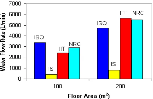
The estimates from the new model were compared with estimates made using the ISO, Iowa State and IIT methods. The latter three methods were chosen as they were considered to be the most valid for residential buildings. Comparisons for houses with floor areas of 100 and 200 m2 are shown in Figure 4.1. Required water flow rates estimated for various fire department intervention times for a house with a floor area of 200 m2 are shown in Figure 4.2.
4.2 Office Buildings
It is assumed that the fire scenario for all of the office buildings is a fast t2 fire. A four-storey office building is chosen, with each storey 3 m high. The room of fire origin is assumed to cover between 25% of the total floor area of one floor of the building. The compartments to which the fire spreads are assumed to be 50% of the total floor area of one floor of the building. The maximum fuel controlled heat release rate was calculated by assuming a heat release rate density of 250 kW/m2 [15]. This was also compared with the maximum ventilation controlled heat release rate, based on the amount of ventilation openings, to ensure that there was sufficient oxygen to support this size of fire.
Figure 4.1 Comparison of required water flow rates estimated using the new model (NRC), and the ISO, Iowa State (IS) and Illinois Institute of Technology (IIT) Methods
Figure 4.2 Comparison of required water flow rate for various fire department intervention times for a house with a total floor area of 200 m2
It is assumed that there are no sprinklers in the office building. The fraction of unprotected openings is assumed to be 0.07, corresponding to the fraction used in the earlier case studies. It is assumed that this fraction is the same on all sides of the office building. Fire is assumed to spread to the adjacent compartments 30 minutes after it begins in the compartment of fire origin. It is assumed that the incident heat flux from the unprotected openings to the neighbouring buildings is equal to 12.5 kW/m2. The heat flux, once all of the exterior walls and roof fails, is assumed to be 300 kW/m2, which is similar to the equivalent heat flux value of 360 kW/m2 used in building codes for a severe hazard. Two exterior walls of the building are assumed to fail in 30 minutes, and the remaining two walls and the roof are assumed to fail in 40 minutes. This is due to the fact that it will take some time for the fire to spread to all of the exterior walls, because of the size of the building. The incident heat flux on the neighbouring buildings is therefore assumed to be 12.5 kW/m2 during the first 30 minutes of the fire and 300 kW/m2 after the fire has been burning for 40 minutes. In between 30 and 40 minutes after the beginning of the fire, the incident heat flux is calculated by dividing 12.5 kW/m2 by the fraction of unprotected openings. The walls on each side of the office building are assumed to be the same size as those of the burning building. As with the residential buildings, the fire department is assumed to begin suppressing the fire 15 minutes after it begins.
The estimates from the new model were compared with estimates made using the ISO and Iowa State methods. The latter two methods were chosen as they were considered to be the most valid for office buildings. The Illinois Institute of Technology method was not used here as it was shown in the earlier case studies that this building is larger than the buildings that it is intended to be used for. Comparisons for office
buildings with floor areas of 500, 1000 and 2000 m2 are shown in Figure 4.3. Required water flow rates estimated for various fire department intervention times for an office building with a floor area of 200 m2 are shown in Figure 4.4.
Figure 4.3 Comparison of required water flow rates estimated using the new model (NRC), and the ISO and Iowa State (IS) Methods
Figure 4.4 Comparison of required water flow rate for various fire department intervention times for an office building with a total floor area of 2000 m2 4.3 Warehouse Buildings
It is assumed that the fire scenario for all of the warehouse buildings is an ultra-fast t2 fire. A single storey warehouse is chosen, with a total height of 10 m. The room of fire origin is assumed to cover between 50% of the total floor area of the
building. The compartments to which the fire spreads are assumed to be 25% of the total floor area of one floor of the building. The maximum fuel controlled heat release rate was calculated by assuming a heat release rate density of 1000 kW/m2. For the
purposes of this calculation, it was assumed that stored material only covers one half of the floor area of the warehouse. Therefore, the maximum fuel controlled heat release for the original fire was calculated by multiplying the heat release rate density by 25% of
the total area of the warehouse. The maximum fuel controlled heat release rate was also compared with the maximum ventilation controlled heat release rate, based on the amount of ventilation openings, to ensure that there was sufficient oxygen to support this size of fire.
It is assumed that no sprinklers operate in the building. The fraction of
unprotected openings is assumed to be 0.16, which is about half of the fraction used in the earlier case studies. It is assumed that this fraction is the same on all sides of the warehouse. Fire is assumed to spread to the adjacent compartments 45 minutes after it begins in the compartment of fire origin. It is assumed that the incident heat flux from the unprotected openings to the neighbouring buildings is equal to 12.5 kW/m2. The heat flux, once all of the exterior walls and roof fails, is assumed to be 300 kW/m2, which is similar to the equivalent heat flux value of 360 kW/m2 used in building codes for a severe hazard. Two exterior walls of the house are assumed to fail in 30 minutes, and the remaining two walls and the roof are assumed to fail in 40 minutes. This is because, as with the office building, it will take some time before all of the exterior walls are attacked by fire. The incident heat flux on the neighbouring buildings is therefore assumed to be 12.5 kW/m2 during the first 30 minutes of the fire and 300 kW/m2 after the fire has been burning for 40 minutes. In between 30 and 40 minutes after the beginning of the fire, the incident heat flux is calculated by dividing 12.5 kW/m2 by the fraction of unprotected openings. The walls on each side of the house are assumed to be the same size as those of the burning building.
As shown in the earlier case studies, there were huge differences in the
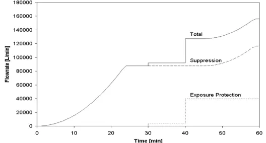
predictions made using existing methods for warehouses. Therefore, estimates from the new model were not compared directly with any of the existing methods. Required water flow rates estimated for various fire department intervention times for a warehouse with a floor area of 2000 m2 are shown in Figure 4.5. These water flow rates are further divided into the amounts required for suppression and exposure.
Figure 4.5 Comparison of required water flow rate for various fire department intervention times for a warehouse with a total floor area of 2000 m2 – total water requirements, and the components for suppression and exposure protection
4.4 Discussion
The predictions made using the NRC model are similar to those made using the ISO and Illinois Institute of Technology methods for the residential buildings in these case studies (Figure 4.1). The predictions made by the NRC and the two existing models are considerably different from those made using the Iowa State method, as the Iowa State method only takes into account the volume of the building, and not any other factors considered by the other methods. As the residential buildings are relatively small, the water requirement estimates made by the Iowa State method will in turn be small.
The NRC model has the advantage of being able to take into account the fire department response time. In the case of the residential buildings, the water
requirements predicted by the NRC model are similar to those predicted using the ISO or Illinois Institute of Technology method, if a typical fire department intervention time in urban centres, 15 minutes, is assumed. However, Figure 4.2 shows that for isolated communities, the required flow rate can increase quickly, as this flow rate is directly proportional to the heat release rate, which is assumed to be directly proportional to the square of the elapsed time in these case studies. On the other hand, a shorter
intervention time will result in a smaller required flow rate. While this concept is well known qualitatively, tools such as the NRC model will allow fire departments to quantify the effects of intervention time on required water flow rate. Areas in which this
information can be used will be discussed in the next section of this report.
The predictions made using the NRC model are similar to those made using the ISO method for the 500 m2 office building, and are similar to those made using the Iowa State method for the 2000 m2 office building (Figure 4.3). The water requirements predictions made by both existing methods are substantially larger than those made using the NRC model for the 3000 m2 office building. This is because the flow rates predicted by the NRC model for a 15-minute fire department intervention time are based completely on the water required for suppression, as no external walls will have failed at this time. Other than the 500 m2 building, at 15 minutes the heat release rate in the compartment of fire origin has not reached its maximum value based on the size of the compartment and the ventilation openings. Therefore, the heat release rates, and hence the water flow rate predictions are the same for both the 2000 and 3000 m2 buildings. On the other hand, the predictions made by the two existing models are dependent on the size of the building, and hence increase as the building floor area increases. For longer fire department response times, after the fire spreads to other compartments and the exterior walls fail, the size of the building will have a larger effect on the predictions made using the NRC model (Figure 4.4). This illustrates how the NRC model is able to take into account features, such as compartmentation and fuel loads, explicitly in its calculations.
As mentioned earlier, there are huge differences in the predictions made using existing methods for warehouses, and therefore, estimates from the new model are not compared directly with any of the existing methods. Figure 4.5 shows how the required water flow rates, which for suppression are directly proportional to the heat release rate calculated for an ultra-fast t2 fire, increase very rapidly for a warehouse. In addition, as the floor areas and ventilation openings in the warehouse are very large, the maximum heat release rates for these buildings, and hence the required water flow rates, will be very large. Depending on the expected intervention time, fire departments may wish to
examine the estimates for the water requirements for suppression and exposure protection separately, and determine whether an offensive attack will be possible using the equipment and personnel available, or whether the department will concentrate on exposure protection. Figure 4.5 also helps to emphasize the importance of detection and suppression systems in warehouses. A detection system that can significantly reduce intervention time and a suppression system that can maintain or reduce the heat release rate of the fire when it is activated will both have a large effect on water requirements for firefighting. Again, while these effects are well known qualitatively, tools such as the NRC model can help to demonstrate these effects quantitatively, as well as assisting in the design of detection and suppression systems.
4.5 Applications of the NRC Model (WTRM)
The results from the NRC model, when combined with information on the equipment and human resources available to a fire department, will allow a number of analyses to be performed. Initial and subsequent responses to individual buildings and/or communities can be planned, based on possible fire scenarios in these buildings and/or communities. The interactive nature of the program is designed to allow planners to perform “what if” calculations when determining their equipment and human resources requirements. Input data, such as information on the building design or the times used to calculate the fire department intervention time, can be changed in order to determine how these changes affect water requirements.
Urban planners could also use the WTRM model for determining the optimal locations of fire stations. Studies could also be performed to determine how mandatory sprinklers in residential buildings affect the locations of fire stations in a community. As a major factor in sizing water mains is providing sufficient water flow rates for firefighting operations, the WTRM model should also be of interest to those designing new water lines or rehabilitating existing water lines. As many water lines are in the need of repair or replacement in the near future, models that can provide information on the required flow rates for firefighting are becoming increasingly important to municipalities around the world.
5. CONCLUSIONS
There are a limited number of existing methods to estimate required flow rates of water for firefighting purposes, and there are large differences between the results predicted by these methods. A new water requirements model developed by the Fire Risk Management Program of the National Research Council of Canada, for use on Canadian DND bases, has been briefly described. This water requirements model is designed to be used in conjunction with submodels from FIERAsystem or as a stand-alone piece of software. Input data from other sources, such as fire test data or heat release rate curves for design fires, can also be used by the water requirements model.
6. REFERENCES
1. Anderson, Gordon C., "ISO Commercial Risk Services," AWWA Seminar
Proceedings - Fire Protection, American Water Works Association, Denver, CO, June, 1986.
2. Linder, Kenneth W., "Water Supply Requirements For Fire Protection," Fire
Protection Handbook, 17th ed., National Fire Protection Association, Quincy, MA, 1981.
3. Royer, Keith, Floyd W. Nelson, "Water For Fire Fighting - Rate-of-Flow Formula,"
Iowa State University Bulletin, Engineering Extension - Bulletin No. 18, Iowa State University, Ames, IA.
4. Buchanan, A.H. (ed.), Fire Engineering Design Guide, Centre for Advanced Engineering, University of Canterbury, New Zealand, 1994.
5. "Fire Protection Water Supply Guideline for Part 3 in the Ontario Building Code", Office of the Fire Marshal Technical Guideline OFM-TG-07-96, Province of Ontario, North York, ON, 1996.
6. NFPA 1231: Standard on Water Supplies for Suburban and Rural Fire Fighting, National Fire Protection Association, Quincy, MA, 1993.
7. Carl, Kenneth J., et al, "Guidelines For Determining Fire-Flow Requirements,"
Journal of the American Water Works Association, May 1973, pp. 335-344.
8. SFPE Handbook of Fire Protection Engineering, National Fire Protection Association, Quincy, MA, 1995.
9. Särdqvist, S., An Engineering Approach to Fire-Fighting Tactics, Report 1014, Department of Fire Safety Engineering, Lund University, Sweden, 1996.
10. National Building Code of Canada 1995, Canadian Commission on Building and Fire Codes, National Research Council of Canada, Ottawa, ON, 1995.
11. McGuire, J.H., “Fire and the Spatial Separation of Buildings”, Fire Technology, Vol. 1, 1965, pp. 278-287.
12. Williams-Leir, G., “Approximations for Spatial Separation,” Fire Technology, Vol. 2, 1966, pp. 136-145.
13. Williams-Leir, G., “Another Approximation for Spatial Separation,” Fire Technology, Vol. 6, 1970, pp. 189-202.
14. NFPA 80A: Recommended Practice for Protection of Buildings from Exterior Fire
Exposures, National Fire Protection Association, Quincy, MA, 1993.
15. NFPA 92B: Guide for Smoke Management Systems in Malls, Atria, and Large