STRUCTURE-FORCE RELATIONSHIP
IN CORTICAL BONE by
PATRICIA CANTY
B.A., Emmanuel C5llege, Boston 1971
SUBMITTED IN PARTIAL FULFILLMENT OF THE REQUIREMENTS FOR THE
DEGREE OF MASTER OF SCIENCE at the MASSACHUSETTS INSTITUTE OF TECHNOLOGY February, 1977 Signature of Author_ Department of Phyics,
-,*February
1, 1977 Certified by_____--- --- ---Thesis Supervisor Accepted by_... Chairman, Departmental CommitteeARCHIVES
2
977
CALCULATION OF THE STRUCTURE-FORCE RELATIONSHIP IN CORTICAL BONE
by
Patricia Canty
Submitted to the Department of Physics on February 1, 1977, in partial fulfillment of the requirements for the degree of
Master of Science
ABSTRACT
To determine a muscle-force to bone geometry cor-relation, forearm (ulna) bone specimens taken from three cadavers were prepared for study. Measure-ments were made of key geometrical and physical parameters. The bone was mathematically modeled as a hollow cylinder beam of variable cross-section and of perfectly elastic material. Structural
analysis of the ulna as a beam under various muscle-force loadings lead tc the derivation of muscle-
force-geometry dependent relationships. The experimental method used is described. The appropriate elastic beam bending theory is discussed and correlation equations are derived. Similarities between the normalized graphs of theoretical predictions and the experimental results are indicative of first order model validity. Results are presented and
sug-gestions for extending the approach adopted are cited.
Thesis Supervisor: Margaret L. A. MacVicar
Table of Contents Page Abstract... List of Figures... List of Tables... Chapter I. Introduction... Chapter II. Background
A. Anatomy of the Arm and Forearm... B. Muscles: Their Structure and
Function... C. Muscles of the Ulna and Radius... D. Biomechanics of the Forearm... Chapter III.
Chapter IV.
Theory
A. Theoretical Framework... B. Mechanical Properties of Bone... C. Application of Theory... Experimental Procedure A. Specimen Characterization... B. Orientation Procedure... C. Sectioning... D. E. F. G. H.
Photographic and Tracing Procedures... Compilation of Data... Data Obtained from the Literature...
Modification of the Model...
Computer Programs... 2 5 8 9 14 19 23 23 40 50 57 65 72 76 79 82 86 95 99
Page
Chapter V.
A. Analysis of Experimentally Obtained
Data... 104
B. Analysis of Theoretically Obtained Data... ... 120
C. Comment...--- -.. --... 138
Chapter VI. Suggestions for Future Work... 140
References... 144
Appendix I. Derivations for Initial Model ... 148
Appendix II. Derivations-Membrane -... 153
Appendix III. Computer Programs- -... 155
List of Figures
Page
Figure 1. Right Humerus, Radius, Ulna
-Anterior View... Figure 2. Bones of the Elbow Region - Detail...
a,c. Anterior View b,d. Posterior View
Figure 3. a. Inferior View of the Radius and Ulna b. Palmar View of the Left Wrist Joint.... Figure 4. Composition of Skeletal Muscle... Figure 5. Origin and Insertions of Muscles of the Rig Upper Extremity - Anterior View... Figure 6. The Left Elbow Joint with Ligaments...
a. Lateral View b. Medial View c. Anterior View
Figure 7. Free Body Diagrams of a Beam in Bending.... Figure 8. Stress and Strain in the Human Femur... Figure 9. Stress-Strain Curves of Wet Long Bones in
Compression... Figure 10. Forces on the Beam-Bone Model... Figure 11. Length Measurements of the Radius and
Ulna... Figure 12. Detailed Views of Prepared Specimen... Figure 13. Construction of the Reference Plane... Figure 14. An Enlargement of Section 332L8...
17 18 20 21 ht 25 33 43 52 56 58 71 73 74 80
Figure 15. A Tracing of the Enlargement in Figure 13-332L8---.- . --- ... -....- . Figure Figure Figure Figure Figure Figure 16. 17. 18. 19. 20. 21. Figure 22. Figure 23. Figure 24. Figure 25. Figure 26. Figure 27. Figure 28. Figure 29. Data Flow Compilation Process... Chart of Data Sources...
Modified Beam-Bone Model...
Flow Chart for DADX... Flow Chart for SHEAR... Centroidal Coordinates (x) vs.
Section Number... Centroidal Coordinates (y) vs.
Section Number... Experimental Cross-Sectional Areas vs. Section Number... Averaged Outer Radii vs.
Section Number... Averaged Inner Radii vs.
Section Number... Averaged Radial Difference vs.
Section Number... The Principal Moments of Inertia, I, 12 vs. Section Number...
Distance to the Outer Fiber, c(x)
vs. Section Number... The Section Moduli-Left vs.
Section Number... Page 81 84 87 92 100 101 105 107 108 110 111 113 114 116 117
Page
Theoretical Cross-Sectional Areas vs.
Section Number...119
Section Moduli-Theoretical Model vs. Section Number...121
Axial Stress vs. Section Number...123
Bending Stress vs. Section Number...124
Total Stress vs. Section Number...125
Figure Figure Figure Figure Figure Figure Section Number... Figure 36. Bending Moment-Membrane vs. Section Number... Figure 37. Shear Stress-Average, Maximum Section Number... Figure 38. Section Moduli-Mb /ab vs. Section Number... Figure 39. Section Moduli-I , Iz vs. Section Number... Figure 40. Cylinder-AA/Ax-Membrane vs. Section Number... Figure 41. Experimental-AA/Ax-Membrane v Section Number... Figure 42. Cylinder - DA/DX - Membrane v Section Number... Figure 43. Experimental -Section Number .. ... .. 127 vs .. . .. . 128 .13 ... 131 ... . 132 ... 133 .13 ... 136 DA/DX - Membrane vs. ... .... .. ... 137 30. 31. 32. 33. 34. 35. Shear Force-Membrane vs. . s
List of Tables Table Table Table Table Table Table I. II. IIIT IV. V. VI. Table VII. Table VIII Table Table Table Table Table Table Table Table IX. X. XI. XII. XIII XIV. A. B. General Terminology... Terminology Specific to Muscles... Arm Muscles... Forearm Muscles - Anterior Group... Forearm Muscles - Posterior Group... Analytical Functions Expressed as Discrete Quantities... Directional Differences in Strengths of Compact Bone... Average Strengths of Ulna, Radius, Humerus
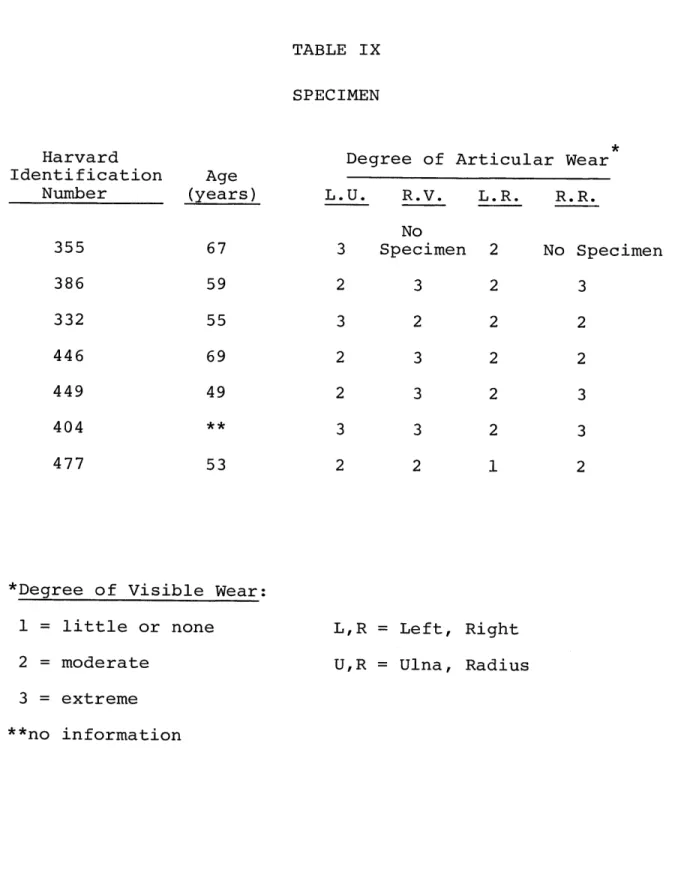
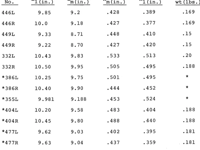
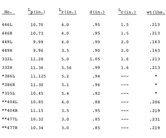
and Femur... Specimen... Radial Measurements... Ulnar Measurements...
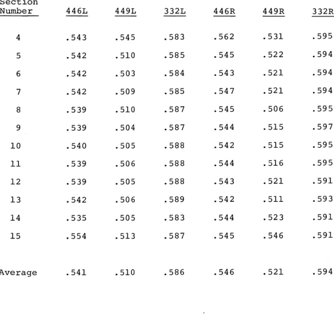
Thickness of Sections...
Referenced Experimental Data on Muscles... Magnitude and Direction of Forces... Variables in DADX Program... Variables in SHEAR Program...
Page 15 24 26 27 29 51 53 55 67 69 70 78 89 93 156 157
9
I. Introduction
Since 1867, the relationship between the form a bone assumes and the bone's function has been the subject of continuing
study. Wolff's Law (1892) is a fundamental statement of this relationship and states that bone structure remodels to reflect the forces acting upon the bone.1 Many researchers have veri-fied this observation qualitatively, among them are Roux,
Pauwels, and Kummer. Roux concluded that the Law of Maximal Economy of Building Material is applicable to bone. This law, which is usually applied to the design of machines, states that a machine is constructed with a minimum of material in order to improve its efficiency in work output by reducing energy loss due to friction and weight.2 The application of
this law to the skeletal system implies that the gross shape (volume distribution of material and cross-sectional area) and the internal structure of bone adapt in order to withstand stresses with a minimum of material.
Pauwels verified Roux's Law by applications in design engi-neering and photoelastic surveys. He found that any building material could be "economized" by two means. The first method
is to diminish stresses in a cross section of the material by changing the position of loading on the material.3 This ap-proach has only theoretical, but no practical value where bone
is concerned. The second method is to distribute the material
such that there is a greater amount available where known bending stresses exist.4
the diameter of the cross section to vary so that the peri-pheral (outer fiber) stresses of the cross section remained a constant, or (2) concentrating material where highest stress
occurred and using no material where no stress was present.5
In applying his two principles to the musculo-skeletal system, Pauwels asserted that bone structure adapts to bending stresses by minimizing the stresses. Although, Roux and Pauwels agreed, in concept, on the functional adaptation of bone to stress, Roux maintained that a axial loading was the only contributor to the process, while Pauwels included the minimization of bending stress in bone as a necessary consideration.6
Kummer correlated x-ray picutres ( via densitometric survey) with stress trajectories obtained from photoelastic studies of
bones. He postulated two levels of bone adaptation to func-tional forces (i.e. forces acting on bone during normal human activities): (1) "absolute minimum construction", defined where the bone adapts its gross shape and inner structure to maintain stress at a minimum value for a given load; and (2)
"relative minimum construction", defined where bone adapts to an actual stress which may not be a minimum for a given load.7 Both types of minimum construction are just restatements of Roux's Law. Kummer also observed that bone's ability to mini-mize its structure but sustain the actual stresses present without fracturing implies a certain safety factor. This
stress to the actual maximum stress under normal conditions.8 When this safety factor is equally large in all parts of a bone, the bone is considered to be of "uniform strength".9
The overall conclusion reached by Roux, Pauwels, and Kummer and supported by extensive photoelastic analysis is that there is a definite correlation between the longitudinal and cross-sectional distributions of bone material and the functional (musculo-skeletal) forces present. The purpose of this thesis is to develop an analytical relationship to express this qualitative observation, thus establishing a criterion for bone remodeling. The central focus of the thesis is the relationship between the cross-sectional area of cortical bone and the local stresses on this area produced by muscular forces. An analytical relationship correlating the structure of bone
to its muscular forces is developed for the ulna. The ulna is singled out for special consideration because it plays a major role in flexion, the most common activity of the forearm, and because relatively few major muscles influence its role in this action.
The force contributions due to various forearm flexor muscles are computer analyzed using a biomechanics program
formulated for the elbow joint.10 It has been shown that the ulna incorporated the y-component of the resultant of the mus-cular forces at the elbow joint. The relative strengths, cross-sectional areas and points of application of the muscles are crucial factors in determining magnitudes of the forces
acting and, consequently, in the degree to which each muscle figures in the stress analysis.
The model used for the ulna is that of a beam in bending and compression:
total axial + abending F/A + M Iy
where
atotal = total stress on a cross section
aaxial = stress on a cross section due to the axial components of the force.
abending = stress on a cross section due to the transverse components of the force. F = axial force
A = cross-sectional area
M = bending moment due to the transverse forces about the neutral axis of the cross section.
y = displacement from the neutral surface (zero stress) to some point on the cross section.
I = moment of inertia of the cross-sectional area about its neutral axis.
The stress and inner and outer radii of the cross section are fixed in order to obtain expressions for the variation of the cross-sectional area of the beam as a function of distance
down the length of the beam. The variations of other structural parameters are also considered (e.g. distance to outer fiber as a function of x, c(x) ). The theoretical approach outlined below was followed:
(a) the initial beam structure chosen so as to be
con-sistent with the minimum material requirement;
(b) the outer fiber stress was taken as constant while
variation in the inner and outer radii about the neutral axis
of the beam was allowed;
(c) the principal stress was then maximized, minimized and
then held constant in order to ascertain what additional
infor-mation could be secured.
The organization of the thesis is as follows: Chapter II
presents physiological background material on bone and muscles
as well as a discussion of the biomechanics of the forearm.
Chapter III is a presentation of theory and development of the
model.
In Chapter IV, a discussion of experimental procedures
and computer programming particularized to this study is given.
Chapters V and VI present the results and data analysis, as
well as suggestions for future work.
A. Anatomy of the Arm and Forearm
An anatomical discussion of the bones comprising the arm and forearm is necessary before considering their bio-mechanical behaviors. A list of relevant terminology used throughout this thesis is compiled and defined in Table I. The skeleton of the forearm consists of two bones, the ulna and the radius. The arm bone is called the humerus.
(Figure 1). In the anterior-superior view (favored by most textbooks), the ulna is located medially with respect to the forearm while the radius is lateral to the forearm. The prox-imal end of the humerus participates in the shoulder articu-lation while its distal end articulates with both the ulna and
radius.
Four key surfaces of the distal humerus should be speci-fically noted. The lateral and medial epicondyles are origin points, respectively, for the long extensor and flexor muscles. The capitulum is the surface with which the head of the radius
articulates, while the trochlea is the surface about which the trochlear notch of the ulna articulates. (Refer to Figure 2).
Proximally, the radius and ulna articulate with each other, the radial notch of the ulna receiving the head of the radius. The ulna is more massive at its proximal end where the ole-cranon (superior-posterior view) forms the point of the elbow. Two major muscle attachments points on the ulna are the
olecra-15 TABLE I GENERAL TERMINOLOGY 12,13 Surface Positions: Anterior Posterior Superior Inferior Palmar
situated
body, on
surface
on the front of the
or nearest the abdominal
situated on the back of the body situated
surface
on the upper or higher
situated on the lower surface
situated
the hand
relative to the palm of
Plane Sections:
Sagittal plane
Midsagittal plane
Frontal plane
Transverse plane
Relative Positions:Medial
Lateral
Proximal
Distalvertical plane passing through the
body from front to back dividing
it into right and left portions
vertical plane at midline, divid-ing the body into right and left halves
vertical plane at right angles to the sagittal plane, dividing the body into anterior and posterior
halves.
horizontal plane at right angles to both the sagittal and frontal planes, dividing the body into upper and lower halves
situated in the middle or nearest to the midsagittal plane
situated on the side or farthest from the midsagittal plane
situated near the point of attach-ment of a bone segattach-ment (near the
center)
situated away from the point of
Table I (continued) Movements: Flexion Extension
Supination
Pronation
Abduction
Adduction
Supplemental Vocabulary:
an articulation
to articulate
palpable
bending to decrease the
mag-nitude of the angle between two
adjacent segments of a body
return from flexion or stretching
out to a greater length
outward (lateral) rotation of
the forearm and hand about the
longitudinal axis of the forearm
so that the palm faces upward
inward (medial) rotation of the
forearm, palm faces downward
sideward movement of a body
segment away from the midsagittal
plane
return from abduction or sideward
movement of a body segment towards
the midsagittal plane
a joint or juncture of two or
more bones
to form a joint
examinable by touch
Right Humerus, Radius, Ulna - Anterior View.14
Radial
-tu berosit
Nut r
ien t
foramen
Head
Greater
tubercle
Del
toid
tuberosity
Lateral
supra
condyl a r
ridge
L acera
\
epicondyle
Capitulum'
t ubercle
na
tomical
"-n
e c
k
"gical
neck
Styloid
process
CTrochlear
notch
Coronoid
process
-Nutrient
foramen
In terosseous
-
bo r
de r
.Head
Styloid
process
Right
radius and Ulna
-Intertubercular
sulcus (bicipital
groove)
Medial
supracondylar
r idge
Coronoid
fossa
Medial
epicondyle
hT
rochlea
Right humerus
Figure 2. Bones of the Elbow Region - Detail15,16
a,c. Anterior View b,d. Posterior View
Radial fossa
Lat.
for
Capitu lum
-Trochlea Notch
Radial
Notch-Neck
Tuberosity:
for
fbursa
L Biceps
Anterior
oblique
line
ANTERIOR
VIEW
Medial
supracondylar
ridge-Med.
epicondyle:
for flexor s
for Ulder
nerve
-Surface for
Olecranon bursa
Supinator crest
Posterior
border
Coronoid
fossa
Med.
epicondyle
for flexors
T rochlea
Olecranon
a
Tubercle on
-Ycoronoid prod.
Tuberosity
for Brachialis
Supinator
fossa
(b)
(d)
POSTERIOR
V I
EW
Lateral
supracondylar
ridge
)lecranon fossa
Lat. epicondyle:
subcutan area
f
or Exten sors
for Anconeus
-Trochlea
Head
Neck
-Tube rosi
t
y
Posterior
oblique line
(a)
(c)
non and the coronoid process. Distally, the shaft of the ulna, the lateral border of which is known as the interos-seous crest, becomes less massive as one approaches the ulnar head. (See Figure 1). The radial shaft progresses from the head into a neck, below which the radial tuberosity protudes medially. The interosseous border begins below the tuberosity, separating into anterior and posterior ridges. Distally, the radius broadens bilaterally for its articulation with the
scaphoid and lunate bones of the hand. The styloid processes of both the ulna and radius are easily palpable at the wrist. Figure 3 shows the inferior view of the radius and ulna as well as a palmar view of the left wrist joint. More will be
said about the manner of articulation of the humerus, ulna and radius in section IID.
B. Muscles: Their Structure and Function
Before initiating a study of the stresses in a bone, a knowledge of the basic structure of muscles and the mechanics of muscle behavior is essential to understanding the role of muscles as forces.
A skeletal muscle consists of thousands of long, slender fibers, each 10-100y in diameter, running parallel to each other and surrounded by connective tissue endomysium. (See Figure 4). Myofibrils, sarcoplasm and sarcolemma are the main constituents of the fiber. Myofibrils, .5-lp in diameter, are arranged in columns with from several hundred to several
Figure 3. a. Inferior View of the Radius and Ulna b. Palmar View of the Left Wrist Joint
Styloid
process
Receives
1
~
Receives
scaphoid bone
lunate bone
Attachment of
ligament to
disk
Syloid
process
(a)
Interosseous membrane
Ulna
Palmar u
ligament
Ulnar collateral
ligament
Pisifo
Triangular
ar radioulnar
ligament
Imar radiocarpal
ligament
1dial
collateral ligament
Scaphold
Capitate
Figure 4.
18 Composition of Skeletal Muscle
a. Cross Section of Muscle
b. Organization of Muscle Tissue c. A Muscle Fiber
Fibril
Column of
fibri IS
Fiber
b6,
Fasciculus
Myof ibrils
Nucleus
Sarcolemma
Sarcoplasm
(a)
Nuclei
..
e
Sarcolemma
Miss'*(b)
(c)
thousand in each muscle fiber. The sarcoplasm is the fluid thorugh which the contractile muscle fiber moves. The sarco-lemma, a membrane surrounding the myofibrils and sarcoplasm, conducts the action potential, which is generated during a muscle contraction, throughout the fiber.
All of the muscle fibers of the intact muscle do not contract in a smooth continuous shortening, but by means of many rapid changes. Thus the apparently smooth contraction observed in muscles is actually a summation of all the rapid changes of the fibers. The nerve and chemical considerations in muscles contraction are beyond the scope of this thesis.
The fiber arrangement of a given muscle determine the performance character of the muscle. Muscle contraction is a shortening of the length of the fibers to produce tension. Thus the fiber arrangement is of importance in considering the magnitude of a muscle's contraction and its ability to exert a force. The two main arrangements are called fusiform and penniform. The fusiform muscle has a longitudinal distri-bution of fibers, running parallel to each other and enabling maximum range of movement of a body segment during contraction. An example of this is the shunt muscle which acts chiefly
during rapid movements and acts along the long axis of a bone segment to provide centripetal force helping to stabilize the joint. 9 The penniform (feather-like) arrangement is a diagonal
alignment of short muscle fibers which approach the muscle tendon obliquely from one or more sides, producing a greater force than the fusiform muscles over a shorter range of move-ment. An example of the "penniform arrangement, the spurt muscle, provides acceleration along the direction of motion
20
of the bone segment about a joint. Various muscle functions and terms are listed and explained in Table II.
The amount of tension a muscle can develop during maximal contraction depends upon the number and size of the muscle
fibers as well as their internal fiber arrangement. It has been found that the total force which a muscle can exert is directly proportional to the total cross-sectional area of the muscle at its widest point, including all the muscle's fibers. Since the penniform arrangement has a greater number of fibers within a cross-sectional area, the force of such a muscle will be greater than that of the fusiform type.
C. Muscles of the Ulna and Radius
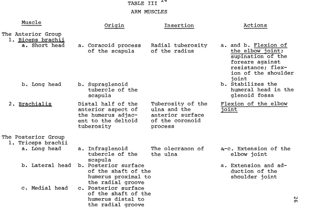
Figure 5 shows the location of the origin and insertion points of those muscles acting on the arm and forearm about the elbow and wrist. Tables III, IV and V give the names, origins, insertions and functions of these muscles.
D. Biomechanics of the Forearm
(1) The ability to flex, extend abduct or adduct the
articu-TABLE II 21,22
TERMINOLOGY SPECIFIC TO MUSCLES
Origin
Insertion
Agonistic muscle Antagonistic muscle Shunt muscle Spurt musclethe attachment end of a muscle on the more stable or stationary bond segment
(usually more proximally located in body)
the attachment end of a muscle on the more easily moved bone segment (usually more distally located in body)
directly responsible for effecting a particular movement or activity (may be capable of more than one activity)
causes the opposite movement from that of the agonistic muscle, thus contri-buting to the smoothness of the action
it's origin is situated close to the joint crossed while the insertion is a greater distance away (joint stabiliz-ing function)
it's origin is situated further away from the joint crossed than the
in-sertion (provides increased motion about a joint)
Figure 5. Origin and Insertions of Muscles of the Right 23 Upper Extremity - Anterior View
biceps(short head)
-supraspinatus
subscapularis
-lat.
dorsi----teres
maj.-pectoralis
maj.--deltoid
b r ac
hio
r
adialis
ext. carpi
radialis long.
superficial
extensor
s
biceps brachii
supinator
flex. digit.
superf icialis
flex. pollicis long.
bra chiorad ial
.
abd. poll. brev.
flex. poll. brev.
opponens
poll.
abd. poll. long.
adductcr poll.
flex. poll.
brev.
abd. poll.
brev.
flex. pol. long.'
palmar interossei
_
flex.
digit.
superficiali
serratus ant.
subscapularis
triceps(iong head)
coracobrachialis
brachialis
pronator teres
superficial flexors
brachialis
flex.
digit.
superficialis
-flex. digitorum profundus
__-,pronator
quad.
flexor carpi uln
abductor digit. min.
opponons digit. min.
flexor carpi uln.
opponens digit min.
adductor pollicis
(obi. & trans. heads)
abd. digit. min.
f lex.
flex. brev.
digit.
profundus
S
INSERTIONS-STIPPLED
OR IGINS -SOLID
TABLE III 24 ARM MUSCLES
Insertion
The Anterior Group
1. Biceps brachii
a. Short head
b. Long head
2. Brachialis
The Posterior Group
1. Triceps brachii a. Long head b. Lateral head c. Medial head
a. Coracoid process
of the scapula b. Supraglenoid tubercle of the scapulaDistal half of the
anterior aspect of the humerus adjac-ent to the deltoid tuberosity
a. Infraglenoid tubercle of the scapula
b. Posterior surface
of the shaft of the humerus proximal tc the radial groove c. Posterior surface
of the shaft of the humerus distal to the radial groove
Radial tuberosity of the radius
Tuberosity of the ulna and the
anterior surface of the coronoid process The olecranon of the ulna a. and b. Flexion of the elbow joint; supination of the foreare against resistance; flex-ion of the shoulder
joint
b. Stabilizes the
humeral head in the glenoid fossa
Flexion of the elbow
joint
a.-c. Extension of the
elbow joint
a. Extension and ad-duction of the shoulder joint
a,'
Muscle
Origin
Insertion
A. Superficial Anterior Group 1. Brachioradialis 2. Pronator tereg a. Humeral head b. Ulnar head 3. Flexor carpi radialis 4. Palmaris longus
Proximal two thirds of the lateral supra-condylar ridge of the humerus
a. Medial epicondyle of the humerus
b. Medial side of the
coronoid process of the ulna Medial epicondyle of the humerus Medial epicondyle of the humerus
5. Flexor carpi
ulnaris
a. Humeral head a. Medial epicondyle
of the humerus
b. Ulnar head
Styloid process of the radius Middle of the lateral surface of the shaft of the radius Bases of the 2nd and 3rd metacar-pals Central part of the flexor re-tinaculum and palmaraponeuro-sis
The pisiform, ham-ate, and base of the 5th metacarpal
b. Medial margin of
the olecranon of
the ulna
Flexion of the elbow
joint
Assists in elbow flexion against re-sistance; pronation
of the forearm
Flexion of the wrist joint; assists in radial flexion of the wrist joint
Assists in flexion of the wrist joint
Flexion of the wrist
joint; assists in
ulnar flexion of the
wrist joint
Muscle
ActionsMuscle 6. Flexor digitorum superficialis a. Humeral head b. Ulnar head c. Radial head Origin
a. Medial epicondyle
of the humerus
b. Medial side of the
coronoid process
of the ulna
c. Oblique line of
the radius
Insertion
ActionsSides of the Assists in flexion
shafts of the 2nd of the wrist joint;
phalanges of the flexion of the MP
four fingers and proximal IP
joints of the four
fingers
B. Deep Anterior Group
1. Flexor digitor-ium profundus 2. Flexor pollicis longus 3. Pronator quad-ratus
Proximal three fourths of the palmar and
medial surfaces of the shaft of the ulna
Palmar surface of the shaft of the radius
Distal fourth of the palmar surface of the ulna Bases of the distal phalanges of the four fingers Base of the distal phalanx of the thumb Distal fourth of the palmar sur-face of the radius
May assist in
flex-ion of the wrist
joint; flexion of
the MP and IP joints
of the four fingers May assist in flex-ion of the wrist
joint; flexion of the
MP, proximal, and distal IP joints of the thumb; assists in adduction of the
thumb
Pronation of the
fore-arm
Origin
Insertion
C. Superficial Posterior Group
1. Anconeus Posterior surface of
lateral epicondyle of the humerus 2. Extensor carpi radialis longus 3. Extensor carpi radialis brevis 4. Extensor digit-orum 5. Extensor digiti minimi 6. Extensor carpi ulnaris
Distal third of the lateral supracondy-lar ridge of the humerus Lateral epicondyle of the humerus Lateral epicondyle of the humerus Lateral epicondyle
by the common extensor
tendon
Lateral epicondyle of the humerus by the common extensor tendon
Lateral side of
the olecranon of
the ulna and
proximal fourth
of the shaft of
the ulna
Base of the 2nd
metacarpal
Base of the 3rd
metacarpal
Dorsal surface of
the bases of the
2nd phalanges and
dorsal expansions
of the four
fin-gers
The extensor
ex-pansion and tendon
of the extensor
digitorum at the
proximal phalanx
of the little
finger
Ulnar side of the
base of the 5th
metacarpal
Extension of the elbow joint Assists in extensionand hyperextention of
the wrist joing; radial
flexion of the wrist
joint
Extension,
hyperexten-sion, and radial
flex-ion of the wrist joint
Extension and
hyper-tension of the wrist
joint and MP joints of
the four fingers;
ex-tension of the IP
joints of the four
fingers
Assists in extension of
the wrist joint;
exten-sion any hyperextenexten-sion
of the MP joint of the
little finger; extension
of the IP joints of the
little finger
Extension,
hyperexten-sion, and ulnar flexion
of the wrist joint
Muscle
ActionsOrigin
Insertion
D. Deep Posterior Group
1. Supinator 2. Abductor pollicis longus 3. Extensor pol-licis brevis 4. Extensor pol-licis longus 5. Extensor indicis Lateral epicondyle of the humerus and adjacent area of the ulna and joint ligaments
Lateral part of the
dorsal surface of
the shaft of the
ulna
Dorsal surface of the shaft of the radius
Lateral part of the middle third of the dorsal surface of the shaft of the ulna
Dorsal surface of the shaft of the ulna
Lateral surface
of the proximal
third of the
radius
Radial side of
the base of the
first metacarpal
Base of the first
phalanx of the
thumb
Base of the distal
phalanx of the
thumb
The tendon of the
extensor digitorum
to the little
finger
Supination of the
forearm
Assists in flexion and
radial flexion of the
wrist joint; abduction
of the CM joint of the
thumb
Assists in radial
flexion of the wrist
joint; extension of
the CM and MP joints
of the thumb
Assists in extension
and hyperextension of
the wrist joint;
exten-sion and adduction of
the CM joint of the
thumb; extension of the
MP
and
IP
joints of the
thumb
Assists in extension and
hyperextension of the
wrist joint; extension,
hyperextension, and
ad-duction of the MP joint
of the index finger;
extension of the
IP
joints of the index
fin-ger
lation of the humerus, ulna and radius about the elbow (and to a lesser extent, the wrist).
(2) The elbow joint has two degrees of freedom of motion and is called a throchginglymus; that is, it has hinge motion
27
in one plane and axial rotation in another. The trochlea (humerus), which articulates with the trochlea notch of the ulna, is a hyperboloid. (Refer to Figure 2). Its surface has two curvatures: concave in the frontal plane and convex
in the sagittal plane. (Sagitally, it forms almost a complete circle except at the medial edge where the curvature is almost helical). According to Steindler 28 only about 3300 of the trochlea is covered with cartilage since the anterior and posterior surfaces are separated by a bony wall--the distal shaft of the humerus and the olecranon fossa. The trochlear notch, which is semicircular in curvature, has a vertical ridge which fits into the neck of the trochlea; the notch is bordered proximally the olecranon and distally by the coronoid process
(Figure 2) forming an almost perfect fit. Its angular range of motion 1900, is limited by the olecranon fossa. This joint, the humero-ulnar articulation, forms the hinge motion of the elbow.
(3) The capitulum (humerus) is convex both frontally and sagitally forming half a sphere, although the radius of this
sphere is not quite constant. The capitulum also faces forward and downward and is covered with cartilage, indicating a 180 of angular involvement in articulation. The head of the radius
is indented slightly to receive the capitulum and has its thickest covering of cartilage in the middle of the indent.
0
The slight cavity has an angular value of about 40 . This junction, the humeroradial articulation, contributes to the pivot motion of the elbow joint.
(4) The total angular range of motion of the forearm about the elbow is 140 , consistent with the allowed range of motion of each articulation. Although a wide range of movement is possible, the radial and ulnar collateral ligament (Figure 6) attach laterally and medially to the bones blending into the annular ligament which encircles the head of the radius. These ligaments provide added stability to the elbow joint.
(5) The radioulnar articulation (pivot motion) consists of three distinct joints. The proximal radioulnar joint at the elbow is comprised of the head of the radius which is
re-strained to articulate with the radial notch of the ulnar by the annular ligament. This restraint stabilizes against lateral and distal displacements of the radial head while allowing pivotal motion of the head to occur within the ring of the
ligament. The distal radioulnar joint, where the ulnar notch of the radius articulates with the ulnar head, complements the proximal joint allowing axial rotation. The middle radioulnar
joint is maintained by the interosseous membrane which runs distally and medially from the radius to the ulna. The fiber
arrangement maintains a maximum spatial distance between the two bones during supination while simultaneously restraining
Figure 6. The Left Elbow Joint with Ligaments2 9 a. Lateral View
b. Medial View
Annular
ligament
/Humerus
Radius
- -Olecranon
.
Ulna
Radial collateral
ligament
(a)
Obliqi
cord
-Ulna
Annular
ligament
Radius
Interosseous
membrane
(C
)
Annular ligament
-- Rad ius
Olecranon
-%
Ulin a
(b)
the radial head from movements upward against the capitulum. (Figure 6).
(6) The humeroulnar and humeroradial articulations allow for flexion and extension of the forearm with small amounts of abduction and adduction. Maximum flexion (1400-1450 depend-ing on researchers) is limited by muscle tissue between the arm and forearm, while maximum extension is limited by those muscles crossing the anterior view of the elbow joint.
Hyper-o
o30
extension can occur to about 10 -20 . The radial head, bound closely to the ulna, glides along the proximal surface of the capitulum during flexion-extension. The radioulnar articula-tions allow for supinated and pronation of the forearm, the radius pivoting about the ulna.
As mentioned in Chapter II, distally the scaphoid, lunate and triangular bones of the hand articulate with the triangular articular disk located distal to the ulna, but connecting with the distal radius. The wrist joint is known as the radiocarpal articulation. It is a very stable joint due to the number of ligaments and muscle tendons which pass over it. (Figure 3b). The wrist is an example of an ellip-soid joint, its two degrees of freedom allowing flexion-extension, hyperflexion-extension, radial and ulnar flexions and
circumduction. There is no active rotation, although the hand can be passively rotated via the forearm.
The degree of articulation of the forearm about the elbow joint is dependent upon the muscle activity. This
ac-tivity consists of three phases in an excitation-contraction
coupling:
the latent phase, the contractile phase, and the
relaxation phase. The explicit contractile phase is of
interest in this work.
An unstretched muscle is considered to be at its rest
length. The force due to a muscle contraction is directed
along the center line of action of the muscle, usually
desig-nated by the direction of the tendon attachment of the muscle
on the bone. When a muscle contracts under conditions where
little or no shortening occurs, i.e. there is no decrease in
length relative to the initial length, this is called
iso-metric contraction. The muscle fibers maintain the same length
during contraction, but there is a marked increase in tension
in order to counterbalance an external load. No external work
is done, but the internal energy produced by the muscle is
converted into heat. Examples of an isometric contraction are
holding a weight or pressing a wall.
A situation where the muscle fibers maintain a constant
tension by changing their length is called isotonic contraction.
Shortening of the muscle occurs, thus producing work. An
example of isotonic contraction is moving a weight over a
certain distance. Pure isotonic contraction is rarely found
outside the laboratory. Normal movements require muscle
tensions to vary, combining both isometric and isotonic
contractions.
are dependent on the magnitude of the loads moved. The heavier the load, the less the total shortening. In the limit of no shortening, the state of isometric tension is reached. The velocity of shortening follows the same inverse relationship. Hill31 and Wilkie32 established an analytical relationship
between the muscular force and its velocity of shortening, i.e.
(P+a) (V+b) = constant = Po (a+b)
where
P = Force of contraction V = Velocity of contraction
Po = Force at V=0, isometric contraction a,b = Constants .
Pertuzon and Bouisset 3 showed that the relationship between a muscle's instantaneous force and its associated velocity of
shortening is about the same as the relationship established between maximal values of the force and concurrent velocity.
The literature contains many studies which attempt to determine and/or verify force relationships between various muscle activities and anatomical characteristics. The author
found that it is generally difficult to correlate the data due to the variation in initial experimental conditions,
however certain generalized observations can be made and sub-stantiated:
1. a definite linear relationship exists between the
absolute force, or strength of a muscle, and its effective
cross-sectional area;
2. the flexor muscle is stronger than the extensor;
and,
3. the muscular force has an angular dependency about
a joint.
The absolute force of a muscle is defined as the maximum
contractile force during voluntary isometric contraction due
to 1 cm
2of effective cross-sectional area of muscle.34 The
effective cross-sectional area is the area of a section
perpendicular to all the fibers of a muscle. For the long,
parallel fibers of the fusiform muscle, the effective area is
equal to the physiological area; for a penniform muscle, there
is a greater number of fibers per cm
2in its physiological
cross-sectional area, and this area may be at an oblique angle
to the anatomical cross-sectional area. This difference may
account for discrepancies in calculations found in the
literature.
Fick (1903) calculated the strength/cm
2of flexor muscles
about the elbow to be 6-10 kg/cm2.35,36 Morris,37 calculation
(1948) yielded 9.15 kg/cm
2for the flexors of males and
7.5 kg/cm
2for those of females, consistent with Fick's
result. On the other hand, Rechlinghausen (1920) obtained
3.6 kg/cm
2,38 and Ikai and Fukunaga39 (1968) got 4.7 kg/cm2,
the latter value being independent of sex and age. Going a
step further, deDuca 0 found that the physiological cross-sectional areas of the anterior fibers versus the posterior fibers of the deltoid muscle (penniform) were inversely pro-portional to each other. This result suggests not only an explanation for the opposing physical function of these two groups of fibers, but also a clear understanding of how the discrepancies, noted above, in strengths of muscles during specific activities could occur.
In considering the relative strength between flexors and extensors, Steindler41 states that the flexors are one and a half times stronger than the extensors, a result confirmed by Singh and Karpovich.4 2
The angular dependence of the muscle force was established by Wilkie.43 Jorgensen and Bankov calculated the maximum isometric torque due to all the elbow flexors and determined its dependence on the elbow angles and on the position of the forearm relative to the humerus. This relationship was con-firmed by Singh and Karpovich.45 Wilkie also established the lever ratio, which is constant throughout flexion but varies
from muscle to muscle. The lever ratio is defined as the ratio of the moment arm of a muscle about the elbow joint to the moment arm of the resistance force, which is at the hand.
Tables IV and V list all the muscles of the arm and forearm. Of those muscles, five participate in some way in flexion about the elbow joint. They are: brachialis, bicep brachii, brachioradialis, pronator teres, and extensor carpi
radialis longus. The last two muscles are pronator-supinator muscles with minor flexion activity. The first three muscles are considered to be the major flexors of the elbow joint. Many researchers list the biceps brachii as the principal
flexor,46,47 not the brachialis muscle.4 8,4 9 Yet, electro-myography (EMG), a technique considered to be the most
accurate indicator of which muscles are actively participating in specific movements, shows that the brachialis is the
superior flexor under all conditions.5 0 The biceps brachii is a strong flexor only when a load is present and the forearm is supinated. The brachioradialis acts as a shunt muscle,
supplying a quick force along the long axis of the bone for powerful movements. It functions as a reserve force.
Steindler51 lists the brachialis and biceps brachii (both penniform muscles) as the principal flexors and the
brachioradialis and extensor carpi radialis longus (both
fusiform muscles) as auxillary muscles. Kelley52 and Wilkie5 3 include the pronator teres as an auxillary flexor when a load is present, while Basmajian54 states merely that there is no activity in the pronator teres if there is no load or only a minimal load.
The analytical basis for the prediction of the mechanical response of bone to forces arising from isometric muscle
contractions has been extracted from beam bending theory as applied to perfectly elastic media. This development is
presented in IIIA. Referenced data, in which the actual mech-anical properties of bone are presented, appears in IIIB. Al-though the anisotropy of bone is evident, the linearity of the stress-strain relation within specified limits is shown. Applicability of the material model of bone as perfectly
elastic is thus upheld. Finally section IIIC develops the application of beam bending theory to the ulna. (In Chapter IV, the beam loading is modified to more accurately model the actual muscle forces present.)
A. Theoretical Framework 5 5 ,5 6
In machine design, one is concerned with the relationship between external forces acting on a structural member, and internal forces and deformation resulting from the external forces. The investigation of this relationship usually begins with the following assumptions concerning material properties:
1. perfect elasticity -- upon the removal of loads, the material completely returns to its original shape;
2. structural and compositional homogeneity;
3. isotropy -- mechanical properties are directionally
41
4. linearity -- stress and strain are linearly related
in accordance with Hooke's Law;
5. elastic properties -- the mechanical response to either
tension or compression is the same.
For an elastic body stressed in one direction,
a
= F/A
=
EE
(3.1)
or, the stress, a, is equal to the force (F) per unit area (A)
and is also linearly proportional to the strain c by Young's.
Modulus, E. In general,
a
, a and a are stresses due to
x
y
z
forces acting on surfaces, the normals of which are,
respect-ively, in the x, y and z directions. 6 ,
C y
and
ez
are the
strains or increments of deformation per unit length of the
beam associated with the respective normal stresses.
The
resultant strains due to a, ay, a are:
-a
V (a
7--~
1C
x E x y z = -[a -v (a+a
+)
] (3.2) y E y x zz
E
z
xywhere v =
Poisson's ratio, the ratio of the transverse unit
strain to the longitudinal unit strain.
A cantilever beam in bending is a horizontal beam fixed
at one end and loaded either by vertical point forces or
distributed loads along its length and/or by force couples at
its free end. The simplest case is a single force acting at
the free end. In order to calculate the internal stresses in
the beam resulting from bending, the shear force, V, and
bending moment, Mb, acting at various cross sections of the
beam must be determined. The vertical shear force at a
trans-verse section of the beam is equal to the resultant of the
external forces that lie on either side of the section. In
Figure 7, the beam in (a) has been cut, at transverse section
mn, into arbitrary portions (b) and (c), the resulting free
bodies.
The bending moment at a section is the algebraic sum of
the moments due to the applied loads and reactions which lie
on either side of the action. The bending moment is related
to the shear force and the applied load by the expressions:
dMb
d -V(x) (3.3)
and
dV
w
(3.4)
where w =
intensity of a continuous load distributed along the
beam.
57 Free Body Diagrams of a Beam in Bending
I
I
I I
I I
*1 I
I I
I
I
I I
I I
X~NX~V
The two types of stresses resulting from bending of a
beam, shear stress and bending stress, will be discussed
separately. The following assumptions are used in developing
the theory for a beam under pure bending and having a
longi-tudinal plane of symmetry:
1. the beam is straight and of uniform planar cross
section;
2. the cross section remains planar and normal to the
longitudinal fibers* of the beam after bending;
3. the resultant of the applied loads lies in the
longitudinal plane of symmetry; and
4. the material structural and compositional properties
of the beam are homogeneous along the beam's length and are
symmetrical with respect to the plane of loading. The
con-ditions are imposed only to establish a deformation pattern
where bending (rather than buckling) is the primary mode of
failure.
Application of these assumptions leads to determination
of the neutral surface, i.e. that surface on which the
fibers do not undergo any strain during bending. The
inter-section of the neutral surface with any cross inter-section is
*
The beam is ima
gined to be composed of thin longitudinal
rods or fibers. 58
called the neutral axis. The radius of curvature (p) of the beam is given by
1 _d4 A4
p ds As
where A$ is the change in slope angle of a curve and As is the distance along the curve, and the unit elongation of any fiber is
E = -.
(3.5)
x p
The longitudinal strain is proportional to the distance y from the neutral surface to a given fiber and inversely proportional to the radius of curvature.
From conditions of moment and force equilibrium over a beam cross section, the following equations for a symmetric
beam are presented without providing the detailed calculations.59
EF = a dA 0 (3.6)
x fA' x
EM = za ,dA 0 (3.7)
EMz -fAy xdA = Mb (3.8)
Application of the conditions of stress and deformation (Equations (3.1), (3.2) and (3.5)
)
to the above equations yields:Iz A y2dA (3.9)
and
r = -(3.10)by x I z
where Iz, the moment of the beam cross section is obtained with respect to the neutral axis. The moment of intertia
about an axis is the measure of a section's resistance to bending about that axis. a is the stress distribution along
the beam length due to bending, expressed in terms of Iz and the bending moment. Further, ax depends on y, which is the distance from the neutral surface to any point on the cross section. Maximum stresses (tensile and compressive) occurring in the outermost fibers are given by
Mbc
a = - M (3.11)
MAX I
z
where c is the distance to the outer fiber from the neutral axis. The quantity Iz /c, denoted by Z, is called the section modulus; it is a measure of the bending stress induced in the member due to a bending moment.
The combination of EF = 0 with the curvature expression (3.5) yields
fAydA
=0,
(3.12)which is the first moment of the area with respect to the neutral axis. This implies that the neutral axis must pass through the centroid of the cross-sectional area. The co-ordinates of the centroid are defined by:
-
fxdA
and dA . (3.13)of the cross section; it generally does not include the
centroidal axis.
Although it was derived for the case of constant bending,
Equation (3.10) is generally assumed to be valid for a bending
moment that varies along the length of the beam, i.e. when a
shear force is present. The vertical (or longitudinal) shear
stress is given by:
T
VQ
and Q=j ydA, (3.14)xy
Izt
A1
where
Tis the shear stress on the x face of the beam in the
xy
y-direction; V is the shear force producing that stress; Al
is the portion of the area above the layer on which the shear
stress acts; Q is the first moment of the area, A
1,
about the
neutral axis; and t is the width of the cross section at the
plane on which the shearing takes place.
For a material in the xy-plane subject to a
two-dimension-al stress system, the equilibrium requirements of E
=
0 at a
point leads to the differential equations:
X +
y
+ = 0 (3.14)3r y y -315
y+ + y = 0 (.5
y
x
where x and
y
are body forces distributed over the cross
section.
The principal stresses (the maximum and minimum value of the tensile or compressive stresses) and the maximum shear stress are determined by mathematical analysis of the forces acting on an element of the material or by construction of Mohr's circle. The principal stresses due to a , a and T
are:
a +a
Fa
-a
/
(
.
)
+ 2 . (3.16)12 2 2 x
They occur on planes defined by: 2T
tan 2# = x (3.17)
±(a -a)
x y
The maximum shear stress occurs on a plane 450 from the principal stress and is defined as:
a o2 1/2
T max ( ) + 2 .y] (3.18)
For a beam of variable cross section, Equations (3.10) and (3.14) can still be applied. The error is small* if the elastic axis is assumed to be the line of centroids and if the
cross sections are taken to be perpendicular to that line. If there is no axis of symmetry in a section, then the
location of the principal centroidal axis must be determined
*
Boley calculates the error to be of the order of (hm/L)2, where h is the maximum height of the beam and L is its
60-to calculate stresses correctly.
(The principal axes of
inertia are axes about which the moment of inertia of any cross section is a maximum or minimum.) The product of inertia is used to calculate the principal axes of asym-metrical sections. For moments of inertia given by:I =
fA
y2dA ,I = fAX2dA, and I = fAxydA (3.19)from transformation equations, the angle for which the new moment, I, is a maximum or minimum is given by:
21
tan 2
-
. (3.20)y x
One then obtains the principal moments I , I
1 2
I = Y) (1 -y +I 1/2
(3
.21 )
i
2
_ 2 xy2
The parallel axis theorem enables one to calculate the moment of inertia with respect to any arbitrary axis which is
parallel to an axis passing through the centroid of the area for which the moment of inertia is known. Restated:
I' = f + Ad2
, (3.22)
x
x
where
Y = moment of inertia about the centroid x
I' = moment of inertia with respect to an arbitrary parallel x' axis
d = distance between the axes A = area of the cross section
If the cross sections are irregular in shape, integration
is not possible and graphical analysis must be performed.
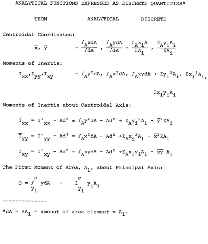
Table VI lists the discrete representations of the analytical
expressions which were used in this thesis.
B. Mechanical Properties of Bone
The results of work by Yamada61 and published in a
compilation of mechanical properties of bone by Evans62 show
that for strains less than .004, the assumption of perfect
elasticity is reasonable for this study.
(See Figure 8).
Presented next is a summary of research done by these and
other investigators64 on machined samples of cortical bone
(compact bone).
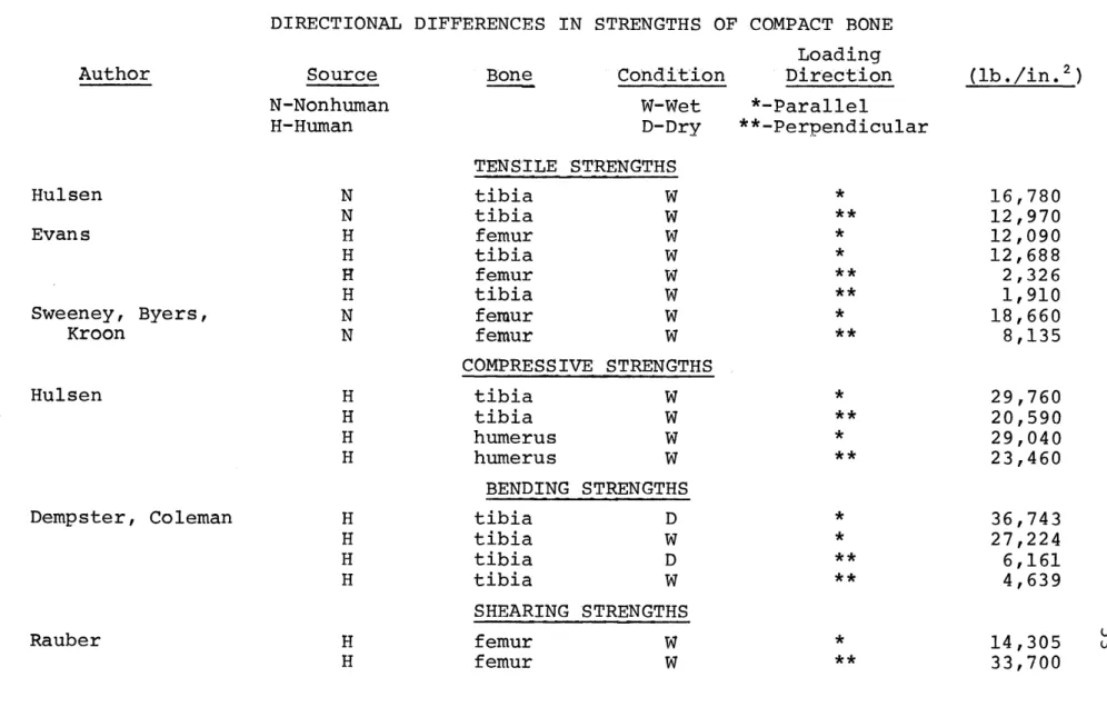
The tensile strength of dry bone has been found to vary
from 7000 lb./in
2to 40,000 lb./in
2depending on the direction
of loading, speed of load and geometry of the specimen
(cubical vs. planar).
The tensile strength of dry bone is
less than its
compressive strength (in some cases by as much
as 1/2).
The effect of drying on fresh or embalmed bones
is to increase the tensile and compressive characteristics
of the samples as well as the modulus of elasticity. As
might be expected, strengths also vary in-magnitude with the
direction of testing (i.e., parallel or perpendicular to the
long axis of the bone), thus exhibiting the anisotropic
pro-perty of bone.
(Most mechanical properties are greater in
magnitude when tested parallel to the long axis.)
Table VII
TABLE VI
ANALYTICAL FUNCTIONS EXPRESSED AS DISCRETE QUANTITIES*
TERM ANALYTICAL DISCRETE
Centroidal Coordinates: xf y / AxdA /dA fA ydA fdA A 1 AyiAi EA. ' EA. 1 1 Moments of Inertia:
I xx yy xy,I ,I = f y2dA fA x2dA, fA xydA + Eyi2A., Ex.2 A. Ex.y.A.
i111
Moments of Inertia about Centroidal Axis:
I
= I' - Ad 2 = f y2dA - Ad2 + E y, 2 A. - y2EA. xx xx A Al 1 1 I = I' - Ad2 fAx2dA - Ad2 _EA 2A. - x2 EA. -f x= I' - Ad2 = f AxydA - Ad 2 iE xyiAI - xy A.The First Moment of Area, A,, about Principal Axis:
C
Q=
f
ydA
y1 c + y.A. 1 1 y1Stress and Strain in the Human Femur 6 3
S
0 N .004 NCs 010 Pef GNOM