Publisher’s version / Version de l'éditeur:
Vous avez des questions? Nous pouvons vous aider. Pour communiquer directement avec un auteur, consultez la
première page de la revue dans laquelle son article a été publié afin de trouver ses coordonnées. Si vous n’arrivez pas à les repérer, communiquez avec nous à PublicationsArchive-ArchivesPublications@nrc-cnrc.gc.ca.
Questions? Contact the NRC Publications Archive team at
PublicationsArchive-ArchivesPublications@nrc-cnrc.gc.ca. If you wish to email the authors directly, please see the first page of the publication for their contact information.
https://publications-cnrc.canada.ca/fra/droits
L’accès à ce site Web et l’utilisation de son contenu sont assujettis aux conditions présentées dans le site LISEZ CES CONDITIONS ATTENTIVEMENT AVANT D’UTILISER CE SITE WEB.
Internal Report (National Research Council of Canada. Institute for Research in Construction), 1992-12-01
READ THESE TERMS AND CONDITIONS CAREFULLY BEFORE USING THIS WEBSITE.
https://nrc-publications.canada.ca/eng/copyright
NRC Publications Archive Record / Notice des Archives des publications du CNRC : https://nrc-publications.canada.ca/eng/view/object/?id=30cb97aa-ed3e-4cfb-a01b-108084c34f9d https://publications-cnrc.canada.ca/fra/voir/objet/?id=30cb97aa-ed3e-4cfb-a01b-108084c34f9d
NRC Publications Archive
Archives des publications du CNRC
For the publisher’s version, please access the DOI link below./ Pour consulter la version de l’éditeur, utilisez le lien DOI ci-dessous.
https://doi.org/10.4224/20359044
Access and use of this website and the material on it are subject to the Terms and Conditions set forth at
Fire resistance of circular hollow steel sections filled with bar-reinforced concrete
National Research Consdl national Council Canada de recherches Canada
Institute for lnstitut de Research in recherche en Construction construction
lRc-cmi?c
Fire Resistance of Circular
Hollow Steel Sections f i l k d
with Bar-Reinforced Concrete
by T.T. Lie, M. Ghabot and R.J. IrwinInternal Report No. 636 Date of issue: December 1992
I ti
,-
-. . - p o r t : I~~~~~~~~~ --Bt+v C r e i g h t o t l A ~ ~ A I . - Y S E CLSTI/ICIST ~pl-;iCINRC . -.3(..Q.
i-eth-stceti-,rn M-20 IRC ~~fs,,
F: e c e l v e d . . ,L,n: ~ 7 ..-34 - ~ ~ AMALVZED I n t e r n a l i-,p,a,.b : I ~ ~ ~ ~ ~ . ~ ~ ~ ~ f o r R - L - . r - r c i r c h it-, ~ ~ ~ ~ t ~ - ~ . . + . C a n a r f a i a 1 OHThis is an internal report of the Institute for Research in Construction. Although not intended for general distribution, it may be cited as a reference in other publications
FIRE RESISTANCE OF CIRCULAR HOLLOW STEEL SECTIONS FILLED
ABSTRACT
Experimental and theoretical studies have been carried out to predict the fm resistance of circular hollow steel columns filled with bar-reinforced concrete. A
mathematical model to calculate the temceratures. deformations and the fire resistance of the columns is presented. calculated resul& are compared with those measured. The results indicate that the model is capable of predicting the
fire
resistance of circular hollow steel columns, filled with bar-reinforced concrete, with an accuracy that is adequate for practical . purposes.FIRE RESISTANCE OF CIRCULAR HOLLOW STEEL SECTIONS FILI,ED WITH BAR-REINFORCED CONCRETE
1 . INTRODUCTION
The use of hollow structural sections (HSS) has several benefits. Such sections are very efficient structurally in resisting compression loads. By filling these sections with concrete, a substantial increase in load-bearing capacity can be achieved and fire resistance can be obtained without the necessity of external fue protection for the steel. Eliminating steel surface protection also increases the usable space in a building.
For a number of years, the National Fire Laboratory of the Institute for Research in Construction, National Research Council of Canada, has also been engaged in studies to develop methods for predicting the fm resistance of these composite coiumns. These studies were supported by the Canadian Steel Construction Council and the American Iron and Steel Insti&&. A mdti-phase program, which involves mathematical modelling and experiments, was established.
In the fmt phase, HSS filled only with plain concrete, were studied. These studies showed that substantial reductions in the loads on the columns have to be made to obtain reproducible and predictable fire resistances.
If the concrete is reinforced, however, the fire resistances remain predictable, even
when very high loads are applied, as shown in studies on steel-bar reinforced concrete columns with or without steel encasing [I, 21.
In this report, a mathematical model for the prediction of the hre resistance of rectangular HSS columns, filled with bar-reinforced concrete, is presented and the results produced by thii model and from those from tests are discussed.
2 CALCULATION PROCEDURE
The calculation of the fire resistance of the column is carried out in various steps. It
involves the calculation of the temperatures of the fire to which the column is exposed, the temperatures in the column and its deformations and strength during the exposure to fire.
2 . 1 Temperatures of Column
The column temperatures are calculated by a f ~ t e difference method [3]. This
method has been previously applied to the calculation of temperatures of various build@ components exposed to fire [4,q. Because the method of deriving the heat transfer equations and of calculating the temperatures is described in detail in those studies, it will
not be discussed here; only the equations for the calculation of the column temperatures will be given.
2.1.1 Division of Cross-Section into Lavers
The cross-sectional area of the column is subdivided into a number of concentric layers. There are MI layers in the steel and
(Mz
- Mi+
1) layers in the concrete. Aslayer (m), is located at a distance of
(m
- l) g s from the fire-steel boundary when the point is in the steel, and at a distance of (m - Mi)& from the concrete-steel boundary, when the point is in the concrete. The outer layer of the steel, which is exposed to fire, has athickness of 11%. The layer of steel at the boundary between steel and concrete is also l / x s thick. The thickness of all other layers in the steel is
ass.
The thickness of the layer of concrete at the boundary between steel and concrete, and that at the centre of the columnis 11%. The thickness of the other layers in the concrete is equal to &,
2.1.2 Eauations for the Fire-Steel Boundary
It is assumed that the entire surface of the column is exposed to the heat of a fire
whose temnerature course follows that of the standard fue described in ASTM-El19
[a
or ~ ~ ~ 4 - s l d l [7]. This temperature course can be approximately described by the follo&g expression:where .r is the time in hours and
4
is the fue temperature in OC at time 2 = jAt.The temperature rise in the layer can be derived by creating a heat balance for each layer. In the following, all calculations will be carried out for a unit length of the column. For the layer at the exterior surface of the column, the temperature at time t = (j+l)A.r is
given by the expression:
2.1.3 r n t i o n s for Inside the Steel
For the layers in the steel, except for the surface layer and the layer at the boundary of the steel and concrete, the temperature at time .r = (j
+
AT
is given by:3 2.1.4 -tiom for the Steel-Boundary
For the layer at the boundary of the steel and the conaete, the temperature at time .r = (j
+
AT
is given by:2.1.5 -tiom for Inside the Concrete
For the layers in the concrete, except for the layer at the centre of the column and the layer at the boundary of the concrete and steel, the temperature at time .r = (i
+
1)A.r is given by:2.1.6 Eauations for the Centre of the Concrete
For the centre layer, the temperature at time 7 = (i
+
I)AT
is given by:2.1.7 Effect of Moisture
The effect of moisture in the concrete on the column t e m p e r a m is taken into account by assuming that, in each layer, the moisture starts to evaporate when the
temperature reaches 100°C. In the period of evaporation, all the heat supplied to a layer is
used for evaporation until the layer is dry.
For the concrete layer at the boundary between steel and concrete, the initial volume of moisture is given by:
From a heat balance equation, it can be. derived that, per unit length of the column, the volume AVM~ evaporated in the time AT from the concrete layer at the boundary steel- concrete, is.
For the concrete layers inside the column, except for the layer at the boundary between the steel and concrete and the centre layer, the initial volume of moisture is given by:
Similarly, as for the boundary concrete layer, it can be derived that, per unit length of the column, the volume AV;, evaporated in time AT from these layers, is:
For the concrete centre layer, the initial volume of moisture is:
From a heat balance equation, it can be derived that, per unit length of the column, the volume A V M ~ evaporated in the time AT from the centre layer, is:
In order to ensure that any error existing in the solution at some time will not be
ampSed in subsequent calculations, a stabilitv criterion has to be satisfied. For a selected v&e of
g,
this k&ts the maximum time s t g ~ t . Following the method described in Reference 131, it can be derived that, for the fue-exposed columns, the criterion of stabilityis given by the smallest of the following three criteria of stability: at boundary &-steel:
at boundary steel-concrete:
Az2 = ((PAL. [Rs - (Mi -
:)
Aes] ASs + (pC~c)nin2 (kshax +
ASC
at the centre:
In these equations, (p&)- and (pdc)min are the minimum values of the heat
capacity of the steel and concrete,
&b
and ( h c b the maximum values of the thermal conductivity of steel and concrete and the maximum value of the coefficient of heat transfer to be expected during the exposure to fue. For exposure to the standard fue, the maximum value of the coefficient of heat transfer hmax is approximately 675 Wln12~C.2.1.9 Procedure for the Calculation of Column T e m o e m
With the aid of Equations 1-15, and the relevant material properties given in the Appendix, the temperature distribution in the column and on its surface can be calculated for any time, .r = (j
+
1)A. if the temperature distribution at the time jArc is known. Starting from an initial temperature of 20T, the temperature history of the column can be calculated by repeated application of Equations 1-15.2.2 Strength of Column During Fire
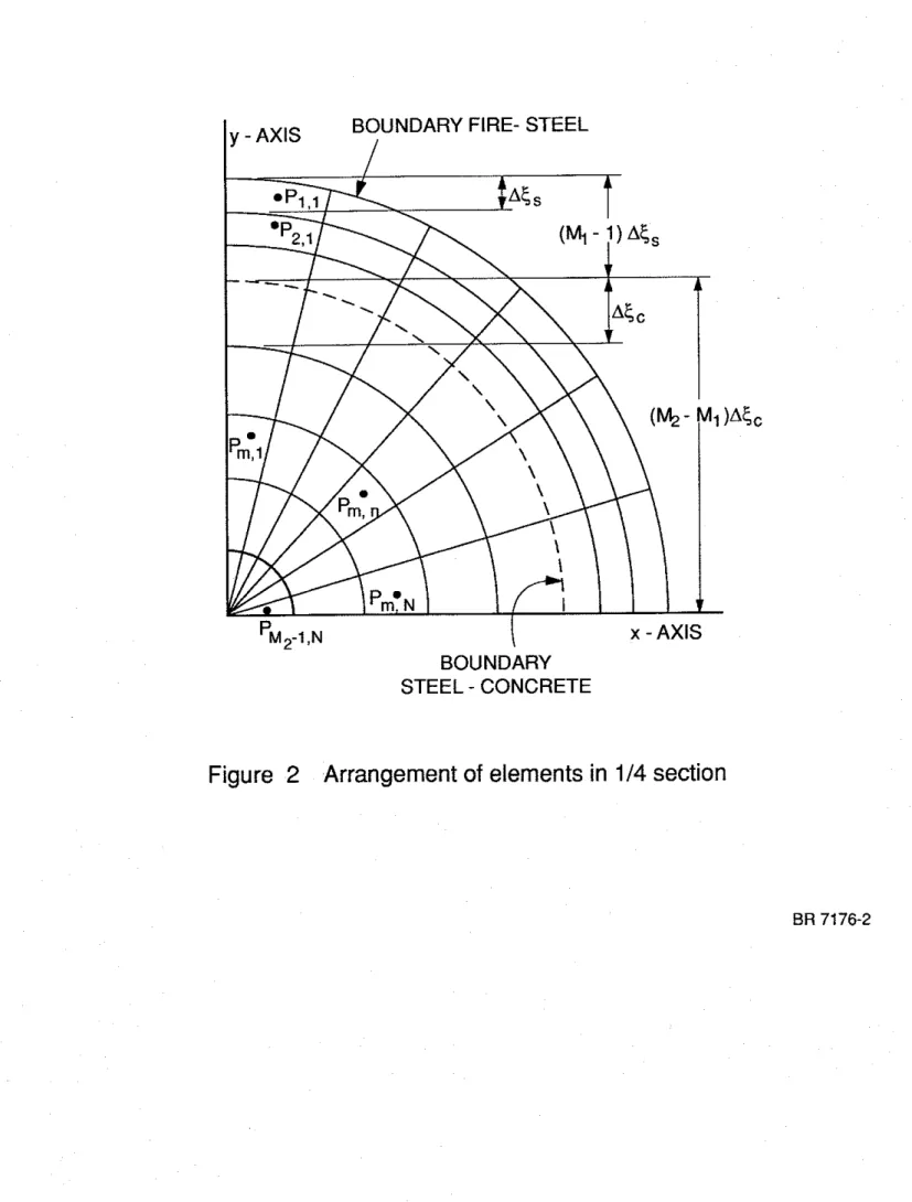
2.2.1 Division of Cross-Section into Annular Elemen&
To calculate the deformations and stresses in the column and its strength, the cross- sectional area of the column is subdivided into a number of annular elements. In Figure 2,
the arrangement of the elements is shown in a quarter section of the column. The arrangement of the elements in the three other quarter sections is identical to this. In the radial direction, the sub-division is the same as that shown in Figure 1, where the cross- section is divided into concentric layers. In the tangential direction, each quarter section layer is divided into N elements. The temperature representative of that of an element is
assumed to be equal to the temperature at its centre. It is obtained by taking the average of the temper- at the tangential boundaries of each element, previously calculated with the aid of Equations 1-15.
Thus, for an element Pmn, the representative temperature is:
where the subscripts, annular and layer, refer to the annular elements shown in Figure 2 and the element layers shown in Figure 1, respectively.
For the steel reinforcing bars, a representative bar temperature can be indicated also.
Measurements at various locations in steel bar sections durin~ fire tests showed that the diierences in temperature in the bar sections are small [8]. Kclose approximation of the average bar temperature is obtained by considering the column as consisting entirely of concrete and selecting the temperature at the location of the centre of the bar section as the representative bar temperature. Thus, for a steel reinforcing bar, the centre of whose section is located in an element Pw, the representative temperature is equal to that of P,,, which is given by Eq. (10).
Similarly, it is assumed that the stresses and deformations at the centre of an element are representative of those of the whole element
2.2.2 ~SS~mptionS in the Calculation of Strength Durin~ Fix
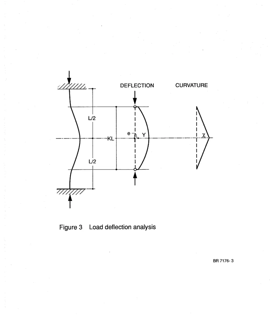
During exposure to fm, the strength of the column decreases with the duration of exDosure. The strength of the column can be calculated by a method based on a load deflection or stability analysis [9].
In this method, the columns are idealized as pin-ended columns of effective length KL [Figure 31. The load on the column is intended to be concentric. Due to imperfections of the columns and the loading device, some eccentricity exists. The loading system and the test columns were made with high precision, however. Therefore, in the calculations, a very small arbitrary load eccentricity of 0.2 mm, reflecting a nearly concentric load, has been selected for the initial eccentricity.
The curvature of the column is assumed to vary from pin-ends to midheight according to a straight line relation , as illustrated in Figure 3. For such a relation, the deflection at midheight Y, in terms of the curvature
x
of the column at this height, can be given by:For any given curvature., and thus for any given deflection at midheight, the axial strain is varied until the internal moment at the mid-section is in equilibrium with the . applied moment, i.e.,
In this way, a load-deflection curve can be calculated for any specific time during the exposure to fue. Erom these curves, the strength of the column, i.e., the maximum load that the column can cany, can be determined for each time. In the calculation of column strength, the following assumptions were made:
1. The properties of the steel and concrete are those described in the Appendix. 2. Concrete has no tensile strength.
3. Plane sections remain plane.
4. There is no slip between steel and concrete.
5. There is no composite action between the steel and concrete.
6 . The reduction in column length before exposure to fire (consisting of free shrinkage
of the concrete, creep, and shortening of the column due to load) is negligible. This reduction can be eliminated by selecting the length of the shortened column as initial length from which the changes during exposure to fire are determined.
Based on these assumptions, the column strength during exposun: to fire was calculated. In thc calculations, the network of annular elements shown in Figure 2 was used. Because the strains and stresses of the elements are not symmetrical with respect to the y-axis, the calculations were performed for both the network shown and an identical network at the left of the y-axis. The load that the column can cany and the moments in the section were obtained by adding the loads carried by each element and the moments
contributed by them.
2.2.3 muations for the Concrete
The strain in the concrete for the elements to the right of the y-axis can be given by:
and for the elements to the left of the y-axis by:
where (q), = thermal expansion of concrete mm-I
E = axial strain of the column, mm-l
x, = horizontal distance from the centre of the element to a vertical plane
through y-axis of the column section, m
p = radius of curvature, m
The stresses in the elements are calculated using the same stress-strain relations for concrete, given in Equations 25-30 in the Appendix.
2.2.4 Eouations for the Steel
The strain in an element of the steel can be given as the sum of the thermal
expansion of the steel (F&, the axial strain of the column E and the strain due to bending of
the column xJp, where xs is the horizontal distance of the steel element to the vertical plane through the y-axis of the column section and p is the radius of curvature. For the steel to the right of the y-axis (Figure 2), the strain (&)R is given by:
For the steel elements to the left of the y-axis, the strain (Q)L is given by:
The stresses in the steel are calculated using the same stress-strain relations for steel given by Equations 42-46 in the Appendix.
2.2.5 Ea-uations for the Steel Reinforcement
The strain in the steel reinforcing bars can be given as the sum of the thermal expansion of the steel (E=)B, the axial strain of the column x$p, where XB is the horizontal distance of the centre of the section of steel bar to the vertical plane through the y-axis of the column section, and p is the radius of curvature. For the steel bars at the right of the
y-axis, the strain (EB)R, is given by:
For the steel bars at the left of the y-axis, the strain (E~)L, is given by:
The stresses in the steel are calculated using the same stress-strain relations for steel, given by Equations 42-46 in the Appendix.
2.2.6 Procedure for the Calculation of Column Strength
With the aid of Equations 19-24, Equations 25-30 and Equations 42-46, the stresses at mid-section in the steel and concrete elements can be calculated for anv value of the axial strain E and curvature lip. From these stresses, the load that each element carries
and its contribution to the internal moment at mid-section can be derived. By adding the loads and moments, the load that the column carries and the total internal moment at mid- section can be calculated.
The fue resistance of the column is derivcd by calculating the strength of the column as a function of time of rue exposure. This strength rcduces gradually with time.
At a certain point, the strength becomes so low that it is no longer sufficient to support the load. At this point, the column becomes unstable and is assumed to have failed. The time to reach this failure point is the fire resistance of the column.
3 . TEST SPECIMENS
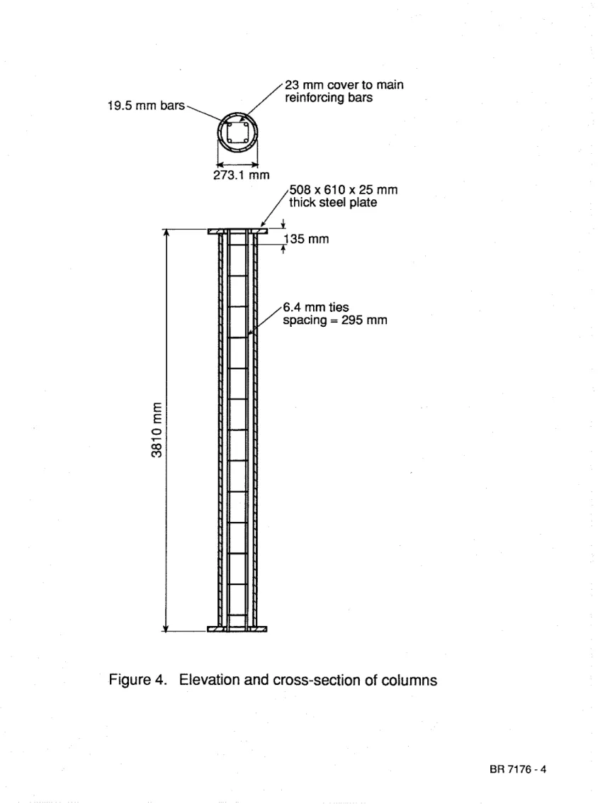
Two test specimens, consistine of circular hollow steel columns filled with
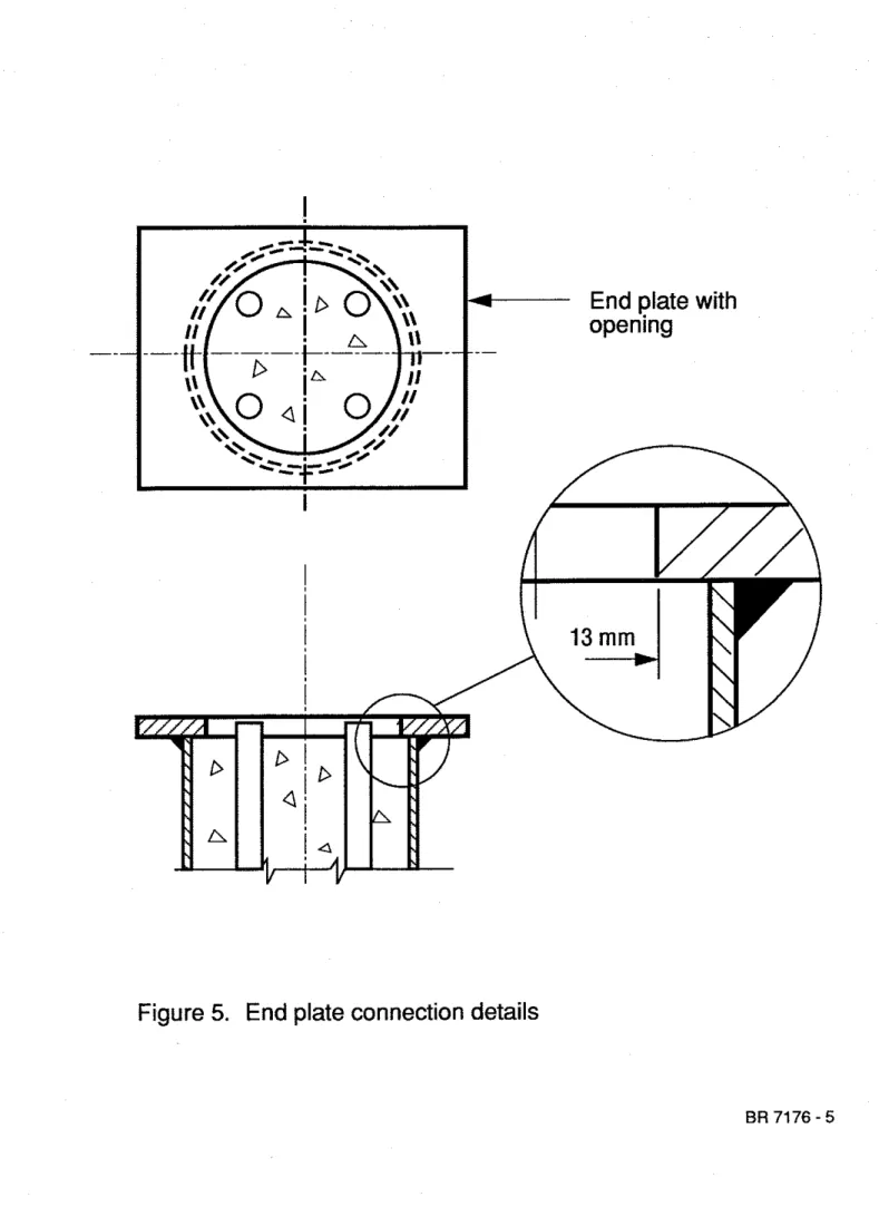
reinforced carbonate aggregate concr&, were used to verify the model given in this repon The test specimens arc described in detail in Reference 2 and an: illustrated in Figure 4.
The two columns had the same dimensions. The columns were 3810 mm long from end plate to end plate. The outside diameter was 273.1 mm and the steel wall
thickness was 6.35 mm. The steel end plates measured 508 mm wide by 610 mm long by 25 mm thick.
The steel columns were fabricated by cutting the steel to appropriate lengths. Steel and end ~ l a t e s were then welded at the column extremities. Accurate centering and
perpendcularity of the end plates were given special attention. Before weldins the end plates, a hole with a diameter 25.4
mm
smaller than the inner diameter of the hollow steel section was cut in each plate. The smaller diameter of the holes created, after welding, a lip of 13 mm, as shown in Figure 5.Four small holes were also drilled in the steel wall to provide vent holes for water vapour produced during the experiment. Two of the holes were located opposite one another at 1448 mm above midheight of the column. The other two were also located opposite to one another at 1448 m m below midheight of the column.
The steel of the columns was manufactured according to CSA Standard CAN3- G40.20-M81 [lo], Class H and had a s p e c i f ~ d yield strength of 350 m a .
Deformed bars, meeting the CSA Standard G30.12-M77 [ll] with a minimum yield strength of 400 MPa, were used for the main reinforcing and tie bars. The diameter of the main reinforcing bars was 19.5 mm. The diameter of the ties was 6.4 mm.
The main reinforcing bars were tied together to complete the steel cage. The main bars were cut 10 mm shorter than the column length. The steel cage was then placed into the column with special care to ensure appropriate centering.
The concrete was poured in the column through the top opening. Its composition, per cubic metre of concrete
mix,
was as follows:Cement 439 kg
Water 161 kg
Fine Aggregate 621 kg Coarse Aggregate 1 128 kg
The 28-day cylinder strength was approximately 42 MPa. The average cylinder strength at the time of testing was approximately 47 MPa
Chromel-alumel thermocouoles with a thickness of 0.91
mm
were installed at midheight of the column for meas&ng the temperatures of the steel, reinforcement bars and concrete at different locations in the cross-section. The locations of the thermocouples are described in detail in Reference 2.4 . TEST APPARATUS
The tests were carried out by exposing the columns to heat in a column test fumace. The test furnace was designed to produce the conditions to which a member might be subjected during a fire. It consists of a steel framework supported by four steel columns,
with the furnace chamber inside the hnework. The characteristics and instrumentation of the furnace, which has a loading capacity of 1000 t, are described in detail in Reference 12.
5 TEST CONDITIONS AND PROCEDURES 5 . 1 End conditions
The tests were carried out with both ends of the columns fured, ie., restrained against rotation and horizontal translation. For this purpose, eight 19 mm bolts spaced regularly around the column were used at each end to bolt the end plates to the loading head at the top and the hydraulic jack at the bottom.
5 . 2 Loading
Both columns were tested under a concentric load. The applied loads were 37 and 67% of the factored compressive resistance of the columns (C,) or 95 and 171% of the factored compressive resistance of the concrete core
(w,
determined according to CSA Standard CSNCAN-S16.1-M89 1131. The factored compressive resistances of eachcolumn, as well as the applied loads, are given in Table 1. The effective length factors, K, used in the calculation of the factored compressive resistances were those recommended in CSNCAN-S16.1-M89 for the given end condition, i.e., 0.65. The effective length of the columns, KL, was thus assumed to be 2.48 m.
The load was applied for approximately 45
min
before the start of the test, until a condition was reached at which no further increase of the axial deformation could be measured. This condition was selected as the initial condition for the column axial deformation. The load was maintained constant throughout the test5 . 3 Fire exposure
The ambient temperam at the start of each test was approximately 20°C. During the test, the column was exposed to heating controlled in such a way that the average temperature in the furnace followed as closely as possible the ASTM-El19 [6] or CAN/ULC-S101 [7] standard temperature-time curve.
5 . 4 Failure criterion
The columns were considered to have failed, and the tests terminated, when the hydraulic jack, which has a maximum speed of 76 d m i n , could no longer maintain the load.
5.5 Recording of results
The furnace, concrete and steel temperatures, as well as the
axial
deformations of the columns were recorded at 2-minute intervals.6. RESULTS AND DISCUSSION
Using the mathematical model described in this report, the temperatures, axial
deformations and strengths of the columns were calculated In the calculations, the thermal and mechanical properties of the concrete and steel, and the specitics of the column furnace given in the Appendix, were used.
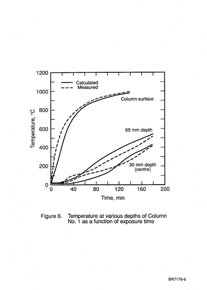
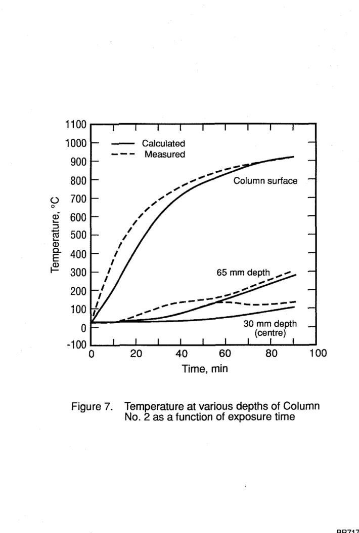
In Figs. 6 and 7, calculated temperatures are compared with the temperatures measured at the steel surface of the steel section, and the temperatures at various depths in
the concrete. It can be seen that, with the exception of the temperatures measured
ai
an early stage, there is a good agreement betweencalculated and measured columntemwratures. The temueratures measured deeper inside the column show initiallv a rel&vely rapid rise, fofiowed by a period of reiatively slow rate of temperature
&.
Thistemperature behaviour may be
the
result of thermally induced migration of the moisture towards the centre of the column where, as shown in previous tests [2], the influence of migration is most pronounced. Although the model takes into account evaporation of moisture, it does not take into account the migration of the moisture towards the centre. That migration appears to account for the deviation between calculated and measured temperatures at the earlier stages of fire exposure. At a later stage, however, which is the important stage from the point of view of predicting the ~e resistance of the columns, thereis a good agreement between calculated and measured temperatures.
In Figs. 8 and 9, the calculated and measured axial deformations of the columns during exposure to fire are shown. It can be seen that there is reasonably good agreement in the trend of deformations between calculated and measured results. There are some diierences, however, between the actual values of the calculated and measured
deformations.
It must be noted that the column deforms axially as a result of several factors, namely, load, thermal expansion, bending and creep, which cannot be completely taken into account in the calculations. Since the axial deformations, which are on the order of 20 mm, are for columns with a length of about 3800 mm, small inaccuracies in these factors may cause noticeable differences between calculated and measured axial deformations. A difference of 10% between the theoretical and actual coefficients of thermal expansion of steel, for example, will cause a difference of approximately 5 mm in the axial deformations. The effect of creep, which is more pronounced at a later stage of the fire exposure, may be even greater. Whereas the model defines the failure point as the ~ o i n t at which the column can no longer suo~ort the aDDfied load and assumes that failure at h i s point is instantaneous, during th<tests:&e col-s contracted considerably,
apparently as a result of continued loss of strength and creep, before they were crushed.
In Fig. 10, calculated column strengths as a function of the fm exposure time are shown, together with the calculated and measured fire resistances for the test loads given in Table 1. The strength decreases with time until it becomes so low that the column can no longer support the load. The time to reach this point is the fire resistance of the column. The calculated fire resistances of the columns are also given in Table 1 together with the
measured fire resistances. The results show that the calculated fire resistance of Column No. 1 is about 20 percent and that of Column 2 about 10 percent lower than the measured
contraction of the columns, which the model can only partly take into account. For practical purposes, however, the calculated fue resistances are reasonably accurate.
7 . CONCLUSIONS
Based on the results of this study, the following conclusions can be drawn:
1. The mathematical model employed in this study is capable of predicting the fire
resistance of circular columns. made of HSS filled with bar-reinforced concrete, with
an accuracy that is adequate fdr practical purposes. The results indicate that the model is conse~ative in its predictions.
2. The model will enable the expansion of data on the fire resistance of circular concrete filed steel columns, which at present consists predominantly of data for columns filled with plain concrete, with that for columns filed with bar reinforced concrete.
3 . Using the model, the fm resistance of circular concrete filled steel columns can be
evaluated for anv value of the simificant parameters, such as load, column section dimensions, col&n length and @rcenta@ of reinforcing steel, without the necessity of testing.
4. The model can also be used for the calculation of the fire resistance of columns made with concretes other than those investigated in this study, for example lightweight or siliceous aggregate concretes, if the relevant material properties are known.
NOMENCLATURE
area of element (m2) smc heat (Jkg°C) eccentricity (m) stress (MPa)
cylinder strength of concrete at temperature T (MPa) cylinder strength of concrete at room temperature (MPa) strength of steel at temperature T @Pa)
coeffcient of heat transfer at fire exposed surface (WIm2'~) thermal conductivity (WImOC)
effective length factor
length of column that contributes to axial deformation (m) unsupported length of the column (m)
number of points Pin the steel section in radial direction
total number of points P in the column section in radial direction number of elements in tangential direction
point
radius of concrete core (m) radius of steel column (m) temperature ("(2)
volume of moisture in an element (m3) coordinate (m)
coordinate (m)
Greek Letters Subscripts 0 B C f L m, MI. M2 max min n, N1 P R S T
coefficient of thermal expansion (lIoC) increment or difference
mesh width in radial direction (m) emissivity, strain (mlm)
heat of vaporization (Jkg)
density (kg/m3), radius of curvature (m) Stefan-Boltzmann constant (W/m2K4) time (h)
concentration of moisture
curvature of column at mid-height (Ym)
at room temperature of steel reinforcement of concrete
of fire
left of the x-axis
at the points m, MI, M2 in radial diction maximum
Illinhum
at the points n, N1 in tangential direction pt-g to proportional stress-strain relation right of the x-axis
of steel
perthing to temperature of water
Superscripts
REFERENCES
1. Lie, T.T., Fire Resistance of Reinforced Concrete Columns: A Parametric Study, Journal of Fire Protection Engineering. Vol.1. No.4. 1989. DD. 121-130.
2. Chabot. M.. and Lie. T.T.. ~ x k r i m e n 2 ~ ~~~ studies on the ~ G ~ e s i s t a n c e ~~ ~ ~ ~ ~ ~~~~~~~ of Hollow Steel c b l u i n s ~ i l l e d witd B&-~einforced Concrete, IRC Internal Report NO: 628, Institute for Research in Construction, National Research Council of Canada, Ottawa,
1992~
3. Dusinberre, G.M., Heat Transfer Calculations by Finite Differences, International Textbook Company, Scranton, Pennsylvania, 1961.
4. Lie, T.T., and Harmathy, T.Z., A Numerical Procedure to Calculate. the Temperature of Protected Steel Columns Exposed to Fire, Fire Study No. 28, Division of Building Research, National Research Council of Canada, NRCC 12535, Ottawa, 1972. 5 Lie, T.T., Temperature Distributions in Fire-Exposed Building Columns, Journal of
Standard Methods of Fire Test of Building Construction and Materials, ASTM E l 19- 88, American Society for Testing Materials, Philadelphia, Pennsylvania, 1990. Standard Methods of Fire Endurance Tests of Building Construction and Materials, CAN4-S101-M89, Underwriters' Laboratories of Canada, Scarborough, Ontario,
1989.
Lie, T.T., Lin, T.D., Allen, D.E., and Abrams, M.S., Fire Resistance of Reinforced
Concrete Columns, National Research Council of Canada, Division of Building Research, NRCC 23065, Ottawa, 1984,32 pp.
Allen, D.E. and Lie, T.T., Further Studies of the Fire Resistance of Reinforced Concrete Columns, National Research Council of Canada, Division of Building Research, NRCC 14047, Ottawa, 1974.
General Requirement for Rolled or Welded Quality Steel, CAN3-G.40.20-M81, Canadian Standards Association, Toronto, Ontario, 1981.
Billet-Steel Bars for Concrete Reinforcement, CAN3-G30.12-M77, Canadian Standards Association, Toronto, Ontario, 1977.
Lie, T.T., New Facility to Determine the F i e Resistance of Columns, Canadian Journal of Civil Engineering, Vol. 7, No. 3, 1980, pp. 551-558.
Lit States Design of Steel Structlues - CANICSA-S16.1-M89, Canadian Standards Association, Toronto, Ontario, 1989.
Lie, T.T. and Chabot, M., A Method to Predict the Fire Resistance of Circular Concrete Filled Hollow Steel Columns, Journal of F i e Protection Engineering, V01.2, NO. 4, 1990, pp. 111-126.
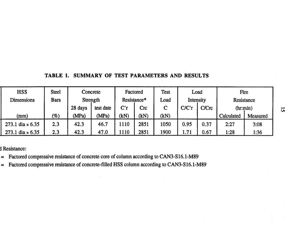
TABLE 1. SUMMARY OF TEST PARAMETERS AND RESULTS
*Factored Resistance:
C'r = Factored compressive resistance of concrete core of column according to CAN3-S16.1-M89 Crc = Factored compressive resistance of concrete-filled HSS column according to CAN3-S16.1-M89 Column No. 1 2 Steel Bars 2.3 2.3 HSS Dimensions (mm) 273.1 dia x 6.35 273.1 dia x 6.35 Concrete Strength 28 days W a ) 42.3 42.3 test date W a ) 46.7 47.0 Test Load C (kN) 1050 1900 Factored Resistance* C'r (kN) 1110 1110 Load Intensity Crc
OcN)
2851 2851 CIC'r 0.95 1.71 Fire Resistance (hr:min) UCrc 0.37 0.67 Calculated 2:27 1:28 Measured 3:08 1:36APPENDIX: MATERIAL PROPERTIES AND SPECIFICS OF COLUMNS AND FURNACE
The values of the material properties used in this study are the same a s those used in
References 8 and 14 for the calculation of the fire resistance of reinforced concrete columns
and concrete-filled steel columns, with the exception of the thermal properties of the concrete. These properties, which in References 8 and 14 apply to siliceous aggregate concrete, have been replaced by those of carbonate aggregate concrete, which have been measured recently. CONCRETE PROPERTIES Stress-strain relations where Em= = 0.0025
+
(6.0T+
0.04T2) x 1@ and for O°C<
T < 450°C f c = Q for 450°C I T 1874OC fc =fco
[2.011 - 2.353(=)I
for T > 874OCfc
= 0 Thermal capacity for 0 I T 1400°C pccc = 2.566 x lo6 J mJ°C-I for 400 < T I 410°C pccc = (0.1765T - 68.034)x
lo6 J m-3OC-Ifor 445 < T I 500°C ps, = 2.566 x lo6 J rn-3"C'' for 500 < T I 635°C pccc = (0.01603T - 5.44881)
x
lo6 J m-3OC-I for 635 <T1715"C pccc = (0.16635T - 100.90225) x lo6 J m-30C-' for 715 < T 5 785°C pccc = (-0.22103T+
176.07343) x lo6 J m-3°C'' for T > 785°C p s c = 2.566 x lo6 J m""C-' Thermal eonduetivity for 0 1 T 1 293°C k, = 1.355 W m-1°C1 for T > 293°C k, =-0.001241T+
1.7162 W m-l°C1Coefficient of thermal expansion
STEEL PROPERTIES Stress-strain relations where Ep = 4 X 10⁻⁶ fyo and f(T,001) = (50 - O.04T)
x
[1 - exp((-30+
0.03~)10,001)]x
6.9where
~T,(E, - Ep
+
0.001)) = (50 - 0.04T) X[I - exp((-30+
0.03T)f(~, - Ep+
O.OOIJ)] X 6.9 (46) Thermal capacity for 0°C I T I 650°C p,c, = (0.004T+
3.3) x lo6 J rn-3"C-' for 650°C < T 1 725°C p,c, = (0.068T+
38.3) x lo6 J m-30C-1 for 725°C < T I 800°C p,c, = (-0.086T+
73.35) x lo6 J m-3OC-' for T > 800°C p,c, = 4.55 x lo6 J rn3"~-' Thermal conductivity for 0°C I T 5 900°C k, =-
0.022T+
48 W m-1°C-' for T > 900°C k, = 28.2 Wrn-l0c-'
Coefficient of thermal expansion
for T < 1000°C a, = (0.004T
+
12) X 10" "C-' for T 2 1000°C a,= 16x 10" OC-' WATER PROPERTIES Thermal capacity p,,.c, = 4.2 xlo6
3 m-3°C' Heat of vaporization&,
= 2.3 x lo6 J kg-'SPECIFICS
OF
COLUMN
AND
FIRE
&f = emissivity of fire: 0.75 Q = emissivity of steel: 0.80
KL
=
effecitve length of columns: 2.0m
forfire
resistance calculations 1=
length of column that contributes to axial deformation: 3.5 m (I=
concentration of moisture in concrete by volume: 0.10Figure
1
Arrangement of layers in section of concrete filled steel
column
ly
-AXIS BOUNDARY FIRE- STEELx -AXIS
BOUNDARY STEEL - CONCRETE
CURVATURE
23 mm cover to main reinforcing bars 19.5 mrn bars
Calculated
--
-
Measuredt -
7-
-
Column surface-
-
-
65 mm depth-
0
40
80
120
160
200
Time, min
Figure
6.
Temperature at various depths of Column
11
00
1 1 I I I I I I I1000
-
CalculatedTime, min
Figure
7.
Temperature at various depths of Column
I I I I I I I I I
-
-
---
Calculated
-I \Measured
-
-
\-
\ \-
\ \ \ \-
\-
\ \ \-
\-
I-
1-
I I I I I I I I I0
40
80
120
160
200
Time, min
Figure
8.
Calculated and measured axial
deformations of Column
No.
1 as a
function of exposure time
Figure
9.
Calculated and measured axial
deformations of Column No.
2
as a
function of exposure time
10
I I I I I I I I I-
Calculated5
-
---
Measured-
0
-
EE
-5
-
c"-
0.-
5
E
-10
8
LC a,- 1 5 -
-
.-
a
-20
-25
-30
'\-
\-
\ \ \ \-
\ \-
\ \-
\ \-
\- I I I I I I I I I 0 20 40 60 80 100Time, min
5000 I I I I I I I I I I
-
Calculated fire resistance