HAL Id: hal-00881457
https://hal.archives-ouvertes.fr/hal-00881457
Submitted on 8 Nov 2013
HAL is a multi-disciplinary open access
archive for the deposit and dissemination of
sci-entific research documents, whether they are
pub-lished or not. The documents may come from
teaching and research institutions in France or
abroad, or from public or private research centers.
L’archive ouverte pluridisciplinaire HAL, est
destinée au dépôt et à la diffusion de documents
scientifiques de niveau recherche, publiés ou non,
émanant des établissements d’enseignement et de
recherche français ou étrangers, des laboratoires
publics ou privés.
Modular simulation and optimization of an 12MW
industrial gasifier
Xavier Joulia, Pascal Floquet, Rodolphe Sardeing, Olivier Baudoin, Madeleine
Vieville, Valérie Brousse
To cite this version:
Xavier Joulia, Pascal Floquet, Rodolphe Sardeing, Olivier Baudoin, Madeleine Vieville, et al.. Modular
simulation and optimization of an 12MW industrial gasifier. European Symposium on
Computer-Aided Process Engineering - ESCAPE 20, Jun 2010, Ischia, Italy. pp. 703-708. �hal-00881457�
O
pen
A
rchive
T
OULOUSE
A
rchive
O
uverte (
OATAO
)
OATAO is an open access repository that collects the work of Toulouse researchers and
makes it freely available over the web where possible.
This is an author-deposited version published in :
http://oatao.univ-toulouse.fr/
Eprints ID : 10017
To cite this version : Joulia, Xavier and Floquet, Pascal and Sardeing, Rodolphe and Baudoin,
Olivier and Vieville, Madeleine and Brousse, Valérie. Modular simulation and optimization of
an 12MW industrial gasifier. (2010) In: European Symposium on Computer-Aided Process
Engineering - ESCAPE 20, 06 June 2010 - 09 June 2010 (Ischia, Italy).
Any correspondance concerning this service should be sent to the repository
administrator: [email protected]
Modular Simulation and Optimization of an 12MW
Industrial Gasifier
X. Joulia(1), P. Floquet(1), R. Sardeing(2), O. Baudoin(2), M. Vieville(3), V. Brousse(3)
(1)University of Toulouse, Laboratoire de Génie Chimique, UMR CNRS 5503, INP-ENSIACET, 4 Allée Emile Monso, BP 44362, 31432 Toulouse Cedex 4, FRANCE.
[email protected], [email protected]
(2)ProSim, Stratège Bâtiment A, BP 27210, F-31672 Labège Cedex, France (3)Europlasma, 21 rue Daugère, 33520 Bruges
Abstract
In this work, a flexible model, built from elementary modules, is developed for an industrial waste gasification process, in an industrial moving bed reactor located in Morcenx (France). This gasifier is able to treat more than 46,875 ton/year of RDF (Refused Derived Fuel) waste for producing 12 MW. Drying, pyrolysis, combustion / gasification and plasma polishing are used to convert waste directly into a synthesis gas composed of carbon monoxide and hydrogen. This synthesis gas is then used for producing electricity via gas engine.
Keywords: Modular Simulation, Gasifier, Optimization, Synthesis Gas
1.
Introduction
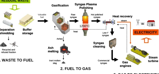
The objective is to turn waste power potential into electricity with an environment friendly process. The gasifier is designed to treat 6.25 t/h of Refused Derived Fuel (RDF) waste for producing 12 MW. The three main steps of conversion of waste to gas and electricity are shown in figure 1.
Figure 1: Main steps of the conversion of RDF waste to gas and electricity
Valuable fuel
1. WASTE TO FUEL
Gasification Syngas Plasma Polishing
Raw
syngas Heat recovery steam heat Syngas cleaning Separation shredding Buffer storage Ash melting Hot polished syngas Commercial syngas heat Low t° syngas ELECTRICITY RESIDUAL WASTE 2. FUEL TO GAS 3. GAS TO ELECTRICITY Gas engines Steam turbine Recycled and refused fraction Ashes Inert molten slag 1200°C Valuable fuel 1. WASTE TO FUEL
Gasification Syngas Plasma Polishing
Raw
syngas Heat recovery steam heat Syngas cleaning Separation shredding Buffer storage Ash melting Hot polished syngas Commercial syngas heat Low t° syngas ELECTRICITY RESIDUAL WASTE 2. FUEL TO GAS 3. GAS TO ELECTRICITY Gas engines Steam turbine Recycled and refused fraction Ashes Inert molten slag 1200°C
We are interested in the second step of this scheme. Firstly the material system is briefly described. Then, the modeling approach of the three chambers of the gasifier is studied. Finally, some results on a case study, sensitivity analysis and conclusions are given.
2.
Material system
The material system under consideration contains solids and gases. The main assumptions for modeling this material system are the following.
2.1.Solids
Three solids are considered in the model: the fuel part of the waste (FPW), the char and the ashes. The FPW constitutes the dry part of the waste, without ashes. It is defined from its atomic composition as an equivalent molecule: . The fundamental property of RPW is its Lower Heating Value (LHV). Although some correlations have been proposed for its estimation (Niessen, 2002, Higman and Van der Burgt, 2003, Riazzi, 2005, Pröll and Hofbauer, 2008, Antonini, 2003,) it is better to determine its value from experimental data. The char is the solid residue coming out pyrolysis. Its properties are assimilated to pure carbon. The percentage of carbon grows with the pyrolysis temperature and it is approximately 90% at 700°C (Nozahic, 2008). The soots are not taken into account. Finally, ashes that are the mineral part of the waste are taken into account only for mass and energy balances and are considered as chemically inert.
The properties of ashes are assimilated to those of SiO2.
2.2.Gases
The gases under consideration are the following:
• O2, N2 for the air feedstreams (drying, combustion and decarbonation
sections);
• Water for the waste and air moisture. Water is also a pyrolysis product;
• H2, CO, CO2 that are combustion/pyrolysis/gasification products;
• CH4 is also a pyrolysis product;
• Tar is assimilated to a toluene/naphtalene mixture.
Some gaseous pollutants are also considered in this study: NO, NO2, SO2 and H2S
resulting from nitrogen and sulfur present in the waste.
3.
Gasifier Modeling
The technology used by Europlasma for the waste gasification is confidential. It is a moving bed with three chambers. For modeling purposes, the gasifier is divided in five main sections, in agreement with the gasifier structure and the elementary physico-chemical phenomena. The schematic representation of the gasifier model with all elementary components is presented on figure 2. The sections are the following:
• Drying section (chamber 1) in which waste moisture is decreasing.
• Flash pyrolysis section (chamber 2.1). This first step of the waste
thermochemical transformation produces a gaseous phase, containing carbon monoxide, carbon dioxide, methane, hydrogen and water but also pollutants and tar and a solid phase, the char.
4 3 2 1 ξ ξ ξ ξO N S CH
• Combustion/gasification section (chamber 2.2) of the char. Combustion is exothermic and is the energy source for balancing the endothermicity of gasification and pyrolysis. The plug-dispersion flow of the waste inside the gasifier chamber 2 is represented by a series of perfect mixing reactors 2.2.i.
• Decarbonation section (chamber 3). In this last step, the residual char is almost
totally gasified by supplementary air in order to respect environmental constraint of carbon content in waste ashes: mass fraction of C less than 3 %.
• All gases produced in the three previous sections (pyrolysis, combustion /
gasification and decarbonation) are then collected in the main chamber of the gasifier (chamber 2.3) where gas phase reactions, such as water gas shift, are occurring.
Figure 2: Schematic representation of the gasifier model
Chamber 2.1 : Pyrolysis Perfect Mixing CO + H2O CO2+ H2 S o lid s P lu g – d is p e rs io n f lo w re p re s e n te d b y n R A C in s e ri e s C + O2 CO2 C + CO2 2CO C + H2O CO + H2 Chamber 2.2.1 Combustion / Gasification C + O2 CO2 C + CO2 2CO C + H2O CO + H2 Chamber 2.2.n Combustion / Gasification C, Ashes CO, CO2, H2O H2, N2 CO, CO2, H2O H2, N2 O2, N2 Chamber 2.3 Gas phase C, Ashes H2, CO, CO2, H2O, C7H8, C10H8, H2S, SO2, NO, NO2 CHξ1Oξ2Nξ3Sξ4 H2, CO, CO2, H2O, C7H8, C10H8, H2S, SO2, NO, NO2 CHξ1Oξ2Nξ3Sξ4, m’H2O, Ashes Chamber 1 Drying A A T Air, x% H2O Air, x’% H2O Waste : CHξ1Oξ2Nξ3Sξ4, mH2O, Ashes A H2, CO, CO2, H2O, C7H8, C10H8, H2S, SO2, NO, NO2, N2 C, Ashes Chamber 3 : Decarbonation CO, CO2, H2O, H2, N2 C + O2 CO2 C + CO2 2CO C + H2O CO + H2 A O2, N2 O2, N2 C, Ashes
A Adiabatic reactor T Fixed temperature reactor
Chamber 2.1 : Pyrolysis Perfect Mixing CO + H2O CO2+ H2 S o lid s P lu g – d is p e rs io n f lo w re p re s e n te d b y n R A C in s e ri e s C + O2 CO2 C + CO2 2CO C + H2O CO + H2 Chamber 2.2.1 Combustion / Gasification C + O2 CO2 C + CO2 2CO C + H2O CO + H2 Chamber 2.2.1 Combustion / Gasification C + O2 CO2 C + CO2 2CO C + H2O CO + H2 Chamber 2.2.n Combustion / Gasification C + O2 CO2 C + CO2 2CO C + H2O CO + H2 Chamber 2.2.n Combustion / Gasification C, Ashes CO, CO2, H2O H2, N2 CO, CO2, H2O H2, N2 O2, N2 Chamber 2.3 Gas phase C, Ashes H2, CO, CO2, H2O, C7H8, C10H8, H2S, SO2, NO, NO2 CHξ1Oξ2Nξ3Sξ4 H2, CO, CO2, H2O, C7H8, C10H8, H2S, SO2, NO, NO2 CHξ1Oξ2Nξ3Sξ4, m’H2O, Ashes Chamber 1 Drying A A T Air, x% H2O Air, x’% H2O Waste : CHξ1Oξ2Nξ3Sξ4, mH2O, Ashes A H2, CO, CO2, H2O, C7H8, C10H8, H2S, SO2, NO, NO2, N2 C, Ashes Chamber 3 : Decarbonation CO, CO2, H2O, H2, N2 C + O2 CO2 C + CO2 2CO C + H2O CO + H2 A O2, N2 O2, N2 C, Ashes
The two main assumptions of the model are the adiabaticity of the whole gasifier and the absence of cracking reactions. This last one is justified by the fact that, by using
plasma technology, all organics are then transformed into CO/H2 (see figure 1).
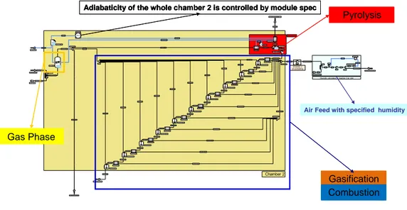
Each section model is built from elementary standard modules of the ProSimPlus®
simulator. As illustration, figure 3 shows the simulation diagram of the chamber 2 where occur pyrolysis, combustion and gasification. The gasifier simulation diagram is obtained by aggregation of the sub-diagrams.
Figure 3: ProSimPlus® simulation diagram of the gasifier chamber 2
The model fundamental parameters concerns pyrolysis and are the ratio of pyrolysed
carbon, τ, and the composition of the pyrolysis gas. These parameters are estimated
from thermogravimetric experimental data.
4.
Case study results
For the case study, the mass composition of the fuel part of the waste (FPW) is the following: C: 0.657929, H: 0.091236, O: 0.248008, N: 0.00257, S: 0,000257. Taking into account the moisture and ashes, the waste formula is:
CH1.6525O0.2830N0.0033S0.0001, 0.09636H2O, 0.05625SiO2
The FPW lower heating value is estimated to 27330 kJ/kg. The waste total flowrate is 6.25t/h. The characteristics of the air feeds for drying, combustion and decarbonation are respectively:
- total flowrates: 4435, 9790 and 1000 Nm3/h
- temperatures, after preheating: 360, 600 and 600°C
Co mb us ti on_06 C2 _M C2 _S C2_ Al i m _Hu mi d ité_Air M_ CG WS Bi l an _ Th e rmique M _Ph as e_Gaz C2 _Su rp l u s_ Humidité E20 0
Humidity calculation of chamber 2 air inlet
Co mb u sti on_02 Gaz é ifi c ation_ 02
C2 _E SPEC C2 _ SPEC_ T r Chamber 2 air preheating AAA1 C2 _ TR
Gaz é ifi c ation_08 Co mb u sti on_08 Gaz é i fi c a tion_09 D_ Ali m _CG_02 Co mb u sti on_07 Ga zé i fic a tion_04 Com bu s ti on_04 Ga z éi fi ca tion_07 D_ Ali m _CG_01 Gaz é i fi c a tion_10 Ga z éi fi ca tion_06 Ci el _ Gazeux Co mb u sti on_02 Com bu s tion_09 Com bu s tion_10
Gaz é ifi c ation_02 Gaz é ifi c ation_01
Chamber 2 T_ Sol i d e_ Pyrolyse Co m bu s ti on_01 SPEC SPEC_Bi l an Co mb us ti on_05 Dé c om p osition Dé vo l ati l i sation Ga zé i fi ca tion_05 Gaz _ Py rolyse So l i de _ Py rolyse Ga z _CG_ 0 1 So li d e _CG_01 Com b_01 Gaz _ CG_ 02 Sol i d e_ CG_02 Al i mGa z_ CG_02 Com b_02 Ga z_ Cha mbre2 Gaz _CG
Al i mGa z_ CG Com b_03 Sol i d e_ CG_03 Al i mGa z_ CG_03 Gaz _ CG_ 03 Co mb_04 So l id e _CG_04 Ali m Ga z _CG_04 Gaz _ CG_ 04 Co mb_05 So l i de _ CG_05 Al i mGaz _ CG_05 Ga z _CG_0 5 Co m b_06 Sol i de _ CG_06 Al i m Ga z _CG_06 Ga z_ CG_ 0 6 Ali m Ga z _CG_bis Com b_07 Sol i d e_ CG_07 Ali m Ga z _CG_07 Ga z _CG_0 7 Com b_08 Sol i d e_ CG_08 Al i mGa z_ CG_08 Gaz _ CG_ 08 Co mb_09 So l id e _CG_09 Al i mGa z_ CG_09 Ga z_ CG_ 0 9 Co mb_10 Ve rs d é ca rb on a tation So li d _ CG_10 Ali m Ga z _CG_10 Ga z_ CG_ 10
Gaz d e d é ca rbo n atation Gaz d e p ro du ction
Syn the s i s_Gas
C2 _2 Ai r se c de d éc a rb o natation Com bu s tio n_Gas C2_ 3 C2 _4 C2 _5
C2_ DTr
C2 _ D(Eau )
C2 _Ai r_Hu mi d e_ Froid C2 _ 6 Ga z _Dé vola
T (Ci el _ Gaz eux) D(Bi l a n)
T(Py ro l yse)
So li d e _Dévola Sol i d es v en a nt d e la Chambre 1
Dry _So lids
El em ents
Al im Gaz _ CG_01
Pyrolysys
Chamber 2: Pyrolysys - Combustion - Gazification
WSDHR_ Pyro Ordre 21 De T (Ce n dres) XT HERM O Gaz _ Ci e l _Gazeux Ex cè s _Solides Sol i d es _ en_excès Ord re_ 3 1
Dec arb o _Gas
Eq ui l i brage
Pyrolysis
Gasification Combustion Gas Phase
Adiabaticity of the whole chamber 2 is controlled by module spec
Air Feed with specified humidity
Co mb us ti on_06 C2 _M C2 _S C2_ Al i m _Hu mi d ité_Air M_ CG WS Bi l an _ Th e rmique M _Ph as e_Gaz C2 _Su rp l u s_ Humidité E20 0
Humidity calculation of chamber 2 air inlet
Co mb u sti on_02 Gaz é ifi c ation_ 02
C2 _E SPEC C2 _ SPEC_ T r Chamber 2 air preheating AAA1 C2 _ TR
Gaz é ifi c ation_08 Co mb u sti on_08 Gaz é i fi c a tion_09 D_ Ali m _CG_02 Co mb u sti on_07 Ga zé i fic a tion_04 Com bu s ti on_04 Ga z éi fi ca tion_07 D_ Ali m _CG_01 Gaz é i fi c a tion_10 Ga z éi fi ca tion_06 Ci el _ Gazeux Co mb u sti on_02 Com bu s tion_09 Com bu s tion_10
Gaz é ifi c ation_02 Gaz é ifi c ation_01
Chamber 2 T_ Sol i d e_ Pyrolyse Co m bu s ti on_01 SPEC SPEC_Bi l an Co mb us ti on_05 Dé c om p osition Dé vo l ati l i sation Ga zé i fi ca tion_05 Gaz _ Py rolyse So l i de _ Py rolyse Ga z _CG_ 0 1 So li d e _CG_01 Com b_01 Gaz _ CG_ 02 Sol i d e_ CG_02 Al i mGa z_ CG_02 Com b_02 Ga z_ Cha mbre2 Gaz _CG
Al i mGa z_ CG Com b_03 Sol i d e_ CG_03 Al i mGa z_ CG_03 Gaz _ CG_ 03 Co mb_04 So l id e _CG_04 Ali m Ga z _CG_04 Gaz _ CG_ 04 Co mb_05 So l i de _ CG_05 Al i mGaz _ CG_05 Ga z _CG_0 5 Co m b_06 Sol i de _ CG_06 Al i m Ga z _CG_06 Ga z_ CG_ 0 6 Ali m Ga z _CG_bis Com b_07 Sol i d e_ CG_07 Ali m Ga z _CG_07 Ga z _CG_0 7 Com b_08 Sol i d e_ CG_08 Al i mGa z_ CG_08 Gaz _ CG_ 08 Co mb_09 So l id e _CG_09 Al i mGa z_ CG_09 Ga z_ CG_ 0 9 Co mb_10 Ve rs d é ca rb on a tation So li d _ CG_10 Ali m Ga z _CG_10 Ga z_ CG_ 10
Gaz d e d é ca rbo n atation Gaz d e p ro du ction
Syn the s i s_Gas
C2 _2 Ai r se c de d éc a rb o natation Com bu s tio n_Gas C2_ 3 C2 _4 C2 _5
C2_ DTr
C2 _ D(Eau )
C2 _Ai r_Hu mi d e_ Froid C2 _ 6 Ga z _Dé vola
T (Ci el _ Gaz eux) D(Bi l a n)
T(Py ro l yse)
So li d e _Dévola Sol i d es v en a nt d e la Chambre 1
Dry _So lids
El em ents
Al im Gaz _ CG_01
Pyrolysys
Chamber 2: Pyrolysys - Combustion - Gazification
WSDHR_ Pyro Ordre 21 De T (Ce n dres) XT HERM O Gaz _ Ci e l _Gazeux Ex cè s _Solides Sol i d es _ en_excès Ord re_ 3 1
Dec arb o _Gas
Eq ui l i brage Pyrolysis Pyrolysis Pyrolysis Gasification Combustion Gasification Combustion Gasification Gasification Combustion Combustion Gas Phase Gas Phase Gas Phase
Adiabaticity of the whole chamber 2 is controlled by module spec Adiabaticity of the whole chamber 2 is controlled by module spec
Air Feed with specified humidity Air Feed with specified humidity
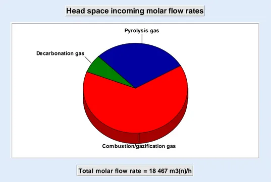
With these data, the temperature in the gasifier chamber 2, where take place pyrolysis, combustion and gasification, is 750 °C. The repartition of the head space incoming molar flowrates are shown in figure 4. Most of gas, 64 mol%, is produced by combustion / gasification. The contribution of pyrolysis gas is 29 mol% and 7 mol% is coming from decarbonation.
Figure 4: Head space incoming molar flowrates
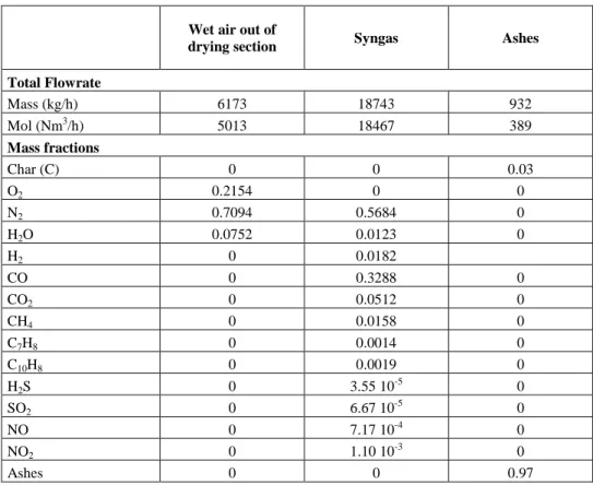
Table 1 shows the results obtained by simulation. The IHP of the syngas is
5157 kJ/Nm3.
From sensitivity analysis, two model parameters appear essential in order to have a good representation of the gasifier operation: the waste LHV and the waste carbon conversion rate into pyrolysis gas. The first fixed the thermal power available while the second specifies the repartition between the exothermicity and endothermicity potential. Their balancing, to ensure the gasifier adiabaticity, determines the operating temperature of the gasifier.
5.
Conclusion
In this paper, we have proposed an original approach for the modeling of an industrial gasifier. The gasifier model is built up in three steps: decomposition in elementary components associated to gasifier structure and physicochemical phenomena and
definition of subsystems; build up of the ProSimPlus® simulation diagrams of the
subsystems from standard modules; aggregation of the sub diagrams to obtain the whole gasifier model. The first results obtained are physically correct, allowing the use of the model as decision-making tool for process design and operation. Notably a sensitivity
Head space incoming molar flow rates
Total molar flow rate = 18 467 m3(n)/h Pyrolysis gas
Com bustion/gazification gas Decarbonation gas
analysis of the gasifier with respect to its operating parameters is currently underway. The final goal is to improve the efficiency of the waste conversion into electricity. Additional experimental tests related to waste characterization and their pyrolysis are scheduled for definitively validating the proposed model.
Wet air out of
drying section Syngas Ashes
Total Flowrate Mass (kg/h) 6173 18743 932 Mol (Nm3/h) 5013 18467 389 Mass fractions Char (C) 0 0 0.03 O2 0.2154 0 0 N2 0.7094 0.5684 0 H2O 0.0752 0.0123 0 H2 0 0.0182 CO 0 0.3288 0 CO2 0 0.0512 0 CH4 0 0.0158 0 C7H8 0 0.0014 0 C10H8 0 0.0019 0 H2S 0 3.55 10-5 0 SO2 0 6.67 10 -5 0 NO 0 7.17 10-4 0 NO2 0 1.10 10-3 0 Ashes 0 0 0.97
Table 1: Simulation results
References
G. Antonini, Traitements thermiques des déchets. Processus thermochimiques. Techniques de l’Ingénieur, G2050, 2003
C. Higman, M. Van der Burgt, Gasification, Elsevier, 2003
W.R. Niessen, Combustion and Incineration Processes., Marcel Dekker, 3rd Edition, 2002
F. Nozahic, Production de gaz de synthèse par interactions à haute température du gaz, des goudrons et du résidu carboné issus de la pyrolyse de biomasses. Institut National Polytechnique de Toulouse, PhD Thesis, 2008
T. Pröll, H. Hofbauer, Development and Application of a Simulation Tool for Biomas, Gasification Based Processes, International Journal of Chemical Reactor Engineering, 6, A89, 2008