Publisher’s version / Version de l'éditeur:
Canadian Metallurgical Quarterly, 44, 4, pp. 495-504, 2005-10-01
READ THESE TERMS AND CONDITIONS CAREFULLY BEFORE USING THIS WEBSITE. https://nrc-publications.canada.ca/eng/copyright
Vous avez des questions? Nous pouvons vous aider. Pour communiquer directement avec un auteur, consultez la
première page de la revue dans laquelle son article a été publié afin de trouver ses coordonnées. Si vous n’arrivez pas à les repérer, communiquez avec nous à PublicationsArchive-ArchivesPublications@nrc-cnrc.gc.ca.
Questions? Contact the NRC Publications Archive team at
PublicationsArchive-ArchivesPublications@nrc-cnrc.gc.ca. If you wish to email the authors directly, please see the first page of the publication for their contact information.
Archives des publications du CNRC
This publication could be one of several versions: author’s original, accepted manuscript or the publisher’s version. / La version de cette publication peut être l’une des suivantes : la version prépublication de l’auteur, la version acceptée du manuscrit ou la version de l’éditeur.
Access and use of this website and the material on it are subject to the Terms and Conditions set forth at
Effect of Ductile Thermal Spray Coatings on Fatigue Performance of
7075-T651 Aluminum Alloy
Arsenault, B.; Lynn, A. K.; Duquesnay, D. L.
https://publications-cnrc.canada.ca/fra/droits
L’accès à ce site Web et l’utilisation de son contenu sont assujettis aux conditions présentées dans le site LISEZ CES CONDITIONS ATTENTIVEMENT AVANT D’UTILISER CE SITE WEB.
NRC Publications Record / Notice d'Archives des publications de CNRC:
https://nrc-publications.canada.ca/eng/view/object/?id=7b1b97f7-5d25-43cc-8114-4dd852c4dce4 https://publications-cnrc.canada.ca/fra/voir/objet/?id=7b1b97f7-5d25-43cc-8114-4dd852c4dce4495
EFFECT OF DUCTILE THERMAL SPRAY COATINGS ON
FATIGUE PERFORMANCE OF 7075-T651 ALUMINUM ALLOY
B. ARSENAULT1, A.K. LYNN2 and D.L. DUQUESNAY3
1Industrial Materials Institute, National Research Council Canada,
Boucherville, Québec, Canada
2Cambridge Centre for Medical Materials, Department of Materials Science and Metallurgy,
University of Cambridge, New Museums Site, Cambridge, United Kingdom
3Department of Mechanical Engineering,
Royal Military College of Canada, Kingston, Ontario, Canada
(Received in revised form May, 2005)
Abstract — The fatigue behaviour of 7075-T651 Al alloy with ductile aluminum thermal sprayed
coatings deposited by four different commercial arc spray devices (guns) has been characterized. Coated specimens as well as polished and shot peened specimens were evaluated under fully reversed uniaxial loading at a constant amplitude of ±225 MPa. While the shot peening pretreatment was observed to increase the fatigue resistance of polished specimens, application of the coatings subsequently reduced fatigue life to below that of the original polished coupons. Changes in the residual stress state of the shot peened surface were identified as the most likely source of these reductions, even though no microstructural changes in the substrate were perceptible. Variations in fatigue life were also observed between the coatings resulting from the four spray guns. The roles of surface roughness and coating delamination in producing these decreases were investigated and stress concentrations resulting from coating delamination were identified as the primary detrimental factor affecting fatigue resistance.
Résumé — On a caractérisé le comportement de fatigue de l’alliage d’Al 7075-T651 avec des
revêtements ductiles d’aluminium déposés par métallisation à chaud au moyen de quatre dispositifs (fusils) commerciaux différents de fusion en arc électrique. On a évalué des échantillons revêtus ainsi que des échantillons polis et traités par grenaillage sous une charge uniaxe entièrement alternée à une amplitude constante de ± 225 MPa. Alors que l’on a observé que le prétraitement par grenaillage augmentait la résistance à la fatigue des spécimens polis, l’application des revêtements réduisait ultérieurement l’endurance au-dessous de celle des échantillons polis originaux. On a identifié des changements dans l’état de contrainte résiduelle de la surface traitée par grenaillage comme étant la source la plus probable de ces réductions, même si aucun changement de la microstructure dans le substrat n’était perceptible. On a également observé des variations dans l’endurance entre les revêtements résultant des quatre fusils de métallisation. On a investigué le rôle de la rugosité de surface et du délaminage du revêtement sur la production de ces diminutions et l’on a identifié la concentration des contraintes résultant du délaminage du revêtement comme facteur défavorable primaire affectant la résistance à la fatigue.
INTRODUCTION
The effect of thermal spray coatings on the fatigue behaviour of various substrate materials has attracted increased attention in recent years. Coatings providing thermal barrier capacities [1], corrosion and wear resistance [2] and other specialized functions [3] are being applied with increasing frequency to extend the service life of load bearing components. As these technologies evolve, the accumulation of mechanical fatigue
damage will play an increasingly important role in determining the ultimate mechanisms of component failure.
Application of coatings to metallic substrates has long been recognized to have a marked effect on fatigue behaviour. The magnitude of this effect can, however, vary drastically depending on coating type [4], coating thickness [5], spray parameters [4] and substrate pretreatment [6,7] with the application of a coating leading to increased fatigue life in some cases and reduced life in others.
Canadian Metallurgical Quarterly, Vol 44, No 4 pp 495-504, 2005 © Canadian Institute of Mining, Metallurgy and Petroleum Published by Canadian Institute of Mining, Metallurgy and Petroleum Printed in Canada. All rights reserved
To elucidate the mechanisms underlying these variations, efforts have been made to characterize changes in the intrinsic material properties of the coating and substrate (e.g. residual stress [5,8], resistance to plastic deformation [5,9,10]) and the interface (e.g. interfacial shear strength [11,12]). These properties are difficult to measure directly and often they are evaluated through striations that show crack initiation and propagation behaviour on the fracture surface.
A number of recent studies have addressed the fatigue behaviour of ductile substrates with brittle thermal spray ceramic or cermet coatings. These have included, among others, tungsten carbide coated steel and aluminium [8,13], titanium nitride coated steel [14,15] and hydroxyapatite coated titanium [5,16]. In contrast, however, the literature contains little documentation of fatigue behaviour for substrates with ductile thermal spray coatings.
The present investigation characterizes changes in fatigue behaviour induced by an aluminum coating deposited on to 7075-T651 Al alloy substrates by four different commercial arc spray guns. Particular focus was devoted to establishing correlations between initiation/propagation behaviour and changes in total component fatigue life with the presence of the aluminum metallic coating. The application of ductile coatings on aluminum alloy substrates included galvanic corrosion protection of structural elements in a manner similar to clad aluminum sheets. This paper presents and discusses the initial results of fatigue and corrosion behaviour of ductile thermal spray coatings applied on aluminum substrates.
MATERIALS AND METHODS
Fabrication of Fatigue Specimens
Cylindrical fatigue specimens were machined from extruded 7075-T651 Al alloy with an initial diameter of 19.1 mm. An average minimum gauge diameter of 8.89 mm was machined using a CAD/CAM system over a gauge length of 10 mm.
Smooth specimens were produced by mounting as-machined coupons on a lathe and grinding them with progressively finer grit SiC papers (ranging from 400 to 1200 grit) fitted to a rotary polishing tool. The ground specimens were then polished by hand using a fine polishing compound (jeweller’s rouge) until all visible surface flaws were removed. Surface preparation was performed prior to the coating process. Although solvent degreasing and mechanical sand blasting of the surface is a well accepted process, this approach was not selected for this work because grit/sand blasting generates surface stress concentrations that are undesirable for fatigue loaded components. Therefore, special attention was given to an alternative surface preparation consisting of shot peening and degreasing in order to generate compressive stresses in the substrate while simultaneously generating a surface roughness. The procedure provides a suitable bond strength for the coating without inducing severe stress concentration sites and thus maximizes the fatigue properties of the coated substrate.
During shot peening, the surface is cold worked by a pattern of small indentations or dimples producing hemispheres of material highly stressed in compression below the dimples. The overlapping dimples create a uniform layer of compressive stress in the metal surface.
Shot Peening Procedure: The ceramic bead used for
shot peening in this study was Zirshot Z-850 manufactured by SEPR in France. These beads are made of zirconium oxide with particle sizes between 0.850 and 1.130 mm in diameter. The peening intensity is monitored regularly by the use of Almen test strips type A (1.3 mm thick) to induce 150 mm of deflection measured with a test gauge conforming to ASE J442. The peening intensity was achieved by 200% coverage. Shot peening was then followed by degreasing with an acetone wash prior to the coating application.
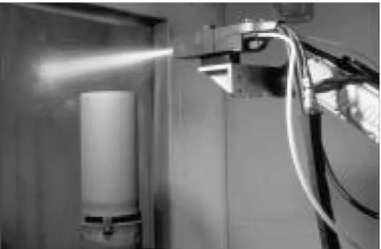
Coating Process: A thermal spray process, arc spraying,
for ductile metallic materials was selected to apply 200 mm (nominal) thick aluminum coatings on to 7075-T651 aluminium alloy substrates. Arc spraying uses an electric arc as a heat source to melt two consumable aluminum wires 1.6 mm in diameter. The melted droplets were propelled on to the substrate surface by atomization as illustrated in Figure 1. In this work, the selected atomizing gas was air. The aluminum coating was produced from four different commercial arc spray guns: Smart Arc from Sulzer Metco, BP 400 from Praxair, JP 9000 from Praxair and Thermion Precision Arc from Thermion Incorporated. The different coatings were evaluated in terms of their microstructure and fatigue properties.
Fatigue Testing
Constant amplitude fatigue tests were carried out at a fully reversed (R = -1) constant amplitude of ±225 MPa in accordance with ASTM 466-82 [17]. A frequency of 20 Hz was selected to avoid potential frequency induced heating with a sinusoidal loading wave form applied via a computer controlled MTS servo-hydraulic load frame. Testing was performed on coupons with each of the four coating types as
EFFECT OF DUCTILE THERMAL SPRAY COATINGS ON FATIGUE PERFORMANCE OF 7075-T651 ALUMINUM ALLOY 497
well as on coupons in the smooth and shot peened states prior to coating. All tests were performed in duplicate and failure was defined as the incidence of complete separation of the respective coupon halves.
Post-failure fractographic analysis was performed under a scanning electron microscope (SEM). Particular care was taken to identify the location of crack initiation sites, the path of crack propagation and any interfacial debonding phenomena.
RESULTS
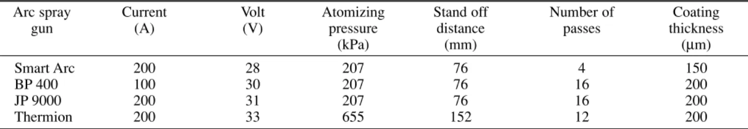
The coating process parameters are described in Table I for each processing gun. Figure 2 illustrates the cross-sectional
microstructures resulting from the successive accumulation of coating splat particles that form the lamellae type microstructure. The coating cross section was taken in the short transverse direction perpendicular to the scanning direction of the arc spray gun from the shoulder of the tested fatigue coupons.
Each of the commercial arc spray guns used in this study had a specific nozzle design and therefore different atomization results and microstructure for the same energy input. Among the four guns, the Thermion was the most distinct with its large atomization nozzle. Consequently, as this is an ongoing work, the focus is on results obtained using common parameters with attention given to the resulting specific lamellae in the microstructure, the coating/substrate Table I --Arc spray parameters
Arc spray Current Volt Atomizing Stand off Number of Coating
gun (A) (V) pressure distance passes thickness
(kPa) (mm) (mm)
Smart Arc 200 28 207 76 4 150
BP 400 100 30 207 76 16 200
JP 9000 200 31 207 76 16 200
Thermion 200 33 655 152 12 200
Fig. 2. Cross-section microstructure resulting from four arc sprayed guns: a) Smart Arc, b) BP 400, c) JP 9000 and d) Thermion.
b a
interface and the coating roughness produced by each gun. The effect of the porosity size, volume fraction and distri-bution will be addressed in the future using one arc spray gun with different process parameters, atomizing gases and surface preparations.
From the four microstructures, it is evident that the atomization made by these guns varied significantly. While the Smart Arc produces the smallest lamellae, the JP 9000 and Thermion guns produced coarser lamellae (Figure 2). It is important to note that larger lamellae are associated with more delamination, larger pores and coatings with less uniformity in thickness as described in Figures 2c and 2d.
Results from fatigue testing of all the coupons are shown in Figure 3. It can be seen that the shot peening pretreatment increased the fatigue resistance of polished coupons. Application of the coatings, however, subsequently led to a severe reduction in fatigue life whose magnitude exceeded the initial increases observed following shot peening. Fatigue lives for specimens with each of the four coatings were thus shorter than for the original polished specimens. Among the coated specimens, fatigue lives were greatest for coupons coated using Smart Arc parameters with cycles to failure diminishing from BP 400 to JP 9000 to Thermion, in decreasing order.
Table II shows the surface roughness of each coupon type measured using an interferometric profilometer (Wyko RS-2 from Wyko Industrial Services, Halesowen, UK). An adjustment for the cylindrical curvature of the specimens was applied in all cases. The two values of surface roughness given are Ra, the average roughness taken for 20 samples and
Rz, the average peak-to-valley height.
Characteristic initiation sites for polished and shot peened coupons, respectively are shown in Figures 4a and 4b. Failure in the polished specimens was generally characterized by a single initiation site located on the coupon surface. For the shot peened coupons, however, failure was characterized by initiation sites located away from the coupon surface, often at multiple sites.
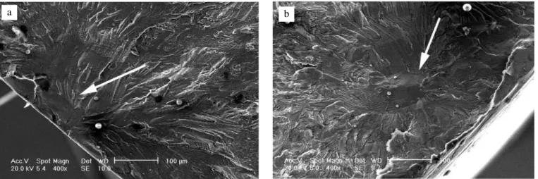
Typical crack initiation sites for the coated coupons are shown in Figure 5. In all cases, initiation occurred near the edge of the substrate at the interface with the coating. No sub-surface initiations were observed in the coated coupons. Multiple initiation sites were observed in some coupons; however, no apparent trend for this occurrence was evident (Table III).
Some delamination was observed at the interface between the coating and substrate (Figure 6), for the coating groups identified in Table III. The extent of damage at the interface appeared to correspond to the experimental fatigue lives (Figure 3). The most severe delamination was observed in coatings with low fatigue lives and are shown with arrows in Figures 6b to 6d; however, no evidence of delamination
Table II --Surface roughness of coupon types Coupon type Ra(mm) Rz(mm)
Mean Std dev Mean Std dev Polished 0.01 <0.01 0.11 0.02 Shot peened 1.80 0.35 19.2 4.10 Smart arc 19.8 3.55 194 55.9 BP 400 27.1 6.62 271 82.3 Thermion 29.2 13.2 241 97.0 JP 9000 29.7 11.4 266 101
Fig. 3. Fatigue lives of polished, shot peened and coated specimens. Fully reversed ±225 MPa constant amplitude loading; error bars represent one standard deviation, n = 2 for all groups.
Fig. 4. Crack initiation sites: a) on a polished specimen and b) on a shot peened specimen.
was observed in the coupons exhibiting the greatest fatigue resistance (e.g., Smart Arc coating shown in Figure 6a).
Evidence of crack propagation into both the substrate and the coating was observed in some groups. Figure 7 shows
the crack propagation pattern from a Thermion coupon indicating clear damage in both the substrate and coating that appears to emanate from an initiation site at the interface and propagated into both the coating and the substrate. Similar EFFECT OF DUCTILE THERMAL SPRAY COATINGS ON FATIGUE PERFORMANCE OF 7075-T651 ALUMINUM ALLOY 499
Fig. 5. Crack initiation sites for coated coupons by a) Smart Arc, b) BP 400, c) Thermion and d) JP 9000. The circle areas indicate the estimated location of initiation sites.
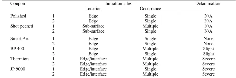
Table III --Characterization of initiation sites
Coupon Initiation sites Delamination
Location Occurrence
Polished 1 Edge Single N/A
2 Edge Single N/A
Shot peened 1 Sub-surface Multiple N/A
2 Sub-surface Single N/A
Smart Arc 1 Edge Single None
2 Edge Single None
BP 400 1 Edge Multiple Slight
2 Edge Single Slight
Thermion 1 Edge/interface Multiple Severe
2 Edge/interface Multiple Severe
JP 9000 1 Edge/interface Single Severe
2 Edge/interface Multiple Severe
a b
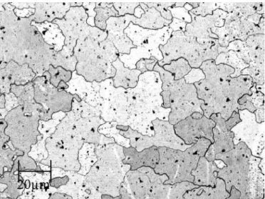
evidence indicative of crack initiation at the interface exists in all four groups. It should be noted that there was no evidence of cracks having propagated from the coating into the substrate. Figure 8 shows an optical micrograph of a sample taken from the center of a 7075-T651 Al alloy fatigue specimen.
The sample was etched with a Keller solution for micro-examination as shown in Figures 8 and 9. Figure 9 shows optical micrographs of each coating/substrate interface for the four arc spray guns. The optical micrographs of Figure 9 show no noticeable evolution in the grain structure of the substrate at the boundary of the coating with respect to the 7075-T651 alloy shown in Figure 8.
DISCUSSION
The improved fatigue performance observed following shot peening pretreatment was consistent with the widely accepted phenomenon of shot peening increasing the fatigue resistance of components. Such increases result from residual compressive stresses inhibiting the motion of dislocations, retarding or even preventing the initiation and growth of cracks [7,18,19]. The location of the initiation sites observed in the data presented in Table III also indicates the presence of residual compressive stresses near the surface with initiation occurring away from the surface regions affected by shot peening.
The change in initiation site from sub-surface to near surface of the substrate following application of the coatings
Fig. 6. Coating delamination in: a) Smart Arc, b) BP 400, c) Thermion and d) JP 9000 coupons.
Fig. 7. Crack propagation pattern in a Thermion coupon.
a b
indicates a shift in the residual stress state within the coupons. While the sub-surface initiations observed in the shot peened coupons are indicative of residual compressive stresses, the near surface initiation sites indicate that these pre-existing stresses were relieved during the coating process. Previous reports have proposed that heat flux resulting from the coating process may have a significant effect on the fatigue resistance of forged or heat treated substrates, particularly in cases where shot peening treatments have been applied prior to coating [5,20,21]. In the present study, the micrographs in Figure 9 show no noticeable evolution in the grain size or structure. The precipitates in the grains remain randomly dispersed and are not likely affected by the thermal spray process on to the coated fatigue samples with respect to the untreated 7075 Al alloy shown in Figure 8. It is important to note that arc spraying propelled liquid metal to the surface without the use of a flame that would add further heat into the substrate. Consequently, after arc spraying, the bulk temperature of the fatigue sample reached a temperature of about 65 ∞C which is far below the 150 to 300 ∞C reached EFFECT OF DUCTILE THERMAL SPRAY COATINGS ON FATIGUE PERFORMANCE OF 7075-T651 ALUMINUM ALLOY 501
Fig. 8. Micrograph of 7075-T651 short transverse for the as-received extruded rod.
Fig. 9. Optical micrograph of the coating/substrate interface for the four arc sprayed guns: a) Smart Arc b) BP 400 c) JP 9000 and d) Thermion.
a b
after high velocity oxy-fuel (HVOF) deposition. Hence, the drastic decrease in the fatigue life of the coated 7075 Al alloy cannot be justified by heat affected substrates. Considering the atomized Al particle temperature during arc spraying reaches a temperature above the Al melting point, the heat transported by the sprayed particle could possibly perform a localized micro-annealing on the surface boundary during spraying. Gougeon et al. [22] observed that thermal sprayed
particles flatten and solidify on a substrate in less than 20 ms. Such a short dwell time provides an extremely brief heat flux to the substrate surface and therefore a limited exposure in time to elevated temperatures during spraying. Therefore, this could explain the absence of noticeable microstructure evolution in Figure 9.
Although the localized surface temperature measurement during spraying is beyond the scope of this paper, further work is in progress to define the local temperature reached on the coating surface behind the arc jet and under the interface. Moreover, this localized temperature evaluation will be performed for different process parameters during spraying with the corresponding near surface microstructure of the substrate combined to the fatigue response.
While changes in substrate residual stress induced by the heat flux during coating may account for general reductions in fatigue life between shot peened and coated coupons, the largely identical nature of the coatings – and the techniques used to apply them – suggest that an alternative mechanism is responsible for the differences between the respective coating groups. Residual stresses induced by the presence of the coating itself (note that this is separate from the heat generated during coating) are often cited as a
potential cause of altered substrate fatigue behaviour [5,12]. However in cases where coating thickness and composition are largely identical, the magnitude of induced residual stresses does not vary significantly, particularly in the substrate; analysis using the model of Tsui and Clyne [23,24] confirms this assertion for the present case.
Comparison of the results presented in Tables II and III with the fatigue lives of each coating group (Figure 3) revealed that coatings producing the lowest fatigue lives are characterized by both greater surface roughness and a higher incidence of delamination. To evaluate the contribution of each of these two phenomena to the observed reduction in fatigue life, it is necessary to consider the mechanisms underlying each.
Surface roughness in a coating produces local areas of stress concentration along the surface of a coupon as illustrated schematically in Figure 10. These local stress concentrations can, in some cases, induce the formation of fatigue cracks within the coating which then propagate toward the interface.
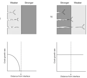
The behaviour of cracks propagating toward bimaterial interfaces has been characterized in a series of experiments by Suresh and Sugimura [9,25-27]. The results of these studies show that the ability of a given crack to penetrate a bimaterial interface is dependent on the strength of the material in which
it is propagating where the term ‘strength’ is defined by the strain hardening response and ultimate tensile strength [10,25]. In cases where a crack propagating in a lower strength material approaches an interface with a higher strength material, the plastic slip mechanisms acting ahead of the crack tip are restricted by the presence of the stronger material, subsequently leading to crack arrest (Figure 11a). In the inverse case (Figure 11b), a crack propagating from the stronger material towards the weaker one, the crack proceeds unimpeded across the interface and continues to propagate in the weaker material [25]. For the coatings observed in the present study, high strength Al 7075-T651 substrate and the
Fig. 11. Behaviour of cracks propagating towards a bimaterial interface a) from a weaker material towards a stronger material and b) from a stronger material towards a weaker material.
Fig. 10. Zones of local stress concentration along the surface of a rough coating.
comparatively weak coatings form an analogous case to that shown in Figure 11a.
The absence of cracks having initiated in the coating and subsequently propagated into the substrate is consistent with this model and furthermore corresponds to the observations that the initiation sites for the critical fatigue cracks were located in the substrate in all cases. Therefore, any cracks originating from the near surface zones of stress concen-tration within the coating were unlikely to have penetrated the substrate and thus had little effect on the fatigue life of the coupon.
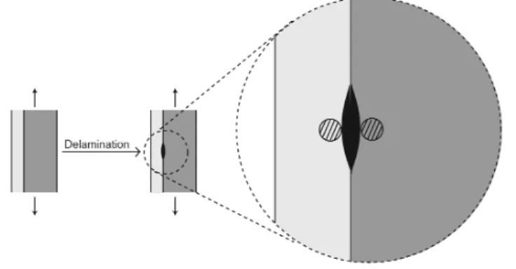
Interfacial debonding (delamination) is thought to have an effect on substrate fatigue resistance [12], but this phenomenon has been reported predominantly in systems with brittle coatings [5,10,28]. Debonding in such systems has been reported to accompany the propagation of cracks from coating to substrate and has been reported to lead to the initiation of fatigue cracks into the substrate [28,29]. While a more detailed analytical treatment of the mechanisms leading to delamination induced crack initiation is clearly warranted, Figure 12 shows a simple model based on stress concen-trations surrounding a zone of delamination. Treating the debonded area as an intrinsic flaw, stress concentrations on both the coating and substrate sides act as potential sites of fatigue crack initiation. This mechanism presents a plausible explanation for initiation sites such as that shown in Figure 6 and the other observed instances of propagation both into the substrate and into the coating. Increased severity (and number) of these delamination induced stress concentrations would account for the observed differences in fatigue life with the greatest fatigue resistance exhibited by the coupons showing no debonding (Smart Arc) and the poorest fatigue resistance exhibited by coupons that undergo the most severe debonding (Thermion). With the absence of microgaps at the coating/substrate interface even after the fatigue testing and the lowest coating roughness, the Smart Arc equipment provided the best fatigue behaviour among the aluminum coated 7075-T651 Al alloy specimens.
However, a major improvement in fatigue performance is needed for these arc sprayed coatings to be viable in fatigue sensitive applications. Indeed, the fatigue life should
preferably increase by at least an order of magnitude for the Smart Arc coating and by even more for the other guns. On the basis of the observations made in this study, the following issues need to be addressed for the required improvement: 1. minimization of the heat flux into the substrate during the coating process and
2. optimization of the bond strength between coating and substrate (to avoid debonding) to reduce interface stress concentrations.
Controlling spray parameters to reduce the heat input may allow for the preservation of some of the residual compressive stresses induced by shot peening, while concur-rently avoiding any changes in substrate microstructure at the surface boundary or residual stresses induced by tempering. Moreover, optimization of the bond strength between coating and substrate may reduce or eliminate the detrimental effects of coating surface roughness, as even cracks originating at roughness induced stress concentrations would fail to penetrate the substrate as a result of the mechanisms described above. Furthermore, avoiding debonding would avoid stress concentrations forming at the interface, thereby maximizing the resistance of the substrate to fatigue damage.
Process techniques which optimize bond strength, reduce interface microgaps and improve fatigue performance are currently under investigation by the authors; the preliminary results are encouraging.
CONCLUSIONS
The fatigue behaviour of Al 7075-T651 with ductile thermal spray coatings has been characterized. Thermally induced changes in the residual stress state and delamination induced stress concentrations in the substrate have been identified as the most likely sources of reduction in fatigue life observed for the coated specimen since no microstructural change with respect to the substrate was perceptible. With the absence of microgaps at the coating/substrate interface, even after the fatigue tests and with the lowest coating roughness, the Smart Arc equipment provided the best fatigue behaviour for the Al coated 7075-T651 Al alloy in this study.
REFERENCES
1. N.P. Padture, M. Gell and E.H. Jordan, “Materials Science - Thermal Barrier Coatings for Gas-Turbine Engine Applications”, Science, 2002, vol. 296(5566), pp. 280-284.
2. J.E. Gray and B. Luan, “Protective Coatings on Magnesium and its Alloys - A Critical Review”, Journal of Alloys and Compounds, 2002, vol. 336(1-2), pp. 88-113.
3. P.A. Dearnley, “A Review of Metallic, Ceramic and Surface-Treated Metals Used for Bearing Surfaces in Human Joint Replacements”, Proceedings of the Institution of Mechanical Engineers, Part H-Journal of Engineering in Medicine, 1999, vol. 213(H2), pp. 107-135. 4. S. Stewart and R. Ahmed, “Rolling Contact Fatigue of Surface Coatings
- A Review”, Wear, 2002, vol. 253(11-12), pp. 1132-1144.
5. A.K. Lynn and D.L. DuQuesnay, “Hydroxyapatite-Coated Ti-6Al-4V Part 1: The Effect of Coating Thickness on Mechanical Fatigue Behaviour”, Biomaterials, 2002, vol. 23(9), pp. 1937-1946.
EFFECT OF DUCTILE THERMAL SPRAY COATINGS ON FATIGUE PERFORMANCE OF 7075-T651 ALUMINUM ALLOY 503
6. K. Padilla, A. Velasquez, J.A. Berrios and E.S.P. Cabrera, “Fatigue Behavior of a 4140 Steel Coated with a NiMoAl Deposit Applied by HVOF Thermal Spray”, Surface & Coatings Technology, 2002, vol. 150(2-3), pp. 151-162.
7. A.W. Eberhardt, B.S. Kin, D. Rigney, G.L. Kutner and C.R. Harte, “Effects of Precoating Surface Treatments on Fatigue of Ti-6Al- 4V”, Journal of Applied Biomaterials, 1995, vol. 6(3), pp. 171-174. 8. R.T.R. McGrann, D.J. Greving, J.R. Shadley, E.F. Rybicki, T.L.
Kruecke and B.E. Bodger, “The Effect of Coating Residual Stress on the Fatigue Life of Thermal Spray-Coated Steel and Aluminum”, Surface & Coatings Technology, 1998, vol. 109(1-3). pp. 59-64. 9. Y. Sugimura and S. Suresh, “Fatigue of Coated Materials”, 1993 ASME
Winter Annual Meeting, 1993, New York, American Society of Mechanical Engineers.
10. S. Suresh, Y. Sugimura and T. Ogawa, “Fatigue Cracking in Materials with Brittle Surface-Coatings”, Scripta Metallurgica et Materialia, 1993, vol. 29(2), pp. 237-242.
11. M.C. Shaw, D.B. Marshall, B.J. Dalgleish, M.S. Dadkhah, M.Y. He and A.G. Evans, “Fatigue-Crack Growth and Stress Redistribution at Interfaces”, Acta Metallurgica et Materialia, 1994, vol. 42(12), pp. 4091-4099.
12. R.L. Holtz and K. Sadananda, “Fatigue Behaviour of Nanostructured and Conventional Coatings”, Thermal Spray Processing of Nanoscale Materials II, 1999, C.C. Berndt, ed., New York, United Engineering Foundation, pp. 30-32.
13. R.T.R. McGrann, D.J. Greving, J.R. Shadley, E.F. Rybicki, B.E. Bodger and D.A. Somerville, “The Effect of Residual Stress in HVOF Tungsten Carbide Coatings on the Fatigue Life in Bending of Thermal Spray Coated Aluminum”, Journal of Thermal Spray Technology, 1998, vol. 7(4), pp. 546-552.
14. J.A. Berrios, D.G. Teer and E.S. Puchi-Cabrera, “Fatigue Properties of a 316L Stainless Steel Coated with Different TiNx Deposits”, Surface & Coatings Technology, 2001, vol. 148(2-3), pp. 179-190.
15. S.Y. Zhang and W.G. Zhu, “TiN Coating of Tool Steels - A Review”, Journal of Materials Processing Technology, 1993, vol. 39(1-2), pp. 165-177.
16. A.K. Lynn and D.L. DuQuesnay. “Hydroxyapatite-Coated Ti-6Al-4V Part 2: The Effects of Post-Deposition Heat Treatment at Low Temperatures”, Biomaterials, 2002, vol. 23(9), pp. 1947-1953. 17. ASTM E 366-82: Standard Practice for Conducting Constant
Amplitude Axial Fatigue Tests of Metallic Materials, Annual Book of ASTM Standards, 1998, Materials Park, OH, U.S.A., American Society for Testing and Materials; 1998. pp. 465-469.
18. K. Tanaka and Y. Akiniwa, “Fatigue Crack Propagation Behaviour Derived from S-N Data in Very High Cycle Regime”, Fatigue & Fracture of Engineering Materials & Structures, 2002, vol. 25(8-9), pp. 775-784.
19. A. Turnbull, E.R. de los Rios, R.B. Tait, C. Laurant and J.S. Boabaid, “Improving the Fatigue Crack Resistance of Waspaloy by Shot Peening”, Fatigue & Fracture of Engineering Materials & Structures, 1998, vol. 21(12), pp. 1513-1524.
20. S.L. Evans and P.J. Gregson, “The Effect of a Plasma-Sprayed Hydroxyapatite Coating on the Fatigue Properties of Ti-6Al-4V”, Materials Letters, 1993, vol. 16, pp. 270-274.
21. D.J. Forrest, J.C. Shelton and P.J. Gregson, “Fatigue Failure in a Plasma Sprayed Hydroxyapatite Coated Titanium Alloy”, Fifth World Biomaterials Congress, 1996, Toronto, University of Toronto Press, p. 324.
22. P. Gougeon and C. Moreau, “Simultaneous Independent Measurement of Splat Diameter and Cooking Time during Impact on a Substrate of Plasma-Sprayed Molybdenum Particles”, Journal of Thermal Spray Technology”, 2001, vol. 10(1).
23. Y.T. Tsui and T.W. Clyne, “An Analytical Model for Predicting Residual Stresses in Progressively Deposited Coatings, Part 1: Planar Geometry”, Thin Solid Films, 1997, vol. 306(23-33).
24. Y.T. Tsui and T.W. Clyne, “An Analytical Model for Predicting Residual Stresses in Progressively Deposited Coatings, Part 2: Cylindrical Geometry”, Thin Solid Films, 1997, vol. 306, pp. 34-51. 25. S. Suresh, Y. Sugimura and E.K. Tschegg, “The Growth of a Fatigue
Crack Approaching a Perpendicularly-Oriented, Bimaterial Interface”, Scripta Metallurgica et Materialia, 1992, vol. 27(9), pp. 1189-1194. 26. Y. Sugimura, P.G. Lim, C.F. Shih and S. Suresh, “Fracture Normal to a
Bimaterial Interface - Effects of Plasticity on Crack-Tip Shielding and Amplification”, Acta Metallurgica et Materialia, 1995, vol. 43(3), pp. 1157-1169.
27. Y. Sugimura, L. Grondin and S. Suresh, “Fatigue-Crack Growth at Arbitrary Angles to Bimaterial Interfaces”, Scripta Metallurgica et Materialia, 1995, vol. 33(12), pp. 2007-2012.
28. T. Ogawa, K. Tokaji, J.U. Hwang, T. Ejima, Y. Kobayashi and Y. Harada, “Fatigue Strength and Fracture Mechanisms of WC Cermet-Sprayed Steel”, Materials Science Research International, 1996, vol. 2(4), pp. 267-272.
29. J.U. Hwang, K. Tokaji and T. Ogawa, “Fatigue Strength and Fracture Mechanisms of Ceramic Thermal Spray Coatings”, Annual Meeting of JSME, Mechanics and Materials Division, 1992, Tokyo, JSME; 1993, pp. 1663-1668.