Publisher’s version / Version de l'éditeur:
Vous avez des questions? Nous pouvons vous aider. Pour communiquer directement avec un auteur, consultez la
première page de la revue dans laquelle son article a été publié afin de trouver ses coordonnées. Si vous n’arrivez
Questions? Contact the NRC Publications Archive team at
PublicationsArchive-ArchivesPublications@nrc-cnrc.gc.ca. If you wish to email the authors directly, please see the first page of the publication for their contact information.
https://publications-cnrc.canada.ca/fra/droits
L’accès à ce site Web et l’utilisation de son contenu sont assujettis aux conditions présentées dans le site LISEZ CES CONDITIONS ATTENTIVEMENT AVANT D’UTILISER CE SITE WEB.
Client Report (National Research Council of Canada. Construction), 2014-12-31
READ THESE TERMS AND CONDITIONS CAREFULLY BEFORE USING THIS WEBSITE.
https://nrc-publications.canada.ca/eng/copyright
NRC Publications Archive Record / Notice des Archives des publications du CNRC : https://nrc-publications.canada.ca/eng/view/object/?id=888ff458-c0cc-4706-a85d-b5dcc3879be3 https://publications-cnrc.canada.ca/fra/voir/objet/?id=888ff458-c0cc-4706-a85d-b5dcc3879be3
NRC Publications Archive
Archives des publications du CNRC
For the publisher’s version, please access the DOI link below./ Pour consulter la version de l’éditeur, utilisez le lien DOI ci-dessous.
https://doi.org/10.4224/21274559
Access and use of this website and the material on it are subject to the Terms and Conditions set forth at
Solutions for mid-rise wood construction: full-scale standard fire test
for exterior wall assembly using a simulated cross-laminated timber
wall assembly with gypsum sheathing: Test EXTW-2: report to
Research Consortium for Wood and Wood-Hybrid Mid-Rise Buildings
NATIONAL RESEARCH COUNCIL CANADA
REPORT TO RESEARCH CONSORTIUM
FOR WOOD AND WOOD-HYBRID
MID-RISE BUILDINGS
Solutions for Mid-Rise Wood Construction
:
Full-scale Standard Fire Test for Exterior
Wall Assembly using a Simulated
Cross-Laminated Timber Wall Assembly with
Gypsum Sheathing (Test EXTW-2)
CLIENT REPORT: A1-100035-01.5
December 31, 2014
REPORT TO RESEARCH CONSORTIUM FOR WOOD AND
WOOD-HYBRID MID-RISE BUILDINGS
Solutions for Mid-Rise Wood Construction:
Full-scale Standard Fire Test for Exterior Wall Assembly using a
Simulated Cross-Laminated Timber Wall Assembly with Gypsum
Sheathing (Test ExtW-2)
E. Gibbs, B.C. Taber, G.D. Lougheed, J.Z. Su and N. Bénichou
Report No. A1-100035-01.5 Report date: December 31, 2014 Contract No. B-7000 (A1-100035) Prepared for Canadian Wood Council
FPInnovations
Régie du bâtiment du Québec
HER MAJESTY THE QUEEN IN RIGHT OF ONTARIO as represented by the Minister of Municipal Affairs and Housing
24 pages
This report may not be reproduced in whole or in part without the written consent of both the client and the National Research Council of Canada.
TABLE OF CONTENTS
Contents
1 Introduction ...1
2 Test Facility...3
3 Description of Test Wall Assembly ...5
4 Instrumentation ...8
5 Atmospheric Conditions ...9
6 Test Procedure...9
7 Visual Observations ...9
8 Results...10
9 Performance of the Wall Assembly...19
10 Remarks...23
11 Acknowledgments...23
12 References...24
LIST OF FIGURES Figure 1. Test Facility (front view)...4
Figure 2. Test Facility (side view). ...4
Figure 3 . Construction Detail. ...7
Figure 4. Wall System under Construction. ...8
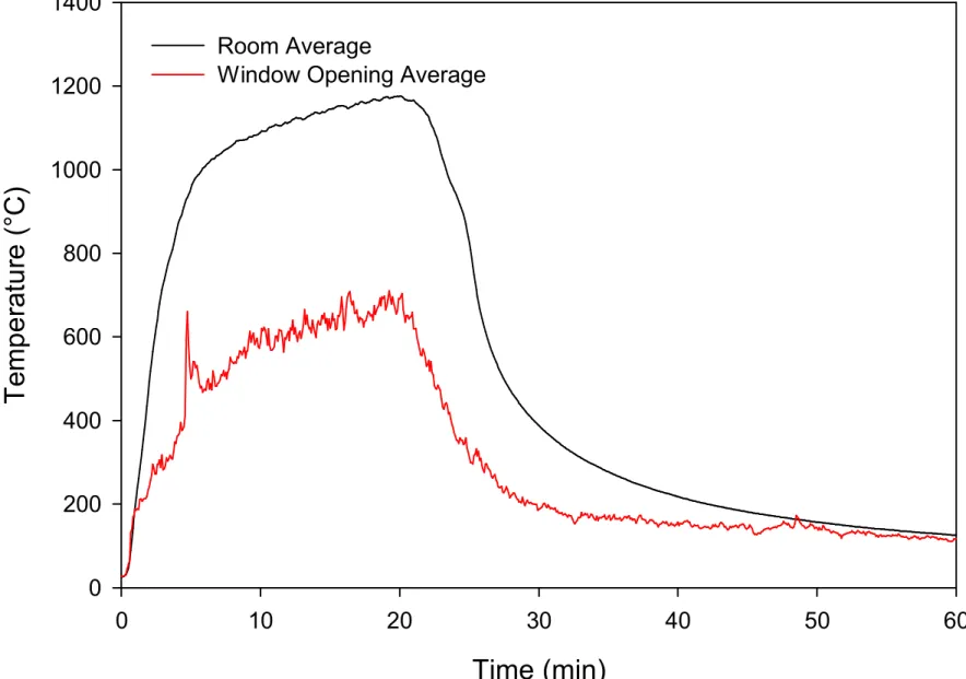
Figure 5. Average Room and Window OpeningTemperatures...12
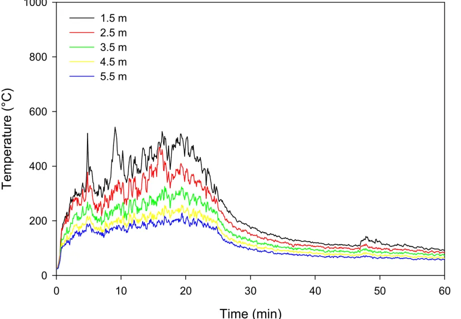
Figure 6. Temperatures on Surface of Wall. ...13
Figure 7. Temperatures Inside the Wall Cavity. ...14
Figure 8 . Temperatures on Surface of 15.9 mm Type X Gypsum Board...15
Figure 9. Temperatures at Top of Wall. ...16
Figure 10. Heat Flux on Wall. ...17
Figure 11. Heat Flux at Mast. ...18
Figure 12. Wall Sample During the Fire Exposure...21
Figure 13. Wall Sample after Fire Exposure. ...22
LIST OF TABLES Table 1. Average Values of Heat Flux at Target Mast. ...19
SOLUTIONS FOR MID-RISE WOOD CONSTRUCTION:
FULL-SCALE STANDARD FIRE TEST FOR EXTERIOR WALL ASSEMBLY USING A SIMULATED CROSS-LAMINATED TIMBER WALL ASSEMBLY WITH GYPSUM
SHEATHING TEST EXTW-2
E. Gibbs, B.C. Taber, G.D. Lougheed, J.Z. Su and N. Bénichou
1 INTRODUCTION
The acceptable solutions provided in the 2010 National Building Code (NBC) Division B [1] limits the use of combustible (wood) construction based on building height. For example, for Group C (Residential), Group D (Business and Personal Services) and Group E (Mercantile) occupancies, combustible construction can be used up to 4 storeys, and up to 2 storeys for Group A – Division 2 (Assembly) occupancies. In addition to the building height limitation, there are also building area limitations in the 2010 NBC for the use of combustible construction for these occupancies. For buildings that exceed the height and area requirements for combustible construction, the
prescriptive requirements in the 2010 NBC require that noncombustible construction be used for the primary structural elements.
The prescriptive construction requirements for fire safety and protection of buildings, which are dependent upon the building size and occupancy type, are provided in Subsection 3.2.2 of the 2010 NBC. This includes the identification of the buildings for which noncombustible construction is required. The intent of the prescriptive
requirements for noncombustible construction as they relate to the NBC fire safety/fire protection of building objectives is “to limit the probability that combustible construction
materials within a storey of a building will be involved in a fire, which could lead to the growth of fire, which could lead to the spread of fire within the storey during the time required to achieve occupant safety and for emergency responders to perform their duties, which could lead to harm to persons/damage to the building”.
The 2010 NBC defines noncombustible construction as “that type of construction in
which a degree of fire safety is attained by use of noncombustible construction materials for structural members and other building assemblies” [1]. Article 3.1.5.1 requires that a
building or part of a building required to be of noncombustible construction be
constructed using noncombustible materials. The intent of this requirement, as it relates to the NBC fire safety/fire protection of building objectives, is “to limit the probability that
construction materials will contribute to the growth and spread of fire, which would lead to harm to persons/damage to the building”.
The NBC does permit, as exceptions, an extensive use of combustible materials in buildings otherwise required to have their primary structural elements to be of noncombustible construction. The allowed materials and associated limitations are primarily provided in Articles 3.1.5.2 to 3.1.5.21. Generally, the combustible elements permitted relate to interior finishes, gypsum board, combustible roofing materials, combustible plumbing fixtures, cabling, protected insulation, flooring, combustible glazing, combustible cladding systems, non-loadbearing framing elements in partitions, stairs in dwellings, and trim and millwork, among others.
Divisions B of the NBC (the “acceptable solutions” portion of the Code) generally does not permit combustible materials to be used for the primary structural elements in buildings required to be of noncombustible construction. In the Scoping Study [2] for mid-rise and hybrid buildings, it was suggested that an alternative solution using wood construction may be developed to meet the intent of the prescriptive “noncombustibility” requirement for mid-rise (and taller) buildings. As one approach, encapsulation materials could be used to protect the combustible (wood) structural materials for a period of time in order to delay the effects of the fire on the combustible structural elements, including delay of ignition. In delaying ignition, any effects of the combustion of the combustible structural elements on the fire severity can be delayed. In some cases, and depending upon the amount of encapsulating material used (e.g. number of layers), ignition of the elements might be avoided completely. This scenario would primarily depend upon the fire event and the actual fire performance of the encapsulating materials used. A
research project, Wood and Wood-Hybrid Midrise Buildings, was undertaken to develop information to be used as the basis for alternative/acceptable solutions for mid-rise construction using wood structural elements.
In Article 3.1.5.5, the NBC allows the use of combustible components for non-loadbearing exterior walls to be used in a building required to be of noncombustible construction provided:
a) the building is
i. not more than 3 storeys in height, or ii. sprinklered throughout,
b) the interior surfaces of the wall assembly are protected by a thermal barrier conforming to Sentence 3.1.5.12.(3), and
c) the wall assembly satisfies the criteria of Sentence 3.1.5.5.(3) and 3.1.5.5.(4) when subjected to testing in conformance with CAN/ULC-S134 Fire Test of
Exterior Wall Assemblies [3].
Since the introduction of the requirements for the use of combustible components for non-loadbearing exterior walls in noncombustible construction, a number of proprietary cladding systems have been developed that meet the requirements in the NBC when tested using CAN/ULC-S134. However, one assumption in this testing is that the non-loadbearing exterior wall assemblies will be used in conjunction with an exterior wall system constructed using noncombustible structural elements either as infill or panel type walls between structural elements or attached directly to a loadbearing
noncombustible structural system (see Appendix Note A-3.1.5.5.(1) of the 2010 NBC). During the development of the CAN/ULC-S134 test method, three assemblies using lightweight wood frame construction met the criteria in the 2010 NBC for
non-loadbearing exterior walls [4, 5]:
1. Assembly 3.1. - Vinyl siding on gypsum sheathing on glass-fibre-insulated untreated (non-fire-retardant-treated) wood frame wall;
2. Assembly 3.3. - 12.7 mm fire-retardant-treated plywood on untreated (non-fire-retardant-treated) wood studs, with phenolic foam insulation in cavities; and 3. Assembly 3.4. - Aluminum sheet (0.75 mm) on fire-retardant-treated wood studs,
The results of the original three tests can currently provide the basis for developing generic alternative solutions for exterior wall assemblies for use in mid-rise buildings using lightweight wood frame construction. However, generic alternative solutions based on these tests would be limited by the materials tested, including the insulation types used in the original tests.
One of the tasks in the project, Wood and Wood-Hybrid Midrise Buildings, was to develop further information and data for use in developing generic exterior wall systems for use in mid-rise buildings using either lightweight wood frame or cross-laminated timber as the structural elements. This report describes a standard full-scale exterior wall fire test conducted on May 22, 2012 on a simulated cross-laminated timber (CLT) wall assembly with an attached insulated lightweight wood frame assembly protected using gypsum sheathing. The test was conducted in accordance with CAN/ULC-S134 [3].
2 TEST FACILITY
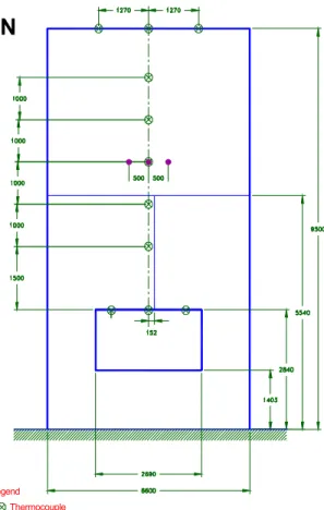
The test was conducted using the exterior wall fire test apparatus as described in CAN/ULC-S134 (see Figure 1 and Figure 2) located in the Burn Hall of the NRC Fire Laboratory, Almonte, Ontario.
The burn room portion of the apparatus consisted of a reinforced concrete floor, concrete block walls and a precast concrete panel ceiling. The walls and ceiling were covered on the room side with 25 mm thick ceramic fibre insulation. The floor was covered with 57 mm thick fired clay paving stones. The inside dimensions of the burn room were 5.95 m wide, 4.4 m deep and 2.75 m high.
The fuel source in the burn room consisted of four 3.8 m long linear propane burners spaced equally along the width of the room and designed to provide a fire exposure equivalent to uniformly-distributed wood cribs of kiln-dried pine (with pieces 38 mm x 89 mm), having a total mass of approximately 675 kg. The burners were mounted 0.6 m above the surface of the paving stones.
Legend Thermocouple
Heat flux meter All dimensions in mm
Figure 1. Test Facility (front view).
Figure 2. Test Facility (side view).
4400 2750 3000 1300 2400 1300 1300 Mast Wall Sample 2100
N
3 DESCRIPTION OF TEST WALL ASSEMBLY
The wall assembly simulated an exterior CLT wall with attached non-loadbearing insulated lightweight wood framing protected using gypsum sheathing. The wall
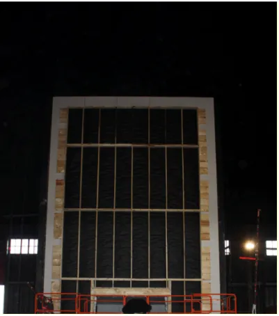
assembly was installed over 15.9 mm thick Type X gypsum board that formed part of the test facility. Drawings for the wall assembly are shown in Figure 3 and a photograph for the wall assembly under construction is shown in Figure 4.
The CLT portion of the wall assembly was simulated using 38 mm x 235 mm lumber laid flat and attached horizontally to the test facility with its wider side against the test
facility’s concrete block wall. The wall of the test facility was covered with the lumber to a width of approximately 5 m and a height of 9.9 m.
CLT wall systems can be much thicker than the simulated system used. However, a thickness of 38 mm was considered adequate for this testing because if, during the test, there was sufficient burning of the lumber to char through the 38 mm thickness provided, it is very likely that the wall system tested would not meet the requirements in 3.1.5.5. of the 2010 NBC anyway, and therefore any additional thickness of wood would be
redundant.
A water resistant barrier (WRB) was attached to the simulated CLT wall. This material was paper impregnated with asphalt. This type of WRB (identified as WRB-1 in
Reference [6]) was selected for use in the full-scale exterior wall assembly tests based on the results of cone calorimeter tests, which indicated that it ignited earlier and had a higher peak heat release rate and total heat output than a thermoplastic polyolefin (TPO) WRB.
An insulated wall sections were attached to the simulated CLT wall. Wall sections were constructed using 2 x 6 studs spaced at 600 mm on center (o.c.). The studs were 38 mm x 140 mm x 2400 mm long. The wall sections included a single base plate and a single top plate constructed using 38 mm x 140 mm x 2400 mm lumber.
Gypsum sheathing (12.7 mm x 1.2 m x 2.4 m panels) was used as the exterior surface of the wall assembly. The gypsum sheathing complied with CAN/CSA-A82-27-M91 [7]. The material was combustible, had a surface flame-spread rating of 20, and a smoke developed classification of 0. The gypsum sheathing was attached using 32 mm long coarse thread drywall screws at 200 mm spacing.
The cavity spaces formed by the wood studs were filled to the 140 mm depth using extruded polystyrene (XPS) foam insulation panels. Two panels with a thickness of approximately 50 mm and one with a thickness of approximately 39 mm were used to provide the required thickness. The sides of the panels were trimmed to provide the width needed to fit into the cavity space.
The XPS foam insulation used in the test assembly was selected based on cone
calorimeter tests that showed that XPS rigid foam insulation had higher heat output than expanded polystyrene (EPS) rigid foam insulation [6]. Of the three XPS rigid foam insulation products tested, the product identified as G-XPS in Reference 6 had the highest heat output and was used in the full-scale test.
Although an XPS foam insulation was used in the test assembly, it was assumed that, if the assembly using an XPS foam insulation met the requirements in 3.1.5.5. of the 2010 NBC for exterior wall systems, exterior wall assemblies insulated using EPS rigid foam insulation panels or non-combustible mineral fibre insulation would also meet the requirements.
The bottom wall section included an opening that was the same size as the window opening in the test facility. Standard framing for windows was used with double studs used on either side of the window opening and a double header using 38 mm x 235 mm lumber was installed above the window opening (Figure 3).
Metal flashing (approximately 25 mm by 25 mm) was located at the outer edge of the window opening. The flashing was fastened to the assembly inside the window opening. The edges of the wall assembly at the window opening and the metal flashing were covered with 25 mm thick ceramic fibre insulation. The metal flashing and ceramic fibre insulation are typically used for CAN/ULC-S134 test assemblies to limit flame
penetration at the edges of the test wall assembly.
The full test specimen was 9.9 m high and approximately 5.0 m wide, with a window opening 2.5 m wide and 1.45 m high. The wall assembly extended 7 m above the window opening in the test facility. It conformed to the height and width requirements for CAN/ULC-S134 [3].
A horizontal joint between gypsum sheathing panels was located 3.0 m above the window opening. This complies with the requirement in CAN/ULC-S134 [3] that a horizontal joint is located 2.7 ± 0.3 m above the window opening in the wall assembly. Additional horizontal joints were located at the 0.6 m and 5.4 m heights.
The test assembly had a vertical joint above the window opening on the centerline of the assembly. It also had vertical joints 1.2 m to either side of the centerline of the assembly. The test assembly simulated a structural exterior wall system. However, no loads were applied to the wall. The objective of the test was to evaluate the performance of the assembly for exterior fire spread. If, in practice, the exterior wall assembly required a fire-resistance rating as well, it would need to be evaluated using CAN/ULC-S101 [8]. The construction materials of the test wall assembly proceeding outward from the concrete block wall of the test facility were as follows:
1. 15.9 mm thick Type X gypsum board;
2. CLT wall simulated using 38 mm x 235 mm lumber laid flat and installed horizontally on the test facility;
3. Lightweight wood framing and XPS foam insulation; and, 4. 12.7 mm thick gypsum sheathing.
An exterior cladding system was not included in the test assembly. It was assumed that a noncombustible exterior cladding would provide additional protection for the wall assembly and, therefore, if the wall assembly met the requirements in Article 3.1.5.5. of the 2010 NBC without an exterior cladding, it would also meet the requirements with a noncombustible cladding. .
Wall Installation # 2 Figure 3 . Construction Detail.
Top of wall 7 m above window opening
Horizontal joint 3 m above window opening
Studs at 600 mm o.c. Single top plate Single base plate
Double 38 x 235 mm header Simulated CLT 38 mm x 235 mm lumber Ceramic fibre insulation 3000 mm 7000 mm
Figure 4. Wall System under Construction. 4 INSTRUMENTATION
Room Temperatures – The burn room air temperature was monitored by six Type K thermocouples, enclosed in 6 mm (outside diameter) Inconel sheaths. The
thermocouples were introduced through the side walls with the measuring tips 0.6 m from the inner surface of the wall. All room thermocouples were located on the vertical centre lines of the side walls.
Window Opening Temperatures – The temperature of the flames issuing from the
window opening was measured with three Type K, bare-beaded thermocouples installed 0.15 m below the top of the window opening, on the vertical centre line of the window opening and 0.4 m from the sides of the window opening (see Figure 1).
Wall Temperatures – The wall temperatures were monitored using Type K bare-beaded thermocouples on the vertical centre line of the wall. They were located at five levels above the top of the window opeing at 1.0 m intervals, starting at 1.5 m above the window opening (see Figure 1). Three thermocouples were used at each level, one on the exterior surface of the wall assembly, the second behind the XPS foam insulation in the cavity (between the XPS foam insulation and the WRB) and the third on the surface of the 15.9 mm Type X gypsum board at the interface with the wood used to simulate the CLT.
The temperature of the fire plume at the top of the test assembly was monitored by three Type K bare-beaded thermocouples located 0.1 m out from the exterior surface of the wall, one on the centre line of the wall, and the other two and the other two at a distance of 1.3 m to either side of the centre line of the wall (see Figure 1).
Heat Flow – The total heat flux to the wall above the window opening was monitored by three water-cooled heat flux meters (Medtherm Corp. Series 64) installed in the test wall, 3.5 m above the top of the window opening, one on the centre line of the wall and one on each side, 0.5 m from the centre line (see Figure 1).
Radiant heat emitting from the fire was also monitored by heat flux meters (Medtherm Corp. Series 64) installed on a mast (Figure 2), placed 3.0 m from the test wall opposite to the centre line of the wall. The heat flux meters were located at distances of 2.1 m, 3.4 m, 4.7 m and 6.0 m above the level of the burn room floor. An additional heat flux meter was installed on the mast at the 4.0 m height and 2.4 m from the face of the wall. Propane – The propane gas flow rate to the burners was monitored with a mass flow meter.
Visual Records – Video records of the front and side views were made during the test and digital photos were taken before, during and after the test.
Data Acquisition – All thermocouples, as well as the heat flux meters, were connected to a data acquisition system and readings were recorded at 5 s intervals.
5 ATMOSPHERIC CONDITIONS
At the time of the test, the ambient temperature in the Burn Hall was 20.4°C and the relative humidity was 81%.
6 TEST PROCEDURE
The test procedure was in accordance with CAN/ULC-S134-13 [3]. The pilot burners were lit prior to the commencement of the test. Gas flow to the burners was manually adjusted to follow the prescribed heat input required by the standard.
7 VISUAL OBSERVATIONS
(min:sec)
0:00 Ignition of burners
2:00 Flames are exiting the room
4:40 Paper has flashed behind the window fire plume 4:52 Flames are reaching 1.5 to 2.0 m
5:00 Steady state gas flow 7:51 Flame height is 2.0 to 2.5 m
12:34 Crackling is heard
13:25 Flames at the top of the window opening are growing and are more consistent 15:34 No change
15:57 Fire is burning slightly off center (towards the north)
16:11 Flames are forming on the left vertical edge of the window opening 17:33 Flashing is buckling at the upper left corner of the window opening 20:00 Gas flow being reduced
20:57 Crackling sounds are heard
22:34 Glowing embers seen at the top of the window opening 23:30 Embers popping from the upper left corner
24:19 Damage to the wall extending to 3.0 m, small cracks in the gypsum sheathing below 0.5 m
25:00 Gas is turned off
25:57 Flames emerging from the upper left corner of the opening
33:20 Cracks in the gypsum sheathing getting bigger and flames were present 41:27 Fire is still growing below the 0.5 m mark. The flames are concentrated on the
left upper edge of the window opening. Low intensity but consistent flames 46:44 A piece of gypsum sheathing falls out
55:44 Fire is mostly contained in the first cavity left of the centerline above the Window opening. There are some small flames present on the center seam above the 0.5 m mark.
60:00 Data OFF
8 RESULTS
Room Temperatures – The average gas temperature in the burn room (average of six thermocouples) was as shown in Figure 5.
Window Opening Temperatures – The average temperature of the fire gases emerging from the window opening was as shown in Figure 5.
Wall Temperatures – The temperatures recorded on the outer surface of the test assembly are shown in Figure 6. The temperatures reached a peak of 542°C at 1.5 m above the window opening, 470°C at 2.5 m above the window opening, 326°C at 3.5 m above the window opening, 258°C at 4.5 m above the window opening and 229°C at 5.5 m above the window opening.
Once the propane was turned off at 25 min, there was a gradual decay in the measured temperatures at all heights. With the fall-off of a small piece of gypsum sheathing at approximately 47 min, there was a small increase in fire size resulting in a secondary peak temperature on the surface of the gypsum sheathing at all heights. Subsequently, the temperatures decreased at all heights. However, for approximately 35 min, the fire was primarily contained within the wall cavity. It was very small and could have been easily suppressed.
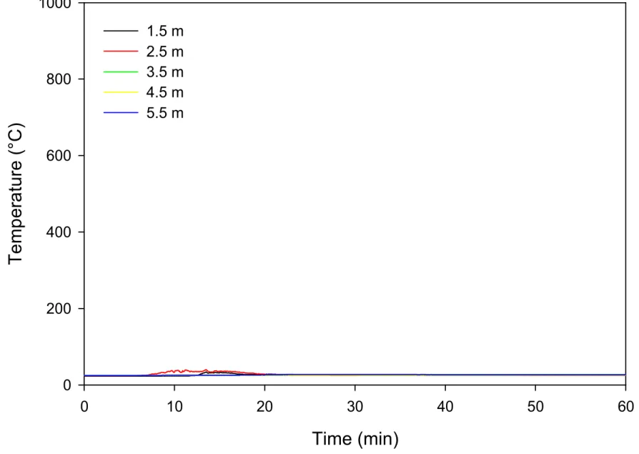
The temperatures recorded by the thermocouples within the test assembly between the insulation and the WRB are shown in Figure 7. This figure shows no significant rises at any of the locations. The highest recorded temperature was 34°C.
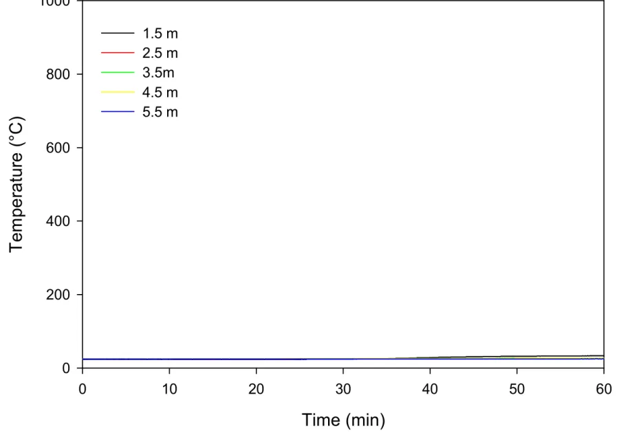
Temperatures recorded by the thermocouples behind the wall assembly, on the surface of the 15.9 mm gypsum board at the interface with the simulated CLT, are shown in Figure 8. There were small temperature increases at the 1.5 and 2.5 m heights during the propane fire exposure. Subsequently, there was minimal or no increase in
temperature.
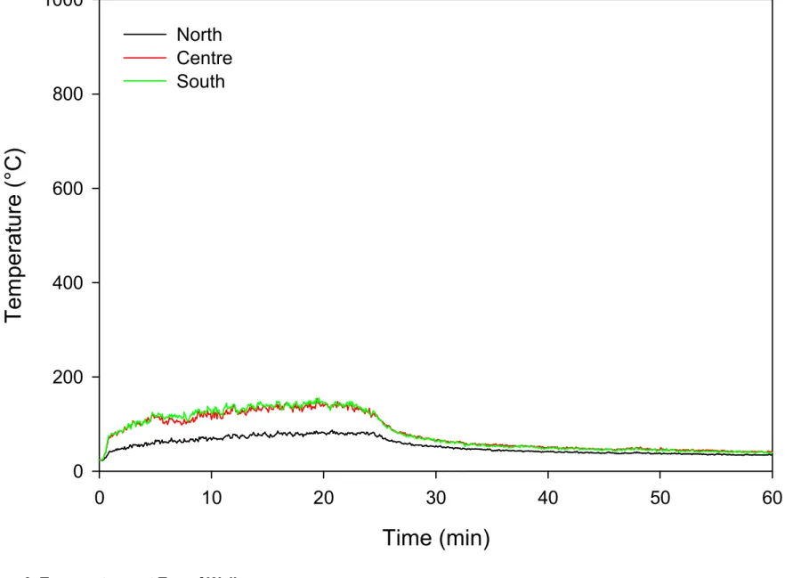
The fire plume temperatures measured at the top of the wall are shown in Figure 9. The temperatures at the top of the wall reached a maximum of 154°C. The temperatures decayed after the propane was shut off. There was minimal or no increase in
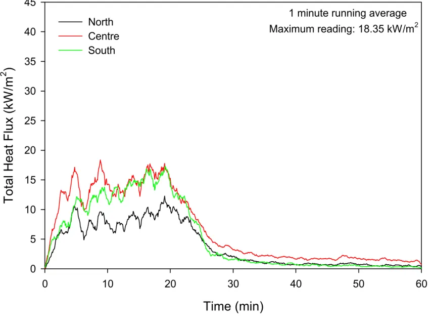
temperature with the small fire that occurred after a portion of gypsum sheathing fell off. Heat Flux – The total heat flux to the wall, as measured 3.5 m above the top of the window opening, is shown in Figure 10. The data shown in this figure has been smoothed using the procedure of a running average over one minute.
The heat flux values at all three locations showed a steady rise in exposure over the first 5 minutes followed by various uneven peaks. The maximum one-minute averaged values recorded at the 3 locations were 18.4 kW/m2at the centre location, 12.3 kW/m2 at the north location and 17.3 kW/m2at the south location.
The heat flux values decayed after the propane was shut off at 25 min. There was minimal or no increase in heat flux values with the fall off of the small piece of gypsum sheathing at approximately 47 min.
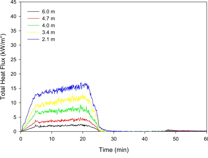
The heat flux values measured by the heat flux meters installed on the mast are shown in Figure 11. The heat flux at the 2.1 m height reached 17.0 kW/m2, at the 3.4 m height it
reached 12.8 kW/m2, at the 4.7 m height it reached 4.9 kW/m2and at the 6.0 m height it
reached 2.5 kW/m2. The heat flux at 2.4 m from the wall at the 4.0 m level reached 9.3
Time (min)
0
10
20
30
40
50
60
T
em
p
e
ra
tu
re
(
°C
)
0
200
400
600
800
1000
1200
1400
Room Average
Window Opening Average
Time (min)
0
10
20
30
40
50
60
T
em
pe
ra
tu
re
(
°C
)
0
200
400
600
800
1000
1.5 m
2.5 m
3.5 m
4.5 m
5.5 m
Time (min)
0
10
20
30
40
50
60
T
em
pe
ra
tu
re
(
°C
)
0
200
400
600
800
1000
1.5 m
2.5 m
3.5m
4.5 m
5.5 m
Time (min)
0
10
20
30
40
50
60
T
e
m
p
er
a
tu
re
(
°C
)
0
200
400
600
800
1000
1.5 m
2.5 m
3.5 m
4.5 m
5.5 m
Time (min)
0
10
20
30
40
50
60
T
em
pe
ra
tu
re
(
°C
)
0
200
400
600
800
1000
North
Centre
South
Contract # B-7000
Time (min)
0
10
20
30
40
50
60
T
o
ta
l H
e
a
t
F
lu
x
(k
W
/m
2)
0
5
10
15
20
25
30
35
40
45
North
Centre
South
1 minute running average
Maximum reading: 18.35 kW/m
2Contract # B-7000
Time (min)
0
10
20
30
40
50
60
T
o
ta
l H
ea
t
F
lu
x
(k
W
/m
2)
0
5
10
15
20
25
30
35
40
45
6.0 m
4.7 m
4.0 m
3.4 m
2.1 m
Contract # B-7000
9 PERFORMANCE OF THE WALL ASSEMBLY
A) Flame Spread over Exterior Face
After the propane burner was turned off, this test was followed with a 35 minute observation period at the request of the client. (Since its first publication in 1992, CAN/ULC-S134 has required that the assembly continue to be observed until all fires self-extinguish. However, in most cases, the fires that remain after the propane is shut off are very small and pose a limited hazard. In the 2013 edition of the test standard, which was used as the basis for these tests, the test is observed for a maximum of 60 min after the ignition of the burners. During this 60 min, the test assembly must meet the requirements in the 2010 NBC for limiting the maximum flame height and 1-min
averaged heat flux at the 3.5 m height.)
During the fire exposure, other than the occasional crackling sound, the wall showed no significant damage from the test. Once the flames were reduced, small cracks in the gypsum sheathing were visible at the top of the window opening below the 0.5 meter mark. Following the fire exposure, small flames progressed slowly through the assembly near the top of the window opening. The fire started to gain momentum after a piece of gypsum sheathing fell out at around 47 minutes.
B) Incremental Radiant Heat Flow to the Wall above the Window Opening
The maximum one-minute averaged value of the total heat flux on the test wall at 3.5 m above the top of the window opening was 18.35 kW/m2. This is less than the 35 kW/m2
specified in Sentence 3.1.5.5.(4) of the 2010 NBC [1]. For comparison, the value for a noncombustible wall (Marinite) is 16 kW/m2. (Note: Marinite is a thermal structural board
insulation, which is a formed from calcium silicate with inert fillers and reinforcing agents. This material was used to provide the noncombustible wall, which was used for
calibration and reference purposes in the initial test series used to develop the test method [5]).
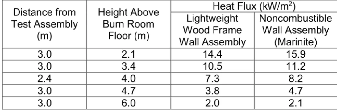
C) Incremental Radiant Heat Flow at Target Mast
The average values of heat flux density at the target mast over the 15 min period of steady gas supply, as compared to a noncombustible wall (Marinite), were:
Table 1. Average Values of Heat Flux at Target Mast.
Distance from Test Assembly (m) Height Above Burn Room Floor (m) Heat Flux (kW/m2) Lightweight Wood Frame Wall Assembly Noncombustible Wall Assembly (Marinite) 3.0 2.1 14.4 15.9 3.0 3.4 10.5 11.2 2.4 4.0 7.3 8.2 3.0 4.7 3.8 4.7 3.0 6.0 2.0 2.1
D) Damage to the Wall Assembly
Figure 12 shows the wall assembly at two different times during the fire exposure.
Figure 13 shows the extent of the damage to the wall assembly after the test (with some gypsum sheathing manually removed or pulled back upon test completion for
examination of area beneath).
(b) 11 Minutes After Ignition. Figure 12. Wall Sample During the Fire Exposure.
10 REMARKS
1. The test facility and test method, as described in this report, conform to the
requirements of Article 3.1.5.5 of the 2010 edition of the National Building Code of Canada. The test was conducted in accordance with CAN/ULC-S134 [3].
2. The extent of damage to the test wall assembly was limited to an area above the window opening to a height of 3.0 m during the fire exposure, mostly in the form burnt gypsum sheathing paper facing. There were a few fissures in the gypsum sheathing on both sides of the centerline below 0.5 m.
3. During the fire exposure there were flames to 3.0 m above the window opening. This is less than the 5 m limit for flame spread distance specified in
Sentence 3.1.5.5.(3) and defined in Appendix A (A-3.1.5.5.(3)) of the 2010 NBC [1].
4. The maximum one-minute averaged value of the total heat flux density on the test wall assembly, at 3.5 m above the top of the window opening during the fire exposure was 18.4 kW/m2. This is less than the 35 kW/m2specified in Sentence
3.1.5.5.(4) of the 2010 NBC [1].
5. A small fire continued to burn inside the wall cavity after the propane was shut-off at 25 min. This fire was limited to the header and the studs immediately above the window opening. There was limited or no propagation of this fire until after some of the gypsum sheathing fell off at approximately 47 min. The fire remained relatively small and was easily suppressed once the test was concluded.
6. There was limited damage to the XPS foam insulation in the cavity. Most of the damage was limited to the area immediately above the window opening. The maximum height of the damaged area was approximately 2.5 m at the center of the assembly.
7. There was minimal or no damage to the WRB and the simulated CLT.
11 ACKNOWLEDGMENTS
Financial and in-kind support for the project provided by the following organizations is gratefully acknowledged:
Canadian Wood Council
Forestry Innovation Investment BC FPInnovations
Ontario Ministry of Municipal Affairs and Housing National Research Council Canada
Natural Resources Canada Régie du Bâtiment du Québec
Quebec government (Société d’Habitation du Québec, Société Immobilière du Québec, Ministère des Ressources Naturelles)Extensive technical input by staff from collaborating organizations is also gratefully acknowledged:
Rodney McPhee and Ineke Van Zeeland, Canadian Wood Council. Christian Dagenais, Mohammad Mohammad and Lindsay Osborne,
12 REFERENCES
1. 2010 NBC, National Building Code of Canada, National Research Council, Ottawa, Ontario, 2010.
2. Su, J., Gover, B., Lougheed, G., Benichou, N., Swinton, M., Schoenwald, S.,
Lacasse, M., Di Lenardo, B., Mostafaei, H. and Pernica, G., Wood And Wood-Hybrid Mid-Rise Buildings, Phase 1: Scoping Study, B4726.1, National Research Council, Ottawa, Ontario, 2011.
3. CAN/ULC-S134, Fire Test of Exterior Wall Assemblies, Underwriters Laboratories of Canada, Ottawa, Ontario, 2013.
4. Chauhan, R., Gosselin, G., Oleszkiewicz, I. and Richardson, K., Committee Paper #2 on Combustible Cladding, National Research Council, Ottawa, 1988.
5. Oleszkiewicz, I., Fire exposure to exterior walls and flame spread on combustible claddings, Fire Technology, Volume 26, 1990, p. 357-375.
6. Bijlos, M., Lougheed, G.D., Su, J.Z. and Benichou, N., Solutions for mid-rise wood construction: Cone calorimeter results for materials used in standard exterior wall tests, Report A1-100035-01.3, National Research Council, Ottawa, ON, 2014. 7. CAN/CSA-A82-27-M91, Gypsum Board, Canadian Standards Association, Toronto,
ON, 1991.
8. CAN/ULC-S101, Standard Methods of Fire Endurance Tests of Building Construction and Materials, Underwriters Laboratories of Canada, Ottawa, Ontario, 2004.