Publisher’s version / Version de l'éditeur:
Vous avez des questions? Nous pouvons vous aider. Pour communiquer directement avec un auteur, consultez la première page de la revue dans laquelle son article a été publié afin de trouver ses coordonnées. Si vous n’arrivez pas à les repérer, communiquez avec nous à PublicationsArchive-ArchivesPublications@nrc-cnrc.gc.ca.
Questions? Contact the NRC Publications Archive team at
PublicationsArchive-ArchivesPublications@nrc-cnrc.gc.ca. If you wish to email the authors directly, please see the first page of the publication for their contact information.
https://publications-cnrc.canada.ca/fra/droits
L’accès à ce site Web et l’utilisation de son contenu sont assujettis aux conditions présentées dans le site
LISEZ CES CONDITIONS ATTENTIVEMENT AVANT D’UTILISER CE SITE WEB.
Nanotechnology Vol. 6: Energy and Environment, pp. 347-398, 2013-07-01
READ THESE TERMS AND CONDITIONS CAREFULLY BEFORE USING THIS WEBSITE. https://nrc-publications.canada.ca/eng/copyright
NRC Publications Archive Record / Notice des Archives des publications du CNRC :
https://nrc-publications.canada.ca/eng/view/object/?id=13ce4bb0-cf58-40df-a625-f9bb624fb369 https://publications-cnrc.canada.ca/fra/voir/objet/?id=13ce4bb0-cf58-40df-a625-f9bb624fb369
Archives des publications du CNRC
Access and use of this website and the material on it are subject to the Terms and Conditions set forth at
Failure analysis in energy related materials and coatings: role of
nanostructured materials for sustainable solutions
Energy, Mining and Environment National Research Council of Canada 1200 Montreal Road, Ottawa, ON, K1A 0R6, Canada
Corresponding author: E-mail: farid.bensebaa@nrc.ca
15
Failure Analysis in Energy Related Materials
and Coatings – Role of Nanostructured
Materials for Sustainable Solutions
FARID BENSEBAAABSTRACT
Improving performance and lifetime cost of current base materials and coating solutions require detailed failure analysis. Materials corrosion has a significant financial, environmental and safety impacts in the petrochemical and transportation sectors. Alternative materials have been recently developed to improve performance over cost ratio. Nanomaterials are introduced at even increased pace within components in numerous industrial sectors. In few cases, nanostructured materials and films improve the performance/cost ratio while reducing utilization of raw materials and environmental impact. In most cases, detailed failure analysis is important to quantify advantages and shortcomings of nanomaterials. In particular, detailed and complementary materials science and materials engineering investigation is recommended. This will allow better understanding of the relationship between the composition and structure in one hand and functional properties on the other hand.
Key words: Failure analysis, Nondestructive testing, Corrosion, Nano-materials, Coating.
1. INTRODUCTION
Several engineering materials with different attributes have been developed. This includes metals, plastic, ceramics and hybrids. Based on their attributes, these materials are designed to operate under specific
conditions for a maximum period of time. Failure of metallic and non– metallic components is often due to materials building blocks utilization at the limit of their capability. Other related issues such as defects, bad design and utilization conditions are also important. Reduced lifetime has cost and environmental impacts. Future developments in materials science and engineering will have a significant impact on the energy and environment footprints in numerous industrial sectors. Understanding current limitations of existing materials could help in designing future products using alternative materials that include nanomaterials and alloys. Reduction of raw materials input through nanomaterials utilization with potentially longer service time is achievable. Indeed, optimized nanomaterials integration improves the thermo–mechanical properties.
Miniaturization requirements and the development of advanced characterization techniques have increased interest in nanoscopic materials structures within academia and industry. A direct relationship has been established between the nanograin size and the mechanical properties of engineering materials. This leads to the Hall–Petch relationship which explains the increase in yield strengthening when using smaller grain sizes[1]. Nondestructive techniques are used to test objects and systems
during the manufacturing process and utilization stages. Predicting lifetime of products is a challenging academic problem with significant financial consequences.
Two important types of deleterious conditions that could affect the lifetime of a given product have been identified[2]. First, discontinuities
such as cracks and holes may give rise to failure. Second, inadequate material properties will reduce product lifetime. Degradation of materials and products lead to significant financial losses and even casualties if defectuous vessels or pipes in plant or airplane are not detected in time. Corrosion, involving chemical reaction followed by deterioration of the functional properties is a common failure in the chemical and petrochemical industries. Others common failure modes include fatigue, fracture, fretting, creep and wear (erosion). Fouling, buckling, mechanical overload, thermal shock, and yield are other possible failure modes. Detection and quantifying corrosion and other defects for preventive and failure mode understanding are critically important.
Early failure detection and effective lifetime estimation are thus very importan t. Nondestructive techniques (NDT), also refereed as non destr uctive testing (NDT), n ondestructive method (ND M), nondestructive evaluation (NDE) or nondestructive inspection (NDI), play a critical role. There are numerous groups of NDTs, including ultrasonic, vibrational, infrared, optical and tomographic. Other techniques including liquid penetrant and leak detection techniques are complementary and critical. All these techniques often involve three important aspects: instrumentation, methodology and data interpretation. It is unlikely that a single test will be sufficient to identify a defect and quantify the extent of
349 Failure Analysis in Energy Related Materials and Coatings
its severity. Even when the defect is quantified, the origin of this defect must be identified. Such understanding will help improve the fabrication process and utilization of alternative source of raw materials and components. A preventive maintenance operation could be carried out with early and non–destructive surface defects detection. This could save money and time by replacing or fixing a single defectuous part instead of replacing the whole plant.
NDT is not sufficient to complete a failure analysis. New products always require improvements based on laboratory and field data. Materials scientist and materials engineer must work under a closer collaboration not only to understand the origin of failure but also to propose durable and sustainable solutions. Indeed, a detailed understanding of the origin of the failure could help in designing improved next–generation products and prevent failure repeat. Defect detection and product testing are not sufficient if the exact root of failure is not obtained. Detailed material characterization should complement information obtained from NDT to provide a complete failure analysis. Destructive techniques are used to reveal mechanical properties under static and dynamic loading conditions. Other destructive techniques are used to reveal chemical composition and structural properties. Combination of destructive and non–destructive provides complementary information when conducting failure analysis. Often failure occurs when there is an overlap between the spectrum of the stress load of the structure and the components materials resistance distribution.
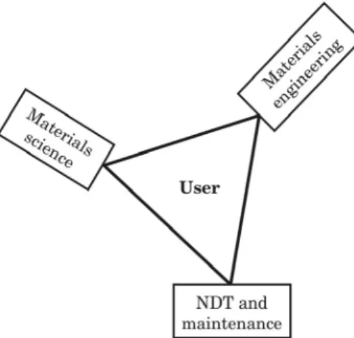
A complete failure analysis involves (i) materials and part manufactu-ring, (ii) product manufacturing and installation, (iii) material and part characterization within a laboratory, (iv) field detection and testing, and (v) simulation and modelization. These activities could be regrouped in three areas of expertise including materials science, materials engineering, and NDT including maintenance (Fig. 1). The process of optimization
requires input from all three fields. Unfortunately, collaboration between experts from these three fields is not optimum. There are very few publications addressing the importance of the collaboration between materials scientist, materials engineer and filed engineer (NDT/ maintenance).
For centuries, scientists and non–scientists have been searching for new materials with improved functionalities, performance and cost– effectiveness. Metals, ceramics and to less extend plastic materials are used in numerous sectors. The last decades numerous groups of advanced materials have been developed for different applications. This includes semiconductors, biomaterials, composites, carbon nanotubes, fibers and nanocoatings. These novel materials have been searched with great extend to address shortcomings of existing one and also to create new market opportunities based on novel properties. The end of last century has seen the emergence of nanomaterials likely to overtake metal and plastic as the base materials for future components and products[3,4]. Nanomaterials, with
at least one geometrical dimension less than 100 nm, include carbon nanotubes, nanofibers, nanoclays, nanocomposites, nanoporous materials, nanowires and nanoparticles. Nanomaterials will likely become the dominant building blocks in the future for several industries[3].
Materials science and engineering are key areas allowing building a database for a successful failure analysis. Often data obtained from these two areas are obtained separately under different operation conditions, making it difficult to establish a direct relationship. Materials engineering provides mechanical (e.g., young modulus), physical (e.g., thermal conductivity), chemical (e.g., oxidation) and fabrication (e.g., formability) properties. Materials science provides composition and structural data aiming at establishing a relationship between the desired properties and performance in one hand and the structural properties and characteristics on the other hand. Whereas materials structures are defined in the micro and nano–scale (nm to µm), materials engineering are often defined in the macro–scale (mm to m).
Most published reports focus on either materials science of materials engineering aspects of failure analysis. NDT, materials characterization, and alternative solutions are often covered only partially, often in different publications. Few publications provide a more general overview of the field. In particular with recent development in nanotechnology, a broader understanding of materials engineering and materials science is required from modern failure analysts. The present chapter intends to fill this void. Five main sub–areas will be covered in this study:
• Provide a context for the environmental and financial costs of current and future solutions;
351 Failure Analysis in Energy Related Materials and Coatings
• Clarify the cause of failure and prevent similar problem from occurring in the future;
• Detect the failure/defect early to prevent a catastrophe from occur and undertake a preventive maintenance;
• Provide alternative solutions for existing material and coatings; • Illustrate the potential role of nanomaterials and nanocoatings in
addressing current shortcomings.
2. ECONOMIC AND ENVIRONMENTAL COSTS
Corrosion is the main failure cause in several key industrial sectors. Corrosion has direct consequences on the bottom line of several industrial sectors including transportation, civil engineering and petrochemistry. Corrosion costs US industries around $170 billion a year[5]. The oil industry
has the biggest share of this loss. Service life, functionality, costs, and ecological considerations are important factors to consider when choosing the right base materials and corresponding environmental protection. Utilization of advanced materials, paints and inhibitors extend lifetimes of metallic structures. However their use should be balanced with their capital and OandM costs. Besides the economic cost, the overall environmental impact should be also assessed. Often this is difficult to conduct and sometimes leads to controversies.
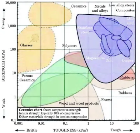
A wide range of engineered material classes including metallic metal alloys (e.g., steel), plastic (e.g., epoxy), elastomer (e.g., rubber), foam (polystyrene, titanium), composites (e.g., carbon–fiber–reinforced–polymer), ceramic (e.g., silicon carbide), and glass (e.g., soda glass) are currently used. Strength, stiffness, toughness, weight and maximum service temperature are the most important properties to consider when choosing base materials. Depending on the application, the overall weight of the system is important. Thus the quantification of these properties should include normalization to the materials density. Another important factor is the unit cost of these materials.
As shown in Fig. 2, the unit cost could vary by up to four orders of magnitudes across the different classes. Within each class of engineered materials there is a wide range in strength and cost values. In the case of metal based alloys (lead vs. steel, and steel vs. titanium), a variation of two orders of magnitudes in strength has been observed (Fig. 2). Thus, materials choice should allow the best combination of properties with the design constraints at the lowest cost possible.
“Life cycle costing of different corrosion protection solutions for steel has been reported[7]. Initial capital cost should not the only factor to consider
when selecting the best economical solution. Indeed, time until first maintenance, lifetime, and maintenance cost per year are also three critical
factors. The unit cost of different coatings has been evaluated over a nominal period of 50 years[7]. Often the initial capital costs of the different coating
processes are similar. The hot dip galvanizing process is the best long term solution. The lifetime unit cost of polymeric based coatings is 3-5 times more expensive[7]. Note that the coating solutions considered in this study
are those commonly used. It consists mostly of anti-corrosion steel protection. This conclusion may also change with interest and targeted ROI (return of investment). In the case of an ROI = 15%, increasing coating durability from 5 to 10 years is not economically viable if the capital cost is more than 50% of the total system cost[8]. Beyond 50%, it's better to replace
the whole system after 5 years. Extending the lifetime from 10 to 20 years will be economically viable only if the replacement cost is not significant[8].
If the interest rate are very low, investment to extend durability to 20 years or beyond should be privileged even if the capital cost is high[8]”.
Environmental impact during the product life cycle is currently used as selection criteria. External costs during manufacturing, use and recycling should be included in any comparison. Novel base and coating materials Fig. 2: Plot of the strength versus cost per unit weight for various classes of engineered materials. The different envelops enclose variety of compositions for a given class of materials[6].
353 Failure Analysis in Energy Related Materials and Coatings
should be evaluated using the overall technology–economy–environment scheme. Conducting a life–cycle assessment is often not easy because reliable and complete field data are lacking. Furthermore, the use of paints and inhibitors could end up in sea or ground, thus increasing the overall energy content and environmental impact of the metallic structures.
Comparing the ecological life cycle assessment of paint coating and hot dip galvanizing of steel has been reported. This assessment should include raw materials, manufacturing, utilization and disposal/recycling[9]. In this
comparison, the two coating solutions should provide corrosion prevention for a steel structure to be used for 60 years. The hot dip galvanizing system is obtained by immersion in molten zinc. A zinc layer thickness of 100 µm and a three–layer coating with a total thickness of 240 µm are considered. On–site cleaning and replacing the coating are needed after 20 and 40 years. The hot dip galvanized steel coating consumes fewer resources and has a reduced greenhouse effect[9].
3. FLAW, DEFECTS AND DEGRADATIONS ISSUES
Numerous causes of failure have been reported. They are divided into two groups. The first group of failures is related to intrinsic causes involving materials properties, design and fabrication processes. The second group of failures is related to extrinsic product operation conditions. Degradation of metal based components is manifested by either changes in geometrical properties or deterioration of functional properties. These changes are induced by mechanical load (creep failure), environment effect (corrosion failure) or a combination of both (hydrogen embrittlement). Pressure vessel and piping are recurrent damaged components. The list of failure types is quite long including corrosion, cracking, explosion, rupture and leakage. These failures could be caused by faulty design, improper fabrication practice, faulty inspection, damage during shipment and storage, damage during field fabrication and erection, improper materials, stress corrosion cracking, hydrogen embrittlement, creep and stress rupture, fatigue, over pressure, over temperature, welding problems, discontinuities, stress raisers, improper heat treatment, caustic embrittlement, brittle fractures and erosion[10,11]. Although there are more than 20 different ways a material
could fail[11], only the most important ones will be briefly described here.
3.1. Fatigue
Caused by repeated application of cyclic stresses, fatigue remains the most important failure mode of metal based parts and systems. Fatigue loading is the origin of many failures. Depending on the source of stress, mechanical fatigue and thermal fatigues are distinguished. Cycling, impact, corrosion and fretting fatigues are often reported as source of failure. Fatigue is a geometrical flaw in a material or component that develops progressively
into complete failure following repetitive fluctuating stresses and temperatures.
Fatigue initiates from discontinuities to develop into complete failure following repetitive stress around the area. Often, fatigue leads to crack initiation. Unfortunately, fatigue failures are difficult to predict. Up to five crack stages have been identified in fatigue failure[14]. Following crack
initiation (e.g., dislocation movement) and nucleation, a micro–crack is formed and propagated leading to macro–crack. The macro–crack propagation will lead to instability and fracture. Thus, fatigue failure results from propagation of an initiated micro–cracks. Micro–cracks are micro– structural features present in the starting materials (e.g., rod) or formed during the manufacturing process of the metallic part.
These micro–cracks are undesirable particularly when exposed to the surface part. Wear and corrosion increase on surfaces with micro–cracks. Micro–cracks also affect negatively the overall mechanical and thermal properties. Often micro–crack in homogeneous metals begins at the free material surface[12]. Models have been developed to predict fatigue limit
and lifetime of metallic products and structures[13]. Different sources of
stress may contribute collectively to fatigue failure. Understanding the microscopic origin of crack is not always straightforward. Often, it starts from a combination of dislocation movement and repeated load. Fatigue behavior is quantified by plotting the S–N curve, where S and N represent the stress (or strain) and the number of cycles respectively.
3.2. Corrosion
Corrosion is a chemical or an electrochemical process leading to a change in material composition. Metallic corrosion is omnipresent in petrochemical, construction, transportation and defense sectors. Corrosion results in deterioration of material properties and component failure, with a significant economic impact[5,15,16]. Direct and indirect costs of corrosion,
that includes lost productivity due to delays, outage, failure and litigations, amounts to about $9 trillion[17]. Besides the obvious cost related to failure
of parts, scheduled cleaning of the plant often requires the shutdown of the entire facility. Failure depends on the corrosion type and its extent. In some cases such as large metallic structures, corrosion is unavoidable and could be tolerated if the rate is below 0.1 mm per year. Failure also occurs when corroded parts are subjected to tensile stress. This has been reported in stainless steel parts. Corrosion of the metal components in the petrochemical refining processes contributes to poor plant efficiency. Different types of corrosion have been reported[16,18]:
• Uniform corrosion: the most common corrosion process affecting the whole surface. Steel rusting and silver tarnishing are good examples;
355 Failure Analysis in Energy Related Materials and Coatings
• Pitting corrosion: is a localized form of corrosion resulting in whole (or pit) formation;
• Selective leaching;
• Crevice corrosion: this corrosion occurs at small opening (crevice) between two metal surfaces or between metal and non–metal surfaces. An anodic environment occurs at this crevice due to a differential in oxygen content;
• Galvanic corrosion: This occurs for example when two dissimilar metals are joined in a corrosive electrolyte (e.g., sweater).
The different corrosion processes could be divided into high temperature and electrolytic groups[20]. Depending on the surrounding media and
environment, the coating and the base metal may be affected differently. At high temperature, the coating is attacked uniformly or selectively. The base metal may sustain stress corrosion, cracking, fatigue and hydrogen embrittlement. Electrolytic corrosion may give rise to pitting and crevice corrosions in the coating and base metal respectively. Different solutions are developed to prevent or control the different types of corrosion. This includes modification of the base metals composition, modification of environments surrounding the metallic components, change in the potential at metal–environmental interface, replace metal with non–metallic materials, or a combination thereof. Different surface modifications have been developed to address these various types of corrosions[19]. In the case
of surface coatings, the corrosion rate is reduced without eliminating the corrosion source.
Temperature, humidity and pollution are major contributors to corrosion. Thus, any anti–corrosion solution and system design should consider these factors. For example, rainfall can be beneficial by removing corrosive chemicals from the surface, or harmful when scanty rainfall leave water droplets that could promote corrosion. Proximity to sea will lead to cumulative effect from salt and humidity. Localized corrosion at discrete site leads to formation of crevice. This occurs following a breakdown in the protective passive film. Detailed understanding of these corrosive behaviors is challenging from both scientific and industrial points of views[21]. Hot
corrosion involving environment contamination other than oxygen, such as the case of gas turbine blades, is a major concern[22]. Sulphates, chlorides
and oxides combined with hot gas stream lead to formation of liquid–like deposit on hot alloy components. After an initial chemical attack and destruction of the protective coating, a degradation process of the base materials is initiated followed with a rapid oxidation.
Carbon steel constitutes about 80% of refinery components. It’s resistant to most common forms of corrosion, including pitting corrosion from water droplets, embrittlement from hydrogen, and stress corrosion cracking from sulphide attack. Low alloy steels containing chromium and molybdenum,
and stainless steels containing more chromium are used in more corrosive environments. Often special protection is added to the coated base materials. For example, coated steel based pipeline are enveloped with an insulation materials. Even in this case, a more subtle and sometimes difficult to detect corrosion occurs. Corrosion under insulation (CUI) is a localized corrosion at the interface that often remains visually undetected until it is too late[23].
This is particularly the case of CUI occurring in oil and gas pipelines.
Anti–corrosion is not an intrinsic property of a given materials composition. Often, it depends on the environment. This is illustrated by AISI 316 and AISI 304 stainless steels. The former (AISI 316) is resistant in neutral/chlorinated media and corrodes in oxidizing media[8]. The later
(AISI 304) is resistant to oxidizing media but corrodes in neutral/chlorinated media[8]. The surface interfacing the bulk materials with the environment
plays a critical role. Any surface change at the nano–, micro, meso– or macroscopic level will likely have consequences on the corrosion behavior. The following factors may affect corrosion[8]:
• Materials: Composition, crystallographic structure, grain size, texture, deformation state, residual stress, thermal gradient, and precipitates in/around the grain boundaries.
• Surface: Grain orientation, surface film, surface precipitates and inclusions, roughness, ligand complex, and inter–granular segregation.
• Environment: Composition, oxygen content, atmospheric conditions, pH, temperature, thermal cycling, thermal gradient, agitation and flow, applied stress, bacteria, and irradiations.
Different solutions are developed to address bulk materials (composition, thermo–mechanical and thermo–chemical treatments, and fabrication), surface materials (surface treatments, preparation, cleaning and coating), environment/medium (inhibitor, pH control, temperature control) or the whole system (cathodic or anodic protection). Synergetic effects of corrosion with other fatigue modes will accelerate the failure process. Often, corrosion induced discontinuities give rise to a stress that accelerate fatigue failure. On the other hand, cyclic loading will cause cracking and flaking exposing fresh metal surface prone to corrosion.
3.3. Wear
Wear involves loss of material due to a mechanical process. Direct and indirect economical losses due to wear may represent up to 1.5% of GNP[24].
Detrimental effects due to wear damage of components have been recognized in different industrial fields. This leads to adhesion failure, fatigue, abrasion and tribochemical reactions. Erosion leads to continuous wall thickness diminution with potentially fatal consequences when high pressure and
357 Failure Analysis in Energy Related Materials and Coatings
hazardous chemicals are involved. Different wear mechanisms have been reported and discussed below[19].
The mechanism process involving metal part wear by small impacting particle has been also shown to contribute to failure[25,26]. Abrasion and
erosion are two important wear processes of metallic parts. Abrasion of metal part is due to sliding of solid particles on a surface or between two surfaces. Erosion is caused by the impact of high velocity solid particles carried by a fluid. There are also other wear processes involving fatigue, fretting and biological species[27–29]. Corrosion and wear may collectively
lead to an accelerated fatigue failure. For example, an eroded surface is more likely to be affected by a corrosion process. Combined effect of corrosion and erosion is believed to have an even more damaging effect when compared to the two processes acting separately[27]. Fretting and biological
processes are other factors contributing to wear. Fretting occurring between two contacting surfaces, can act as a nucleating point for crack propagation
[28]. Fretting involves both mechanical and chemical processes when two
contacting surfaces are interacting.
3.4. Creep Degradation
Creep degradation is a progressive deformation of a component under constant load at high temperature. Creep degradation and deformation could lead to rupture. Creep rupture (failure) occurs when the accumulated creep strain results in deformation followed by separation into two parts. The time–dependant deformation features of metallic part at about 0.4Tm
or higher (Tm = melting temperature) is often used to qualify creep fracture
during the design stage. Strain vs. time curves under constant tensile load and at 0.4Tm or higher are thus measured and reported. Introduction of
high temperature alloy has lowered significantly creep failure in power plants.
3.5. Ductile and Brittle Fracture
Besides corrosion, crack and creep fracture, ductile and brittle fractures are two other causes leading to failure. Ductility of metal particularly at high temperature is very important for metal forming parts. Contrarily to ductile fracture, brittle fracture does not involve plastic deformation. Brittle metals are characterized by rapid crack propagation. Characteristics of ductile fracture are different from brittle fracture. In brittle fracture, little or no necking is observed. Indeed the geometrical dimension of the new interface is similar to the original surface after fracture. However, there are differences between the two surfaces at the microscopic level. In ductile fractures a necking is observed. The size of formed interface is reduced proportionally to the ductility level of the base materials.
Brittle materials are characterized by a linear elastic stress ()–strain () response and fracture with no plastic deformation[30]. Ductile materials
yield beyond the elastic region. A fracture may occur when the critical elongation is reached. A dimensional instability in tension (or necking) typically starts to develop at maximum load[30]. Under stress, a single solid
material may lead to fracture giving rise to two separates pieces. Depending on the plastic deformation, fracture is considered as ductile or brittle. Larger amount of plastic deformation is induced in the case of ductile materials when compared to brittle materials. Brittle fracture occurs when applied load exceeds the tensile strength of the material. Crack initiates from surface and internal defects that often lead to brittle fracture. Ductile fracture occurs in plastic material, whereas brittle fracture occurs in ceramic and hard materials. In the case of steel, ductility and brittleness properties are quantitatively tuned by controlling the amount of carbon. Other alloying elements and processes are also used to control the ductility and brittleness of metals.
When choosing the right metal, the ductile–to–brittle transition temperature should be the first parameter to consider. Metal liquid and hydrogen embrittlement are two environmental induced failures in the presence or absence of a mechanical load. Some metals lose their ductility upon contact with liquid metal. This often occurs during soldering, welding, and brazing. When contacted with liquid metal, fracture strains of ductile metal are reduced. This phenomenon is called liquid metal embitterment (LME). This behavior has practical implications since metal parts are subjected to different liquids. Welding and electropolishing used in refineries give rise to different form of degradations including embrittlement due to liquid metal and hydrogen. The presence of hydrogen trace during manufacturing or utilization in metallic components leads to embritlement. Hydrogen introduction in metal structure may occur during melt process. By reducing tensile strength, hydrogen embrittlement could cause failure even in the absence of external load. Gaseous hydrogen enables the growth of crack in steel based products. The pace of this growth is even faster at high temperature and pressure[31].
3.6. Discontinuities
Discontinuities are inherent part of structural materials. Indeed absolute homogeneity and continuity does not really exist. In this paper, discontinuity is defined as a sharp composition and/or spatial departure from material homogeneity and continuity. Discontinuities in structures may originate at any manufacturing step including alloy production, primary and secondary forming stages. Discontinuities could be also introduced during the component use, maintenance, and repair. Defects and cracks are two examples of discontinuities. These discontinuities are bulk or surface constrained often occurring in welding structures and corroded surfaces[32].
359 Failure Analysis in Energy Related Materials and Coatings
Defects in materials and parts may have different origins. Machining surface induced defects are commonplace. Combination of residual stress in one hand and incomplete fusion, shrinkage, cavities, porosities on the other hand often leads to failure[33]. Parts are made with materials that
could sustain any load below a critical value. However, localized stress concentration may lead to failure even below this critical load. This is particularly the case of cracks in the joint area of welded parts. For example, casting of a metal or an alloy from the melt gives rise to discontinuities. Cracks, often described as a planar breach, occur during the solidification process of the melt in a mould. Cracks result from other degradation processes that include defects and corrosion.
High temperature welding of two metallic parts lead to the formation of heat–affected zone (HAZ). The spatial distribution of the HAZ extends beyond the weld nugget[34]. Between the regions forming the welding and
the base metals, a gradual change in temperature occurs. As the temperature is reduced, finer grains are formed. Besides the HAZ, the weld consists of base materials and deposited metals. Weld properties are directly linked to its chemical composition and microstructure. The HAZ temperature approaches 3000ºC (welding temperature) around the weld nugget center. Often weld defects originate from poorly controlled welding process[34].
3.7. Thermal and Residual Stress
Although rare, metallic part failure could occur due to thermal and/or residual stress even in the absence of load. This type of stress locked inside of one (or an assembly of) part(s) occur either during manufacturing process or utilization. For example, residual stresses in welding of supermartensitic stainless steel could lead to cracking and failure[35]. Post–welding thermal
and peening treatments are often performed to minimize the thermal and residual stresses.
3.8. Oxidation and Carburization
Oxidation and carburization have been observed in fossil fuel based power plants and other high temperature processes[36]. These processes could
either enhance the properties of the metallic components or degrade them. In the later case, this could shorten their service–life. Other chemical processes including sulfurization, chlorination and nitridation may also occur, which potentially may lead to base metal degradations.
Al2O3, SiO2 and Cr2O3 formed on stainless steel provide good protection
to the base materials. However in some other cases, formed oxide is ineffective and even detrimental due to induced stress. Combined oxidation and carburization processes on Ni–Cr alloy that lead to surface oxide and
Cr2O3 precipitates formation (Fig. 3). This may lead to degradation under
specific conditions[37]. Carbon diffusion and inter–crystalline carbides
formation give rise to degradation in mechanical properties. Carburization could induce cracking carburization. This occurs in Ni alloy in the presence of carbon compounds (CO, CH4) under low oxygen atmosphere.
Fig. 3: Schematic representation of chemical and microstructural changes occurring within high temperature alloy under carburizing–oxidizing environments[38].
4. NON–DESTRUCTIVE TECHNIQUES (NDT)
NDT could be considered the extension of human senses by using more sensitive and accurate electronic instrumentation. A loose definition links NDTs to an ensemble of methods used to test a product ensuring its fitness for service without any damage to the overall system and the environment[39]. NDTs allow evaluation of the properties of objects without
affecting its integrity. The main goal when using NDT is to find intrinsic variables and latent flaws within the tested product. There are three important aspects embodied within the NDT concept: methodology, instrumentation and intelligence. The last aspect (intelligence) involves data interpretation, understanding the failure mode, and propose solutions.
For each technique a pre–established methodology is often used in conjunction with commercial or home–made instruments. Difficulty in interpreting the resulting data depends on the nature of the sample and on the complexity of the technique. Every NDT has its own limitations. In most cases several NDTs are required for a complete analysis of a single part or system. Often a minimum of two methods are required. One dedicated to probe surface characteristics of the part. The second one will be dedicated to below surface or bulk characteristics.
Practical aspects of NDTs have been recently reviewed in a recent book[40]. A more complete description of the major nondestructive techniques
and their applications has been reported in a recently published Book Series[41]. Table 1 provides the principles, application along with the
361 F a ilu re A n al y si s in E n erg y Re lat ed M a teria ls an d C o a tin g s
Table 1: Overview of the characteristics of major NDT methods
Areas of application Advantages Limitations Cost Optical Quick inspection during manufacturing and in the field Wide application and easy to use Limited to accessible surface defect Low Infrared thermo-graphy Product inspection during manufacturing and in the field Highly sensitive Require proper training; limited to small surface area of thin objects Medium Acoustic emission Welding and equipments under stress Large area; failure analysis Require proper training; direct contact between the sensor and analyzed object High Ultrasonic Any object allowing sound transmission Quick and detailed failure analysis Require surface finish High Radio-graphic Allows inspection of most materials during manufacturing and in the field Allows bulk analysis Thick and dense materials; safety Very high Microwave Small and large ferromagnetic based objects Fast and easy to use Limited to large surface flaws Medium Vibration Damage evaluation at interfaces in the field or in controlled environment Large structure; predict failure Low sensitivity; complicate to setup Very high Eddy current Flaw detection Quick in-situ analysis Limited to conductive materials; require skill and training Medium Dye and magnetic penetrant Most materials with surface flaw Easy to use and very sensitive Bulk discontinuities accessible from the surface; surface preparation Low Leak testing methods Leaking vessels and seals Very sensitive and definitive Once there is a leak, it’s often too late. High
advantages and limitations of the main NDT covered in this article. These techniques will be described in the following paragraphs. Numerous attempts have been made to classify these techniques along different groups[2]. Often they are classified as active or passive techniques. In active
techniques, an excitation source to induce a reaction is used. Reflected techniques are distinguished from through–transmission, where an excitation source and detector are placed on the same side of the tested object. The last classification is based on deterministic and probabilistic concepts. Indeed, there is always an intermediate range between easy to detect large flaw and undetectable ultra–small flaw. This intermediate range is characterized by probability of detection (POD).
4.1. Optical Methods
Optical evaluations including visual inspection are often used as the first step in any NDT study. Direct and remote visual inspections are distinguished. In the first case, visual aids (mirrors, telescopes, cameras) are used when the surface is easy to access. Visual testing (VT) allows identifying and localizing the majority of defects. With the help of a lighting system, visual inspection allows localization of defectuous piece at the surface and within large components. Remote visual testing (RVT) is accomplished using borescopes, fiberscopes, and video technology. Sometimes more sophisticated optical techniques are needed when defectuous areas are not accessible or too small.
For small–diameter tube and other components a borescope is often used[43]. Borescope consists of an objective lens, one or more relay lenses
and an eyepiece. The overall borescope magnification is a convolution product of the magnification of these three components. Typically a magnification of 10x is obtained. Today video borescopes are used to image defects. This is particularly of interest when inhomogeneous distribution of defects requires hundreds of data points. Optical microscopes have been used to probe defect at even higher magnification. Long distance and portable microscope with a working distance up to 400 mm has been developed.
Other optical techniques are also developed. Topography has been used to characterize the surface of steel[44]. However, topographic characteristics
are not without any consequence on the surface chemical properties. Sherography has been used to detect and characterize defect flaws[45].
Although laser testing is considered an optical technique, it provides different and complementary information when compared to conventional visual techniques. For example they could provide microscopic profile of a surface with size ranging from micro–scale (µm) to macro–scale (m). There are numerous laser testing methods including profilometry, holography and shearography[46]. Using optical profilometer, surface roughness is
363 Failure Analysis in Energy Related Materials and Coatings
measured more accurately with better resolution than mechanical stylus. For small area defect laser holography provides even better detection capability. Shearography, an interferometric technique, has been used for surface deformation measurement (displacement and displacement– derivatives) in flaw detection, adhesive bonding integrity[45]. Laser
shearography uses CCD shearing camera to capture and reconstruct an image from light reflection of coherent laser beam impinging on a sample. A Laser ultrasonic technique has been used to evaluate coating thickness, elastic module, and density of WC–Co composite based thin film[47].
4.2. Infrared Thermography
Infrared thermography, also referred as thermal infrared (TIR), is omnipresent in numerous fields including inspection, maintenance, manufacturing, bioscience, medicine, military, agriculture, safety and astronomy[48]. It could be used as passive or active nondestructive technique.
In the first case (passive) the temperature of the analyzed object is naturally higher than the ambient. Difference in thermal radiation between the sample and the surrounding is exploited. In the second case (active) the temperature of the object is stimulated using an external source.
In a typical active infrared thermography setup, the part to be analyzed is transported to the setup for characterization[49]. Recent developments in
high sensitivity detector allowed effective onsite NDT. Although the object is thermally simulated in this case, other excitation options have been used. This is the case of vibro–thermography where low frequency mechanical vibration generates heat at cracks through frictions.
Recent cameras are used to record imaging. There are different configurations for non–destructive evaluation. This requires different configurations of infrared detection system, heated area and observation area. Both conventional pulsing thermography and modulated lock–in thermography have been used. Analysis by point, line or surface scanning is achievable[50], using single and multiple detector. Specific cameras are
developed to detect either thermal or infrared radiations. Recent develo-pment in focal plane array (FPA) provides high sensitivity and fast imaging.
The spectral radiant emittance of blackbody depends on the blackbody temperature. For a given temperature, spectral radiant emittance follows the Planck’s law characterized by distinct maximum value at a certain wavelength max = 2898/T[51]. For a given temperature, overall radiated
power of a blackbody at a given temperature is given by: Wb = xT4
Emissivity is often used to characterize infrared thermographic properties of materials. Emissivity at a given temperature is defined as the ratio of emitted heat radiation of the material to that emitted by a blackbody at the same temperature. A perfect blackbody has an emissivity of 1.00 compared to 0.95 for steel. There is close relationship between mechanical state of a materials and its temperature. For example material internal stress–strain state is directly related to the temperature[52]. There are several processes
(thermoelastic effect, thermoplastic effect, heat conduction effect) that could lead to changes in the mean temperature of the material. A temperature resolution up to 0.001°C and a spatial resolution down to several µm are achievable. Thermographic techniques are limited to surface or near surface flaws.
A thermoplastic theory establishing a relationship between the temperature and the material internal stress–strain state has been developed[52]. Thus measuring the sample temperature will provide a mean
to probe structural and fatigue states of materials. Fiber optic pyrometers allow remote application to avoid interferences from strong magnetic and electrical interferences. Another development is the utilization of laser to visually guide the device precisely to the probing area. Several thermographic techniques using color change thermometer and thermocouple sensors have been developed that are outside the scope of this article.
For 2D and 3D imaging, focal plane array (FPA) TIR using cooled and non–cooled detectors are used today[53]. Thermal detectors are also used in
single point IR thermometers. Fast responding quantum detectors (photodiodes) are used in FPA. High amplitude mechanical and small amplitude ultrasonic loadings have been used to characterize titanium based components fatigue[54]. Frequency modulated thermal wave imaging
has been recently developed to probe sub–surface defect[55]. On–line
corrosion detection of corroding tube under high–pressing boiling water is possible. It is also possible to evaluate wall thining of the boiled tube before and after corrosion[56].
4.3. Acoustic Emission Analysis
Acoustic emission (AE) is a passive non–destructive technique used mostly for flaw and defect detections[57,58]. Since most solid materials are endowed
with certain elasticity, the presence of a defect will induce a rapid release of elastic energy. Under mechanical, pressure or thermal stress solid body emits sonic or ultrasonic waves. Defects may occur in pressurized and evacuated systems, pipelines, infrastructure, aerospace, electrical power systems, process monitoring.
Placed on the surface of the body, AE sensors based on pieozoelectric transducers detect this signal wave and convert it to an electric signal in a
365 Failure Analysis in Energy Related Materials and Coatings
form of a burst[57]. AE transducers often operate in the 0.02–1.5 MHz range.
Details about acoustic–emission based testing technique is provided in Ref. [57]. Thus AE can help identify the presence of a defect even at the early stage of damage. AE allows flaw detection over large areas. This often require multi–sensors placed in contact with the surface. Although used mostly to identify and localize flaws (cracks, delamination, voids, honeycombing) in concrete and masonry structures[58], AE could be used
also in metallic structures. Characteristic features of the AE signal are used to identify and localize defects. AE allow defect detection and localization in small parts as well as in tanks with diameter of several dozen meters[57].
4.4. Ultrasonic Techniques
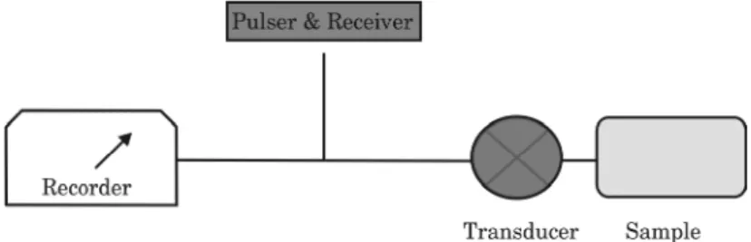
Ultrasonics techniques (UT) use high frequency sound (0.1–20 MHz) to excite the material pieces to be tested. Noncontacting and nondestrcutive ultrasonic techniques are widely used for quick flaw detection[2]. UT also
provides thickness, depth and type of flaw. As shown in Fig. 4, it has three main functional units. A pulse generator and receiver to drive the transducer; a high frequency (0.1–20 MHz) ultrasonic transducer typically consisting of piezoelectric plate sandwiched between two electrodes; and an electrical signal recorder. In a typical experiment, the presence of flaw (ex. crack) will induce a discontinuity in the ultrasonic wave front. This leads to a reflected sound signal characteristic of the flaw. The reflection mode is often used. Under certain circumstances the through–transmission mode could be also used. Depending on the ultrasonic parameter (velocity, sonic resonance, attenuation, backscattering) and the detection technique method (single point, imaging), there are numerous variety of ultrasonic NDT[59]. This includes phased array ultrasonics, time of flight diffraction
ultrasonics (TOFD), time of flight ultrasonic determination of 3D elastic constants, internal rotary inspection system (IRIS).
Piezoelectric plates are reciprocal systems, generating a voltage under applied stress or give rise to a deflection under applied voltage. Thus, the same piezoelectric is often used for generating ultrasonic wavelength and
to detect a deflection induced by a flaw. The recorder system consists of an amplifier, display and computer. Different types of data display of the output have been used. The A–scan where the amplitude versus time propagation time (or distance z) is recorded. In B–scan, amplitude as a function of y– coordinate (normal to z–coordinate) is reported by sweeping the transducer along this new coordinate. In C–scan, the transducer is swept along x– coordinate.
4.5. Radiographic Testing
Radiographic testing (RT) has been used since early 1900’s mostly in hospitals. It’s used to identify and localize internal flaws of a material using differential attenuation of –rays, X–rays, or neutrons. In a typical radiographic technique, a 2D image is provided corresponding to the intensity distribution of the attenuated radiation. Depending on the nature of the radiation beam, this radiography technique can be classified as – radiography, X–radiography or neutron–radiography. This technique is probably one of the most expensive NDT and it requires safety measures. Radiographic techniques are suitable for both metallic and non–metallic components.
High energy X–ray photons are used to produce a latent radiographic image dependent on the relative density of the object. Using an array of X–ary sensors instead of traditional radiographic film, a digital image is readily available for further signal processing. In the case of 3D radiographic imaging, a convolution of two dimensional sensors positioned around the object is used. In the case of neutron radiography, –rays radiation is emitted from objects bombarded by neutrons. This neutron radiographic image could be transferred directly or indirectly to a film.
4.6. Microwave Techniques – Ground Penetrating Radar (GPR)
Microwave techniques are particularly suitable for thick wall and relatively deeper sub–surface testing. Far– and near–field approaches have been used to evaluate the extent of surface cracks on metal parts[59]. Various
microwave sensors have been developed[60].
Used mostly in earth sciences and related fields[61], ground penetrating
radar (GPR) could be also used for testing buried pipeline without excavation. Using UHF and VHF microwave frequencies, GPR allows imaging of defects and cracks distribution in subsurface structures. The presence of areas with different dielectric constants affects directly the properties of the reflected microwaves. GPR radar has been used to identify and localize pipeline leaks[62]. GPR can detect voids and wetted soil due to
367 Failure Analysis in Energy Related Materials and Coatings
non–intuitive and difficult. Indeed these radiograms could be affected by numerous parameters that are difficult to quantify. Recently a combination of simulation and laboratory scale setup showed that the effect of these parameters could be quantified precisely[63].
4.7. Vibration Analysis
Vibration analysis techniques are often used in large structures such as bridges and dams. Vibration analysis involves many techniques based mostly on shaking a part and recording the amplitude and frequency of vibration. This experiment could be performed either on the field or under climate–controlled chamber. Frequency and damping characteristics of these vibration modes are often reported. Vibration analysis could be used to evaluate damage on the metal–to–metal adhesive joints[64]. Vibration
damping characteristics have been used to predict fatigue cracks in metallic parts[65].
4.8. Eddy Current Testing and Imaging
Eddy current technique (ET) has been used in petrochemical, electric power, infrastructure and aerospace. Characteristics of a circulating Eddy current that are generated by an external alternating magnetic field are affected by imperfections. Eddy current technique is quick, sensitive, versatile and do not require contacting with the part. Eddy current technique could be used for testing circular and flat products. Skin effect allows the evaluation of the micro–crack depth. The main drawback of eddy–current is the requirement for the probe to be scanned over the whole surface. However a multi–probe array coil has been developed[66]. Operation frequencies up to
10 MHZ have been used.
4.9. Dye and Magnetic Penetrant
Penetrant testing (PT) using dye and magnetic materials is widely used to directly detect surface cracks. Capillary attraction (or action) due to surface tension facilitates liquid penetration into tight openings of discontinuities. Oil and whiting penetrant methods have been used for years to identify flaws and discontinuities. This technique relies on the capillary action of a surface wetting fluid. Liquid penetrant technique based on fluorescent dye, magnetic particles and other markers are used to detect imperfections in nonmetals and nonferromagnetic materials.
Liquid penetrant operator will need to perform four main steps. First, the surface to be tested needs to be prepared using appropriate pre–cleaning procedure to remove surface coating, roughness, rust, and any foreign object on the surface. Rough and porous surfaces are difficult to inspect using
this technique. Second, apply appropriate amount of liquid penetrant and remove any excess remaining on the surface after a period of time (dwell). If needed, an emulsifier is applied before removing excess of penetrant. Third, apply a developer to cover the surface. Fourth, inspect surface to identify liquid penetrant signal using suitable lighting excitation. The fluorescent penetrant line is relatively simple allowing semi–automatic and/ or automatic operations.
Wettability (low contact angle), viscosity, and seeability (sensitivity) are three important characteristics of liquid penetrants. There are also other important characteristics of the PT: (i) easy access to surface specimen; (ii) penetrant retention until withdrawal during the development step; (iii) contrasting indication for higher sensitivity that is necessary; (iv) no chemical reaction tested specimen; (v) slow evaporation or drying tested[67].
Early utilization of PT is mostly based on oil and whiting liquids. Improved fluorescence properties allow visualization of the crack patterns details.
In the case of magnetic based liquid, surface and sub–surface defects induce a distortion in the magnetic flux lines. For ferromagnetic materials with surface and sub–surface defect dark or fluorescent magnetic materials are more appropriate. In this case wet and dry magnetic particle are used for testing. It allows leakage field Measurements. One of the advantages of magnetic liquid penetrant is the ability to detect and characterize defects under difficult conditions[68].
Major advantages of penetrant testing include portability, cost effectiveness, sensitivity, versatile, and effectiveness for production inspection[69]. Limitations include requirements for surface access to the
discontinuities, too many processing variables that include temperature variation, surface preparation and conditioning[69]. Furthermore besides
being usually messy, the liquid penetrant process does not provide an accurate estimation of cracks depth. This parameter is critical to evaluate the integrity of the system and the remaining lifetime.
4.10. Leak Testing Methods
Numerous leak testing techniques are available including bubble testing, helium mass spectrometry, halogen tracer gases, acoustic leak, thermal and infrared. These leak testing techniques have been used to test storage tanks and hermetic seals. Pressurized fluid (mostly gas) are used to create pressure differential to identify and quantify a leak in closed systems. Leak testing is used to ensure the integrity of plant and system that include hermetic fluid containers (e.g., hydraulic and refrigeration systems) and evacuated enclosures. Leak rate testing using evacuated or pressurized enclosure provides leakage rate Q (Pa.m3/s):
369 Failure Analysis in Energy Related Materials and Coatings
Q = V . P/t
where V is the enclosure volume, P pressure change during leak and t is the time interval during leak.
5. FAILURE ANALYSIS AND OPTIMIZATION
The main purpose of failure analysis study is mostly to prevent its re– occurrence in the future through continuous materials and process improvements. Some catastrophic failures can even lead to severe injuries and loss of lives, loss of productivity and costly litigation. Thus it’s important to prevent its occurrence or repetition. Failure analysis output could be also used for marketing, insurance claims and litigation issues. Complete failure analysis under controlled and real world environmental conditions, mechanical testing, chemical analysis, metallography and simulation are all very important. This analysis will allow for example to establish a relationship between the product properties in one hand and the structure, composition and manufacturing process on the other hand.
A combination of monitoring, preventative repairs and improvement in the quality of base materials and coatings should be adopted. Both off–line (non–continuous) and on–line (continuous) monitoring methods are used for preventative corrosion management. On–line corrosion monitoring and real–time information about the state and the cause of corrosion.
Up to four parties are involved in failure analysis[2,41,70] including design,
materials manufacturing, product manufacturing, and the end user. The interest of different parties could differ depending on the situation. Often, the final goal is to improve the performance/cost ratio of the product. The failure analysis will help determine the responsibility of each party in the case of litigation. Premature or catastrophic failure is ascribed to materials selection, engineering design, manufacturing and/or service conditions. Failure analysis involves a multi–tasking approach that include three steps. In the first step, functional failure characteristics are identified after undertaking preliminary examination of the failed part. This includes a detailed examination and non–destructive testing, and mechanical testing of the failed part. In the second step, structural failure characteristics are investigated including macroscopic observation, microscopic and chemical analysis of the failed portion and determination of failure mechanism. In the third step the root–cause failure is determined including the fracture origin. Often, testing and investigation under simulated conditions are undertaken. At the end a written report is prepared and provided to the stakeholders.
Based on this analysis, alternative materials and processes could be proposed to improve the properties of the product or the design of the whole
system. Materials properties (coating density, film composition, microscopic features) of the failed part are often carried in addition to the functional properties. Often, slow and destructive characterization techniques are used to extract geometrical and structural information of the materials used to build the object under test. Furthermore, NDT analysis provides information about the operation status of the products. Thus, establishing a three way relationship between NDT (non–destructive tests), materials properties (destructive tests) and physical properties (yield strength, abrasive resistance) is critical. Establishing this relationship is not always straightforward[70].
A designer will be keen on using the ideal material and manufacturing processes. However, this is not always possible because there are no ideal materials. Furthermore, there are numerous manufacturing and economical constrains. Indeed, there is a cost attached to any choice of material and fabrication process. Product are thus designed to perform under certain limits for a given service life. Understanding factors governing the components and an assembly including material characteristics is important to predict the best economical service life. Establishing the exact origin of failure and how to remediate it should remain the main focus of failure analysis. Failure of objects and materials are often traced back to design deficiency, fabrication defect, improper processing, utilization, operation and maintenance, defectious raw materials. Often a combination of several of these factors may contribute simultaneously.
Focusing on one issue when investigating the root cause of failed product will not provide satisfactory results. For example, even if we choose the perfect material to make tube, the overall system will likely fail if the welding process is defectuous. In this case, material properties and physical properties of the tube will not reveal any anomaly, although the installation could fail. In the case of casted components, deficiencies could cause failure depending on their size and utilization. Surface irregularities, inclusions, pinholes, cold and hot cracking are typical deficiencies. These deficiencies are enhanced by several factors including chemical composition, shrinkage allowance, casting design, coefficients of thermal conductivity. The choice of base materials and corresponding coating should be made based on the environmental conditions and the specific applications. Elaborate and expensive materials and coating are often used for longer lifetime particularly under harsh environment[71].
5.1. Quantitative NDT (QDNT)
Often NDT use benchmark data and operator’s judgment to qualify product and technologies. Quantitative nondestructive techniques (QNDT) are required to provide a complete understanding of the system performance and its relation with the fabrication process and maintenance procedures.
371 Failure Analysis in Energy Related Materials and Coatings
Unfortunately, it is not possible to perform QNDT with all NDTs[72].
However when this is possible measurement models coupled to the probability of detection (POD) concept have been developed. Predictive modeling using finite element analysis (FEA) is also used to complement investigation using NDT. Finite element analysis allows discretization of a component into many brick–like elements. The overall behaviour will be the sum of each individual brick. This technique is used to analyse component response to thermal or mechanical load. Furthermore FEA is very important in providing the remaining lifetime and effect of stress predictions, failure mode determination and solution proposal to remediate the problem information on component and assembly[73].
Failure may occur following bulk and surface loads. Bulk loads are due to mechanical, thermal and radiations forces, resulting in fatigue, fracture and ageing. Surface load, more prominent, are due to chemical, biological and tribological effects resulting in corrosion and wear. It’s important to distinguish between the mode of failure and cause of failure. For example if a reservoir has failed because of corrosion (cause of failure), this does not provide details about the failure mode. Indeed, even if appropriate coating solution has been applied to prevent corrosion, a faulty design may have contributed to failure. QDNT will help in developing appropriate solution that include:
• Replacing the base materials using advanced alloys or compounds; • Develop alternative coating;
• Change system and integration design
A complete failure analysis including QNDT should allow predicting the lifetime of the product. It is important to provide a probability that the product will perform within the specification while accounting for differences in supplied materials, manufacturing process and product utilization[74].
Thermography infrared techniques are often used qualitatively to probe thermal resistance on structural surfaces. Numerical models are developed to interpret surface temperature data obtained from building structure using infrared thermography[75]. The use of these numerical models allowed
providing important information regarding defects size and location. Furthermore, this quantitative analysis allowed also to detect deeper defects within the structure. This information is critical for accurate lifetime estimation.
5.2. Material Properties
Materials selection is one of the most important decisions when designing a product. The selection is based on the identified critical properties, manufacturing constraints, field operation conditions and cost. Besides raw
materials availability and cost, there are four important factors to consider when choosing the right materials building block. Chemical (oxidation, carburization, chlorination), physical (density, melting point), mechanical (creep, tensile) and manufacturability (shaping, cast, weld) properties are very important. Different structural combinations at different scales give rise to a variety of property sets (Fig. 5). In particular, atomic and sub– atomic arrangements have a direct consequence on the bond structure and strength. Recent achievements in controlling properties at the nanometer scale has lead to significant improvements in electrical, chemical, thermal and mechanical properties. Other materials characteristics also give rise to product improvements. Grain and grain-boundary size and composition directly affect mechanical properties.
Fig. 5: Structural levels influencing different properties [Adapted from Ref.76].
A recent review highlied the importance of establishing a structure–property relationship in the case of polymer nanocomposites[77]. These nanocomposites
could be used to address shortcomings of conventional base materials and coatings. Nanocomposites based on nanoparticle incorporation in (or combined with) a second phase provide numerous advantages for handling and integration[77,78]. These nancomposites could take numerous shape and
structures: (i) thin film; (ii) bulk material; (iii) porous material; (iv) agglomeration; (v) core–shell; (vi) surface and bulk dispersion; or (vii) hollow structure. Both the nano and micro–level structures could provide particular attributes to the final product. Alloying and surface passivation have been used to prevent or reduce corrosion kinetics for more than a century. Cr and to less extend Ni, N and Mo, have been added to iron to reduce corrosion.
Understanding the physicochemical, mechanical and manufacturability properties of the materials base is critical. Failure of metallic parts could be traced to the micro–structural properties and components chemistry. For example, combination of SEM and TEM analysis revealed the importance of slip bands for the initiation and growth of cracks. In the case of corrosion, chemical composition near the surface is critical. It has been shown that alloys and surface coatings are important to prevent rapid degradation of metallic part due to corrosion.
373 Failure Analysis in Energy Related Materials and Coatings
5.3. Materials Characterization
A complete failure analysis requires slow and destructive characterization of failed object components. Both macroscopic (mechanical) and microscopic (morphology, structure and composition) characterizations are often carried out. This characterization includes composition and structural properties. Establishing a relationship between structure and composition in one hand, and the functional properties of the materials on the other hand is critical for understanding the origin of failure. This characterization allows also developing improved materials. To optimize functional properties, composition and structure could be varied. Alloying, coating, fabrication process alteration and post treatments are often use.
5.3.1. Mechanical properties measurement (macroscopic)
The performance of a materials or a component often on a several combinations of properties. In the case of mechanical properties, mass density, Young modulus, strength, fracture toughness (resistance to crack propagation) and expansion coefficient are key material performance indicators. The properties of engineering materials are often grouped in charts to facilitate the choice. It’s worth noting that the different materials cluster together to form a relatively homogeneous class. As shown in Fig. 6, metallic based materials, clustering in the top right of the chart, provide the best combination of strength and toughness. These charts could be used by designer to identify the class of materials addressing their requirements.
Evaluation of mechanical properties implies testing under static and dynamic loading conditions. For example tension, compression, hardness, and creep tests are performed under static loading. Various stress analysis including thermal and mechanical testing are often performed under static conditions. Fatigue tests are made under dynamic load with repetitive cycling[79]. Residual stresses data are obtained using X–ray diffraction
usually on uniaxially loaded part[79]. Residual stress analysis provides
atomic structure changes. Macroscopic stress data are linked to the nanoscopic and atomic structure obtained by X–ray diffraction analysis. Residual stress analysis at the atomic scale has been reported.
5.3.2. Composition – chemical analysis
Three important parameter characterizations are important when analyzing the chemical composition. This includes concentration, chemical sensitivity and spatial resolution. A variety of micro– and nano– characterization techniques have been developed. Electronic and vibration spectroscopies provide valuable information about these parameters. Techniques with lowest detection limit and highest spatial resolution are specifically sought (Fig. 7). Basic techniques for elemental analysis include secondary ion mass spectroscopy (SIMS), time of flight SIMS (TOF–SIMS),

![Fig. 3: Schematic representation of chemical and microstructural changes occurring within high temperature alloy under carburizing–oxidizing environments [38] .](https://thumb-eu.123doks.com/thumbv2/123doknet/14109402.466414/15.918.264.653.289.481/schematic-representation-microstructural-occurring-temperature-carburizing-oxidizing-environments.webp)
![Fig. 5: Structural levels influencing different properties [Adapted from Ref. 76 ].](https://thumb-eu.123doks.com/thumbv2/123doknet/14109402.466414/27.918.208.710.411.567/fig-structural-levels-influencing-different-properties-adapted-ref.webp)
![Fig. 7: Detection range and spatial resolution of different analytical techniques [80] .](https://thumb-eu.123doks.com/thumbv2/123doknet/14109402.466414/30.918.209.715.179.516/fig-detection-range-spatial-resolution-different-analytical-techniques.webp)
![Fig. 8: Electron micrographs of a thermal barrier coating (TBC) obtained by (a) air plasma spray (APS) and (b) electron beam physical vapor deposition (EB–PVD) [82] .](https://thumb-eu.123doks.com/thumbv2/123doknet/14109402.466414/31.918.209.717.437.639/electron-micrographs-thermal-barrier-obtained-electron-physical-deposition.webp)
![Fig. 9: Variation of the strength/weight ratio as a function of temperature of diferent composites [90] .](https://thumb-eu.123doks.com/thumbv2/123doknet/14109402.466414/35.918.219.701.124.497/variation-strength-weight-ratio-function-temperature-diferent-composites.webp)
![Fig. 10: Evolution of the hardness as a function of the grain size [96] .](https://thumb-eu.123doks.com/thumbv2/123doknet/14109402.466414/36.918.280.645.726.971/fig-evolution-hardness-function-grain-size.webp)
