BEHAVIOR OF FRP-CONFINED CONCRETE
by
CHING AU
Bachelor of Engineering (Hon), Civil & Structural The Hong Kong Polytechnic University
(1999)
SUBMITTED TO THE DEPARTMENT OF CIVIL ENGINEERING IN PARTIAL FULFILLMENT OF THE REQUIREMENTS
FOR THE DEGREE OF
MASSACHUSETTS INSTITUTE
MASTER OF SCIENCE OF TECHNOLOGY
JUN 0 4
2001
at the
LIBRARIES
MASSACHUSETTS INSTITUTE OF TECHNOLOGY -May 2001
© Massachusetts Institute of Technology 2001. All rights reserved.,
Signature of Author
Department ofCivil Engineering lI1h May 2001 Certified by
Accepted by
/Oral Btiytik6ztUrk Professor of Civil and Environmental Engineering ThesJ4 Supervisor
To my
family
for theirBEHAVIOR OF FRP-CONFINED CONCRETE By
CHING AU
Submitted to the Department of Civil Engineering On 1 1th May 2001 in partial fulfillment of the
Requirements for the Degree MASTER OF SCIENCE
ABSTRACT
The use of fiber-reinforced plastic (FRP) materials as the confinement shells has become an attractive solution to retrofitting, strengthening, and constructing column-like structural systems. The method is considered superior to conventional concrete and steel jacketing methods in terms of confinement strength; post-retrofit ductility, sectional area, weight, and corrosion resistance; application ease; and overall project costs. The confinement effect can be achieved by winding fibers; wrapping and epoxy bonding of fabrics; or installing prefabricated shells. Applications have been extensive in the United States and Japan and there is an increasing trend in Europe and Asia recently.
Despite the extensive use of such new technology, fundamental aspects of the behavior of FRP-confined concrete have not been well understood. Experimental programs at this stage focus on the testing of various composite systems for axial strength increase, which are checked against existing models. Concrete core response, fiber response at various orientations, fiber orientation effects on overall column response, composite stack-up sequence effects, overlap joint effects, air pocket effects, and benefits of using angular fibers have not been fully investigated. Also, reliability and accuracy issues of various instrumentation techniques on composite surfaces have not been sufficiently investigated. The present research work is mostly experimental. It pinpoints various key issues that have not been dealt with previously. Several conclusions are drawn from the present study with respect to the following points: It is found out that gage aspect ratio, resistance, and orientation can have great impact on strain measurements. Concrete core of the column can crush locally and crack globally under high and low confinement strengths respectively. Fracture, buckling, and rigid body reorientation can occur, depending on the orientation of the fibers. Angular fiber wraps generally give more ductile mode of failure. Stack-up sequence of different types of fibers can have positive or adverse effect on the wrapped concrete in terms of failure modes and ultimate strength. Overlap joint can give rise to undesirable bending effect. Air pockets promotes post-peak stress reduction rate.
Thesis Supervisor: Oral BUyikiztUrk
Acknowledgements
I would like to extend my deepest appreciation to Professor Oral BUyUktztUrk, my academic advisor as well as thesis supervisor for his advice, guidance, encouragement, and patience throughout the course of my MS education and thesis work at MIT. He is never too busy to listen to me and discuss about my ideas towards the present thesis work.
I am thankful to Professor Rafael Bras, Department Head of Civil and Environment Engineering at MIT, for granting the funding for material procurement and laboratory resources. This work could not be initiated and completed without this generous financial support.
I am thankful to Dr. John Germaine for his valuable suggestions and help on the instrumentation design and setup, leading to the success of this experimental investigation.
Special thanks to Mr. Robert Fyfe, Mr. Scott Arnold, Ms. Sarah Cruickshank, and Mr. Tyler Maas of Fyfe Co. LLC Ltd. for their provision and installation of their advanced composite systems as well as their suggestions, time and effort in providing and gathering material and technical information, bringing fullness to this work.
I am also grateful for the help and technical assistance of the laboratory research machinist Mr. Steven Rudolph.
Besides, I express my gratitude to my undergraduate research assistance, Alexander Allen, for his arduous efforts, thoughtful ideas, and friendship over the course of the research program.
Last but not the least, I appreciate the valuable and constructive comments, criticisms, and suggestions from fellow students Oguz GUnes and Erdem Karaca in my office. Finally, I would like to thank my love Joanne for taking care of me every single day patiently and unconditionally. Without her love, support, suggestions, and encouragements, I would not have gone through this work so happily.
M IT Libraries
Document Services Room 14-0551 77 Massachusetts Avenue Cambridge, MA 02139 Ph: 617.253.2800 Email: [email protected] http://Iibraries.mit.edu/docsDISCLAIM ER
MISSING PAGE(S)The Archives copy is missing pages 5 - 13.
This is the most complete version available.
List of Figures
2.1 Comparison of strength and stiffness of A36 steel, carbon and glass fibers
2.2 Typical strength variation with loading angle in a laminate with unidirectional fibers 4.1 Tyfo® SHE-5 IA uncured fabric ready to be trimmed to size for installation
4.2 Tyfo® S Epoxy ready to be mixed (Left = A; Right = B) 4.3 Broom cleaned cylinders ready for prime coat application
4.4 Tyfo@ S Epoxy mixing and thickening for prime coat application with a mechanical mixer operating at 500 rpm for 5 minutes
4.5 Prime coat application by a roller
4.6 Primed cylinders under curing for at least one hour (surfaces were darkened by the prime coat)
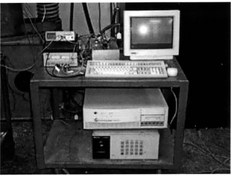
4.7 Impregnation/saturation of the fabric with a hand roller 4.8 Saturated fabric rolled to shape and ready for installation 4.9 Unrolling saturated fabric onto the cylinder surface 4.10 Squeezing entrapped air and ensuring a smooth finishing 4.11 Data acquisition system
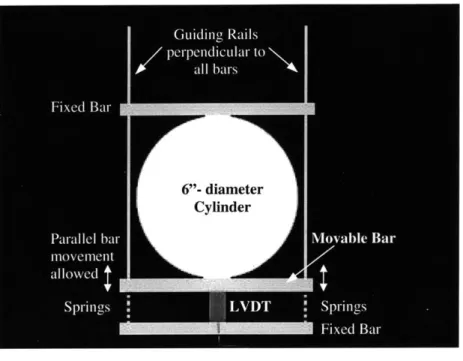
4.12 LVDT mounting spring system
4.13 Baldwin 200 kips loading frame with a specimen and the full setup 4.14 Computer-controlled system
4.15 Comparison of 350-ohm single gage and 120-ohm steel gage on CI - UC 1 - SP3 4.16 Comparison of 350-ohm single gage and 120-ohm steel gage on
C2 - WA1 - UCI - SP1
4.17 Comparison of 350-ohm single gage and 350-ohm tee gage on C2 - WA1 - UCI - SP3
4.18 Comparison of all strain gages on CI - W1 - SP3
4.19 Comparison of all strain gages on Cl - W1 - SP1
4.20 Fiber-gage misalignment study on C1 - UCI - SP3
4.21 Fiber-gage misalignment study on C2 - W1 - WAl - SP3
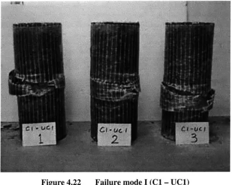
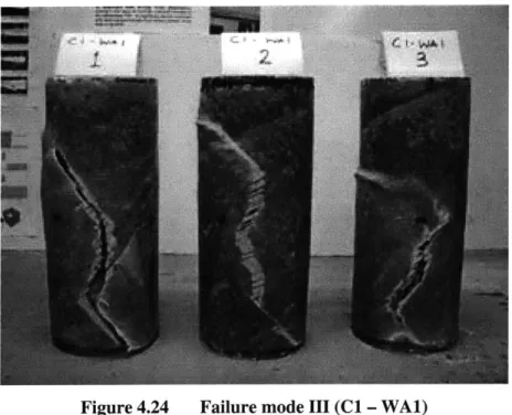
4.23 Failure mode II (Cl - WI) 4.24 Failure mode III (Cl - WA1)
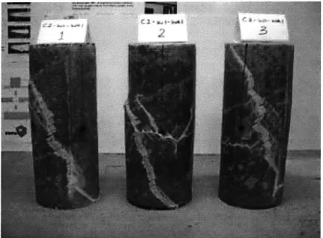
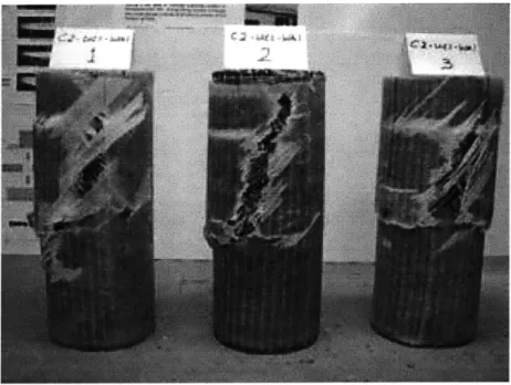
4.25 Failure mode IV (C2 - WI - WA1)
4.26 Failure mode V (C2 - UCI - WA1) 4.27 Failure mode VI (C2 - WAl - UCI) 4.28 Plots of axial stresses versus axial strains 4.29 Plots of axial stresses versus lateral strains 4.30 Plots of axial stresses versus volumetric strains 4.31 Axial strain curve Type I
4.32 Axial strain curve Type II
4.33 Differential axial strains due to an overlap
4.34 Complete delamination of C2 - WAI - UCI - SP3
4.35 Partial delamination of the WA layer of C2 - UCI - WAI - SP1 near the top end
(improper epoxy bonding result)
4.36 Intact bonding of C2 - UC1 - WAl - SP2 at fracture (proper epoxy bonding result) 4.37 Local fiber buckling / fabric wrinkling in Cl - WAl - SP3
4.38 Fiber reorientation in Cl - WAl - SP2
4.39 Concrete shearing fracture within fabric
4.40 Close-up of the snipping action on the longitudinal fibers of Cl - UCI - SP3 4.41 Fracture wings straightened up manually after test; crushed concrete core; intact
FRP-concrete bond on the wings
4.42 Sound concrete condition at the unconfined top 4.43 Overlap debonding in Cl - WAI - UCl - SP3
4.44 Overlap bond length of about 2.5" (or 13% of the circumferential length) 4.45 Doubly stressed actions on a strain gage
4.46 Different stresses for a given displacement on UC and WA fibers
4.47 Intact inner WA layer but ruptured outer UC layer of C2 - WAI - UCl - SPI
5.1 Nonlinear relationship of confined strength and confinement pressure 5.2 Nonlinear relationship of peak strain and confinement pressure
5.3 Comparison of analytical models with experimental results of the Cl - UC1 composite system
5.4 Comparison of analytical models with experimental results of the C2 - WAl - UC and C2 - UC1 - WA1 composite systems
5.5 Comparison of analytical models with experimental results of the CI - W1 composite system
5.6 Comparison of analytical models with experimental results of the Cl - WAl composite system
5.7 Comparison of analytical models with experimental results of the C1 - WI - WAI composite system
5.8 Comparison of the Proposed Bilinear Model with experimental results of the
CI - UC 1 composite system
5.9 Comparison of the Proposed Bilinear Model with experimental results of the C2
-WAI - UCI composite system
5.10 Comparison of the Proposed Increasing-Decreasing Model with experimental resu
of the CI - WI composite system
5.11 Comparison of the Proposed Increasing-Decreasing Model with experimental resu
of the C1 - WAl composite system
5.12 Comparison of the Proposed Increasing-Decreasing Model with experimental resu
of the C2 - WI - WAl composite system
1
Its
Its
List of Tables
2.1 Mechanical Properties of E-Glass and S-Glass Filaments
2.2 Comparison of Cost and Thickness of Various Forms of Fiber Reinforcement (Rosato 1997)
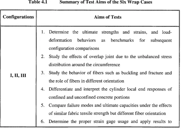
4.1 Summary of Test Aims of the Six Wrap Cases 4.2 Tyfo* Composite System Properties
4.3 Tyfo® S Epoxy Properties
4.4 FRP Wrap Configuration Summary
4.5 Summary of Strain Gage Properties 4.6 Summary of Ultimate Load Capacities
4.7 Summary of Peak Strains and Ultimate Strains
4.8 Summary of Rates of Stress Reduction and Axial Strain Increase 4.9 Summary of Strain Gage Instrumentation Issues
4.10 Summary of FRP-Confined Concrete Responses
5.1 Summary of Model Designations
5.2 Comparison of Peak Stress Predictions
5.3 Comparison of Peak (Axial) Strain Predictions
List of Symbols
A Total cross-sectional area A, Cross-sectional area of fiber
AM Cross-sectional area of resin matrix D Diameter of concrete cylinder
E Modulus of elasticity of an isotropic material E,: Tangent modulus of concrete
Ef Modulus of elasticity of fiber
EFRP Elastic tensile modulus of FRP composite jacket
EL Longitudinal elastic modulus of an orthogonal material Em Modulus of elasticity of resin matrix
ET Transverse elastic modulus of an orthogonal material f Peak strength of unconfined concrete
f Confined compressive strength f Unconfined plain concrete strength
F Applied force
f. Confined axial stress at an arbitrary point
fFRP Tensile strength of the FRP composite jacket
radial Radial confining pressure on the concrete core
G Shear modulus of an isotropic material
n Kinking shape parameter
R Radius of concrete core
S Curve shape parameter of FRP composites
tFRP Thickness of the FRP composite jacket
a Angle between the fiber direction and the loading direction
E, General direct strain
6cc Confined concrete axial strain at peak stress
F'C Unconfined concrete axial strain at peak stress
y General shear strain CY General direct stress Ca, Stress intensity in fiber
cy Stress intensity in resin matrix
T General shear stress
v Poisson's ratio of an isotropic material VC Poisson's ratio of plain concrete Q Electrical resistance
Conversion Factors
American to S.I. Conversion
I kip = 4.448 kN I inch = 25.4 mm I ksi = 6.894 MPa American Units 1 kip = 103 lb (pounds) 1 inch = 1/12' (foot)
1 ksi = 1000 psi (pound per square inch)
S.I. Units 1 kN = 1000 N (Newton) 1 mm = 0.001 m (meter) 1 MPa = 106 Pa (Pascal) = 1 N/mm2 Parameter Force Length Pressure
CHAPTER 1 INTRODUCTION
1.1 Background
Axial strength and ductility increase of concrete columns is needed whenever repair and strengthening are involved. Repair may be required when columns are damaged under excessive external loads or due to erosion in exposed environments. Strengthening may be required when there is a change of structural use or removal of some adjacent load bearing structural members. In such cases, the required additional load bearing capacity of the existing columns can be provided by external confinements. Lateral confinement has been known to add both strength and ductility in the axial direction for concrete columns and this idea was originally developed back in the 1920s' (Richart et al. 1927, 1928).
Lateral confinements for concrete columns can be in various forms. They appear chronologically as (1) spiral and circular reinforcements; (2) concrete jacketing; (3) steel jacketing; and (4) fiber reinforced plastic (FRP) composite jacketing. Steel has been a conventional and widely used construction material. However, corrosion is one of the largest drawbacks of such material. Weight can be another problem because the construction costs can surge when the installation is labor intensive. Concrete jacketing, though has a lower cost, simply adds weight and cross sectional area to the original structure and may be undesirable. On the contrary, FRP composites, initially developed for aerospace and automobile applications, are found to be a very promising material for civil engineering applications because of their high strength/weight ratio, high corrosion resistance, ease of installation, and relatively low cost of maintenance.
In view of these many advantages, research has been in progress in the past two decades. Experimental investigation and analytical model development are being performed in parallel. Small-scale testing has been the focus of most experimentation programs, although a limited number of large-scale testing has taken place. Analytical models have been proposed base on the basic form suggested in earlier research on spiral reinforcement confinements (Richart et al. 1927, 1928). Coefficients have been proposed empirically. Some strain models are also proposed by refining preceding
stress-strain models for steel jacketed concrete and plain concrete behaviors.
Despite all these efforts that have been put into this field of research, several major areas can be identified as insufficiently studied. First, instrumentation issues on composite surfaces have not been addressed yet. Such issues include (1) the installation procedure on composite surfaces that consist of deep ridges due to the fiber roving, (2) the performance of strain gages with different resistance, size, and gage aspect ratio, and (3) the accuracy of strain gages on FRP with different fiber-gage alignments. Second, the behavior of FRP-confined concrete is not well understood. Such behaviors can be categorized into three main areas, namely, loading effects, local effects, and manufacturing effects.
Preceding researches mostly focused on the axial strength and ductility enhancements, which belong to the loading effects category, of the FRP-confined plain concrete cylinders. The concern is that the axial strength increase has often been largely overestimated while the axial strain increase has been largely underestimated. Within the loading effect category, little attention has been paid to the load-deformation behavior, stress-strain curve shapes, failure modes, and stress reduction rates.
For local effects, fiber responses were also not addressed fully. Most researches utilized the fibers in the hoop direction, aiming at producing the maximum confinement effect. However, the possibility of using fibers in different orientations to improve the failure modes and to promote safety should also be considered. Catastrophic failures have been reported unanimously. The roles of fibers in different orientation have not been
investigated and pointed out. The effect of unbalanced overlap design layout was not addressed. Local end condition, which may be correlated to the real world wrapping practice at column ends, needs to be addressed. Designs of strengthening systems in the field mainly rely on the previously developed models that were originally based on steel jacketing and spiral or circular reinforcements. Analytical models and design equations need to be developed and formulated to capture the major observed behaviors demonstrated in FRP jacketed concrete columns.
For manufacturing effects, the effects of composite laminate stack-up sequence need to be adequately studied and reported. Also, initial imperfections such as air pockets and fabric wrinkling, which can be crucial to the overall structural responses, need to be studied.
1.2 Objectives of Present Research
Considering the many areas that need to be further studied, the primary objective of the present research is to study the behaviors of FRP-confined concrete under uniaxial compressive loading as well as to find out the appropriate instrumentation techniques on composite surfaces. The instrumentation and the behavioral studies are categorized into four areas. All studies within each area are briefly summarized below.
Strain Gage Instrumentation Issues
(1) Surface preparation for proper installation and measurement (2) Performance of various gage types
(3) Fiber-gage misalignment
Loading Effects
(1) Ultimate stress and strains (2) Time to failure
(3) Failure modes
(5) Stress-strain curve shape categorization
Local Effects
(1) Overlap strengthening phenomenon (2) Bond delamination
(3) Interlaminate shearing between different types of fabrics (4) Roles of hoop, angular and vertical fibers
(5) Fiber buckling, fracture, and reorientation
(6) Local conditions of confined and unconfined ends
Manufacturing Effects
(1) Initial imperfections such as air pockets (2) Overlap length and location
(3) Epoxy bond thickness and quality (4) Fabric stacking sequence
The secondary objective of the present study is to refine the existing analytical models so as to provide an immediate thrust for preliminary design use for the herein composite systems. The study aims at providing an accurate prediction of the peak stress and strain as well as an adequately modeled stress-strain behavior.
1.3 Research Scope and Approach
In order to accomplish the instrumentation objectives stated above, three different types of strain gages are used and compared against the vertical displacement measurements made from extensometers and radial displacement measurements made from two specially designed LVDT devices. Two have a resistance of 350 ohms while the other has a resistance of 120 ohms. All gages have identical gage lengths but the 350-ohm gages have different aspect ratios. They are all made with identical materials in accordance to the suggestions found in the literature (Manual: Tuttle 1989). These gages are tested on three different types of composite surfaces with different fiber weave patterns and
orientations. The gages are also oriented at different angles with respect to the fiber orientations.
To study the behaviors of the FRP-confined concrete cylinders, six wrap configurations are designed. Normal strength plain concrete of about 3500 psi is used. The six configurations are made with different combinations of three types of FRP fabric cloths. All fiber cloths are made with identical E-glass fibers. The first type is made of unidirectional fiber roving; the second type bi-directional weaved fibers in the vertical and horizontal directions; and the third type 45-degree angular weaved fibers. The first three configurations are the most generic and consist only of one ply of the respective FRP fabric. The other three configurations each consist of two plies. All three consist of one ply of angular weaved fibers. Two of the three configurations are made with identical fibers but with different stacking sequence. All six configurations are designed in a way that the fundamental load, local, and manufacturing effects and behaviors can be captured and that each configuration can be compared to at least one other configuration. Details can be referred to Chapter 4 - Experimental Investigations.
To refine the existing peak strength and strain models, the basic form of the confinement equation is utilized and the coefficients are determined by least square fits with the current data. For the stress-strain models, several preceding major models are plotted against the current experimental curves. The closest model is then chosen for the refinement purpose. The refinement of stress-strain models not only includes the change of coefficient by the curve fitting method, but also includes the change of the basic expressions of several major parameters by utilizing the concepts developed from the observed responses of the specimens.
1.4 Thesis Organization
The entire research work is presented in the following logical sequence. First, Chapter 2 gives an overview of the fiber reinforced plastic (FRP) composite materials that are most widely used in column jacketing as measures of retrofit, strengthening, or new
construction. Basic material properties are reviewed. Mechanical behaviors such as stress-strain responses, creep behavior, fatigue and impact resistances are briefly discussed. Environmental effects such as weathering, corrosion, and flammability are also presented.
Then, Chapter 3 reviews some of the preceding researches that represent main contributions. Experimental programs in the US, Canada, and Japan that are concerned about small-scale cylinder testing are presented. Most of them are drawn from the last ten years. Theoretical work developments are also discussed. Analytical models that predict the peak stress and strain, and stress-strain behaviors are presented. Limitations of the reviewed researches are summarized. New directions to further investigations are given.
Chapter 4 presents the experimental program. Material selections and properties, specimen particulars and production procedures, wrap configurations and their design rationales, instrumentation techniques, loading methods, quantitative test results, failure modes, result interpretations and discussions are included in this chapter.
Chapter 5 focuses on the analytical modeling aspect. It first presents the confinement mechanics of circular columns and then evaluates the performances of the existing major models that are presented in Chapter 3. Then, confinement models are proposed to predict the peak stress, peak strain and the stress-strain response of the FRP-confined concrete. The performances of the proposed models are compared against independent results of two other major experimental programs and the results are discussed. Finally, several important design considerations are brought to the surface for serious considerations. Some of these considerations include the proposed progressive failure design concept, the use of a combination of angular fibers and unidirectional hoop fibers, the importance of overlap design within a structural system, and the drawbacks of using large number of hoop wraps.
Finally in Chapter 6, major findings from this research program are summarized. Recommendations for future research work concerning FRP-confined concrete behavior
are given. In the appendix, peak stress, peak strain, and axial stress-strain plots are given for each specimen.
CHAPTER 2
FIBER REINFORCED PLASTIC COMPOSITES FOR CONCRETE
REPAIR, STRENGTHENING & NEW CONSTRUCTION
2.1 Introduction
Fiber reinforced plastic (FRP) composites have emerged to be one of the most promising construction materials for reinforcement of concrete members in the past two decades. FRP applications have shifted from the original aerospace and automobile industries to the civil and structural engineering communities because of the superior properties of FRP over other conventional construction materials. The potential applications of FRP reinforcement range widely from new construction to repair as well as strengthening. An extensive number of concrete structural elements can be of benefit. They not only include common elements such as beams, columns, walls, and joints, but also include shell roofs, chimneys, bridge piers, and floor slabs.
This chapter reviews the materials, mechanical behaviors, and environmental resistances of the FRP composites that are most commonly employed in concrete column retrofit, strengthening, and new construction. It also examines the state-of-the-art field applications and industrial developments of such materials. First, the various types of fiber reinforcements and resin matrices are introduced. Second, the mechanical behaviors such as strength, orientation, creep, fatigue, and impact resistance are reviewed. Both isotropic and orthotropic laminates are discussed. Third, environmental effects including weathering, corrosion, and flammability are examined. Finally, current field applications and industrial developments are presented. An example case that exemplifies the existing retrofit practice of reinforced concrete (RC) columns is revealed.
2.2 An Overview of FRP Composite Materials
FRP composites are defined as the materials that consist of high strength/stiffness fiber reinforcements embedded in a resin matrix material. Engineering properties of composites, in most cases, are dominated by fiber reinforcements. More fibers usually give rise to higher strengths. However, low matrix/fiber ratio may lead to strength reduction or premature failure. Fiber lengths and orientations can also affect the properties considerably.
Resin matrix is an adhesive that supports the fibers from buckling under compression, binds the fibers together through cohesion and adhesion, protects the fibers from attack and micro-cracking during service, and provides shearing strengths between fabric layers. The shearing strengths result in resistances to delamination, lap joint debonding and impact damage.
Choice of the particular types of fibers and resins depends on the specific applications. Strength requirement, service life, environmental conditions, and cost are the issues that need to be considered. For example, the choice of composite materials for the retrofit of a group of offshore pier columns would be very different from the strengthening of a group of interior building columns. Load bearing strength, level of exposure, service life, fire and water resistances, ease of installation, and project cost are the major issues that require thorough considerations.
Use of FRP composites in column retrofit and strengthening are mostly in the form of continuous fiber strands and weaved fabric cloths. Fiber strands are used in the process of filament winding using an automated system, a technique that produces column confinement with slight fiber pretensioning. Weaved fabric cloths are wrapped on column surfaces directly using various techniques such as wet lay-up and vacuum bagging. The confinement becomes effective after the fabric cloths are fully cured and hardened. The wet lay-up field installation procedure will be discussed in detail in Chapter Four. For new construction of columns, prefabricated and procured FRP composite shells are used as the concrete pouring forms as well as the permanent confinement shells. The
______________ -- I....-- .- ,-- - -- ,~-, --- ~ -~
composite shells can come in different thickness, fiber content, and dimension, depend on the actual design and construction requirements.
2.3 Basic Materials of FRP Composites
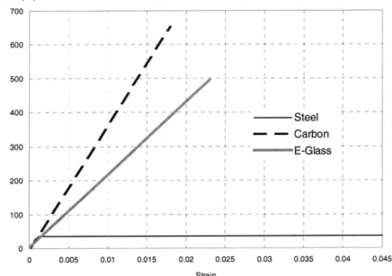
As described in Section 2.2, FRP composites are made of two basic materials - fiber reinforcements and resin matrix. Glass, carbon and aramid fibers are the most commonly used in the construction industry owing to their light-weight, superior tensile strength, and corrosion resistance. Figure 2.1 compares the strength and stiffness of a typical carbon fiber composite, glass fiber composite and construction steel.
I - ---- - - ------ -_/_ - --- - - --- - - - ---- --I - -I-0.005 0.01 0. Steel - - Carbon - E-Glass -- --- --- T-015 0.02 0.025 0.03 0.035 0.04 0.045 Strain
Figure 2.1 Comparison of strength and stiffness of A36 steel, carbon and glass fibers
Epoxies and polyesters are the most popular resins because of their good adhesion capabilities, high toughness, excellent stability and curing properties. In this section, the three types of fiber reinforcements will first be presented, followed by their corresponding forms of existence. Then, the two resin matrices will be examined.
Stress (ksi) 7 0 0 1 600 -500 -400 _ 300 -200 -100 -0 0 do
2.3.1 Fiber Reinforcements A. Glass Fibers
Glass fibers are mainly categorized into E-glass and S-glass. The "E" in E-glass is abbreviated from "Electrical"; the "S" in S-glass is abbreviated from "Structural". In general, E-glass possesses excellent electrical insulation characteristics while S-glass has higher strength and greater corrosion resistance. Both types of glass fibers are calcium aluminoborosilicate formulations. They are inorganic and do not support combustion. E-glass fibers are considered the industry standard and cost less than the S-E-glass fibers. However, S-glass fibers have higher strengths due to their higher alumina content. Typical filament strength and stiffness values are presented in Table 2.1.
Table 2.1 Mechanical Properties of E-Glass and S-Glass Filaments
Properties E-Glass S-Glass
Strength (ksi) 500 670
Stiffness (psi) 10.5 x 10⁶ 12.4 x 10⁶
In spite of their chemical resistance, fire resistance, and high tensile strength, glass fibers have a significant draw back. The fiber surface is prone to moisture attack under certain conditions of exposure and above certain stress levels. This attack normally lead to stress-rupture failure if no remedial measure is provided.
B. Carbon Fibers
Carbon fibers are produced by the thermal decomposition of organic precursor fibers such as rayon or polyacrylonitrile (PAN), followed by a stabilization and carbonization procedure. Other alternative precursors are coal, petroleum, and synthetic pitches. The fabrication involves a spinning process. Tensile strength of PAN-based fibers has always been higher than the pitch-based fibers. Therefore, most carbon fibers today are PAN-based. The most important mechanical properties are elastic modulus, tensile strength, electrical conductivity and thermal conductivity. The typical tensile strengths of carbon
fibers are 600-750 ksi, at the higher end of the S-glass fiber strengths. Some even have strengths as high as 1000 ksi, which are less consumed in the industry because of their production cost. Carbon fibers are in general more brittle than glass fibers. But they show exceptional fatigue resistance. Stiffness is higher than all metals.
C. Aramid Fibers
Aramid fibers are aromatic polyamide formulations that are organic in nature. They can be categorized into two main types - para-aramid and meta-aramid fibers. Para-aramid fibers have higher strength and are normally used in high performance applications. One well-known commercial name for para-aramid fibers is the Kevlar fibers. Due to their highly aromatic and ordered structure, aramids have very high thermal resistance. They do not melt prior to decompositions and do not burn when the flame source is removed, although they can be ignited. Compared to inorganic fibers like carbon or glass, aramid are superior in fire resistance because the fibers themselves do not readily conduct heat into the matrix. The typical decomposition temperature is around 450 C. The typical tensile strength and stiffness are 400 ksi and 15 x 106 psi. The tensile strength is about that of mid-range carbon fibers. One of the major drawbacks is their weak bending and compressive strengths. They easily buckle or kink under compression forces and the fibers damage. Other major drawbacks include the relatively low adhesion to most resin matrix materials, and high moisture absorption by the fibers.
2.3.2 Forms of Fiber Reinforcements
Reinforcing fibers appear in various forms, depending on the end-use application. The fibers can be in the form of either discontinuous fibers (staples) or continuous fibers (filaments). Staples are usually placed randomly within a matrix to attain isotropic properties so that the load resistance in any direction is almost identical. Continuous fiber filaments can be further fabricated into strands and roving. The fiber bundles can then be weaved into fabric cloths with various patterns. In general, fiber strands have higher tensile strength then the fabric counterparts with respect to weight. This is resulted from the unavoidable kinking within the fabric weave. Each form is elaborated below.
A. Staples
Staples are used to form reinforcing mats or surface mats. In some cases, they are used to reinforce concrete materials by direct addition of chopped fibers with concrete during concrete mixing. The products demonstrate isotropic properties because of the random orientation of the short fibers, which have a length of less than 0.02". The fibers enhance load carrying capacities because they take stresses in their direction and prevent cracks in the matrix or concrete from developing and propagating.
B. Continuous Strands
Continuous strands that are used in column winding are made of many single fiber filaments twisted together or made of several untwisted strands that are adhered together chemically. These continuous strands can be pre-impregnated or impregnated on site simultaneously during the winding process. The strands also act as the basic units of woven fabrics. Continuous strand have higher strength than woven fabrics because they are straight and smooth, without any local stress concentration that may exists when stretched in tension (see below).
C. Fabric Cloths and Tapes
Fabric cloths are weaved in patterns that are similar to textile cloths fabrication. The cloths are weaved using continuous fiber strands with specified fiber contents, depending on application and design requirements. Fabric cloths exhibit lower tensile strength because of the kinking at cross points of the weave. When the fabric is stretched under tensile pull, points of stress concentration forms when the fiber roving tends to straighten up. Points of stress concentration then eventually damage the epoxy bonding and form white dots, demonstrating locally highly stressed resin and relative movements of the fiber roving in orthogonal directions. Fabric tapes show similar behavior and they are trimmed to size from fabric cloths. Woven roving are similar to fabric cloths, but are usually made of thicker fiber roving than the twisted fiber strands. Load capacities of woven roving are in general higher than that of fabric cloths.
Comparison of Cost and Thickness
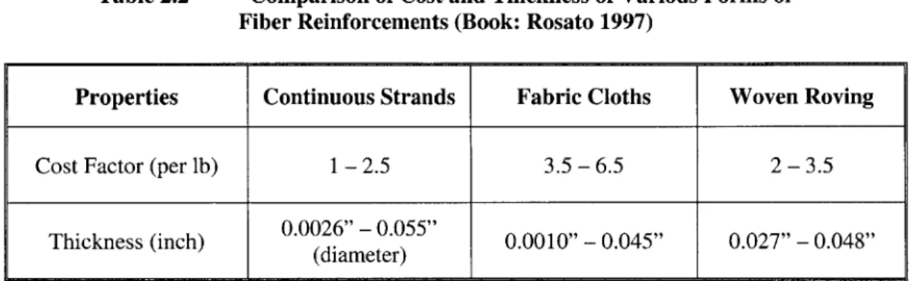
Table 2.2 shows the cost ratios and size ranges of respective forms of fiber reinforcement. It can be noted that the cost of fiber strands for filament winding is the lowest. Cost of cloth fabrics and woven roving are higher because of the extra fabrication procedure and one more level of quality control during the fabric weaving process.
Table 2.2 Comparison of Cost and Thickness of Various Forms of Fiber Reinforcements (Book: Rosato 1997)
Properties Continuous Strands Fabric Cloths Woven Roving
Cost Factor (per lb) 1-2.5 3.5 -6.5 2-3.5
Thickness (inch) 0.0026" - 0.055" 0.0010" - 0.045" 0.027" - 0.048"
(diameter)
2.3.3 Resin Matrix A. Epoxy Resins
Epoxy resins are advantageous in several ways. First, they provide excellent adhesion to a wide variety of fibers because of their inherent polar nature. Second, it has a low level of shrinkage upon curing. Third, there is no release of volatile by-product that causes bubbles or void formation in the curing process. Forth, epoxy has a very high toughness due to their cross-linked structure. Finally, it gives excellent mechanical properties. In view of the many advantages and benefits of epoxy resins, they have been very popular in forming the FRP composites that are used in civil structures. However, epoxy resins have demonstrated a tendency to absorb moisture both in the uncured and cured stage. Also, the elongation to failure is relatively low. The elongation disadvantage has been improved by modified epoxy resin formulations. It was reported that no degradation of the composite materials has been observed even after over 20 years of service exposure (Handbook: Peters 1998). Curing at room temperature and heat accelerated curing are available.
B. Polyester Resins
To date, thermosetting polyester resins are the most widely used of all matrix materials. The thermosetting process consisted of a chemical reaction that cross-links the material so that it cannot be returned to liquid form. At ambient temperatures, the liquid polymers are very stable and can be stored for many months. On the other hand, they can be cured within minutes by adding a peroxide catalyst. Fiberglass reinforced polyester composites in general have excellent mechanical properties and acceptable environmental durability. Comparing with the epoxy resins, polyester resins have a lower cost. However, this resin does not provide adequate adhesion to carbon and aramid fibers. Cure shrinkage is also relatively large. The drawbacks have been deterring its use in the construction industry where carbon and aramid fibers are involved. Curing at room temperature or under heat is available.
2.4 Mechanical Behaviors of FRP Laminates
Mechanical behaviors that will be discussed include behaviors of stress and strain, different orientation, creep, as well as resistances to fatigue and impact. FRP laminates are of major concern. Both isotropic laminates and those with directional properties are examined.
2.4.1 Stress and Strain Behaviors
Stress and strain behaviors can be considered from two perspectives - micro-mechanics and macro-mechanics. Micro-mechanics considers FRP composite materials in the microscopic scale, which considers fiber and matrix as separate entities. Macro-mechanics considers FRP composite materials as in the macroscopic scale, which considers fiber and matrix respond together as one homogeneous material while permits directional properties. Equations in the following subsections that present both micro-and macro-mechanics are extracted from the books of Rosato 1997, Holmes micro-and Just 1983, and Ashbee 1989.
2.4.1.1 Micro-mechanics Representations A. Isotropic Laminates
When chopped fibers are mixed with resin in random orientation, the laminate has directionless properties and can be treated as an isotropic material. The microscopic behaviors are highly complex and normally consist of interfacial debonding and crack development in the matrix material. Crack propagation direction cannot be generally predicted due to the randomness of the embedded short fibers. Therefore, for isotropic laminates, the macro-mechanics approach is often used.
B. Orthotropic Laminates
For orthotropic laminates, with long continuous fibers embedded in the matrix material, clearly defined bonding interface can be identified. Fibers and matrix are considered as separate entities, although they are adhered together and have considerable interactions under load. The stresses and elastic moduli of the respective materials are considered separately and the effects are superimposed to get the resulting or equivalent stress and elastic modulus of the composite material.
Let us consider a simple case where only unidirectional fibers exist in the laminate and the fibers are aligned with the load vector. For a given tensile pull, the following equation applies.
F = c A = f Af + am Am
Such that F = applied force
c= mean stress intensity on entire cross-section A = total cross-sectional area
C,= stress intensity in fiber A= cross-sectional area of fiber
am = stress intensity in resin matrix AM = cross-sectional area of resin matrix
Assuming a perfect bonding initially between the fiber and the matrix, compatibility condition has to satisfy at the fiber-matrix interface. The two entities have to move together. Therefore, the following equation can be derived.
a. Em
cyf Ef
such that Em = modulus of elasticity of resin matrix E, = modulus of elasticity of fiber
Also, the elastic modulus of the composite in the longitudinal direction is given by
E A = EfA + EM Am
where the parameters are defined as before. Since volumetric ratios of the fibers and matrix are directly proportional to their cross-sectional areas, the parameters in the first and third equations that represent the cross sectional areas can be entirely substituted by the respective volumetric ratio parameters Vf and Vm. The total cross-sectional area A can be substituted by unity, which is the addition of the two volumetric ratios that represent fibers and matrix respectively.
2.4.1.2 Macro-mechanics Representations A. Isotropic Laminate
For isotropic laminates, the familiar engineering equations below apply. Isotropic laminate has an identical elastic modulus in any direction. The stress-strain behavior follows the Hooke's law and the Poisson's ratio v is related to the shear modulus G and elastic modulus E in the following way.
G = E 2(1+ v)
Also, direct stress (7, direct strain E, shearing stress t and shearing strain y are related as follow.
E
G
B. Orthotropic Laminate
For orthotropic materials like fabric cloths and weaved roving, the elastic moduli in the longitudinal and transverse directions can be different. Poisson's ratios in the two directions can also differ accordingly and must be determined experimentally. For designs, strains at various arbitrary angles with the applied load are often desirable.
The following presents the relations of the properties of a single-layer laminate in an arbitrary loading direction 1, making an angle x with the longitudinal fiber direction. No shear stress is applied. Superposition methods can be used to determine the resulting stress if more than one load is acted on the laminate, making different angles with the longitudinal fiber direction.
I. Strain Induced in the Direction of the Applied Stress The applied stress c1 causes a strain -1 such that
B1
Ei in which E1 can be determined from the following
El = cos4c+ -sin4 a+ 2LT i2 2
II. Transverse Strain Induced by the Applied Stress A transverse strain 62 that is caused by c-, is
62 = - V12 E1 where V12 = EVLT EL [ 1+2vLT + EL _ GL si 2 c2 } LTET GLT
III. Shear Strain Induced by the Applied Stress
Shear distortion and hence shear strain Y12 will appear in the laminate when the applied stress in the 1-direction acts at an angle other than 0 and 90 degrees with the fiber directions. The shear strain can be found from the following.
712 EL
in which m, can be determined from
+E 1 EL mi = sin2a vT + T 2 COS2a ET 2 GL E
+
vLT L _ L ET GLTIV. Other General Relationships of the Orthotropic Properties
The Poisson's ratios in both the longitudinal and transverse directions are related as follow.
VLT _ EL
VTL ET
And GLT can be determined theoretically from the experimentally obtained data vL, VTL, EL and E from the following relations.
G =ELET
LT EL +vTL)+ET(1+vLT)
It can be noted that the above two formulas can be decomposed back to the isotropic formulas if EL equals ET and that vLT equals VTL.
2.4.1 Orientation Behavior
Mechanical behaviors of FRP composites are dominated by the arrangement and interaction of the fiber reinforcement and the surrounding matrix. As pointed out earlier, if chopped fibers are mixed with the resin matrix, the laminate would appear isotropic due to the randomness of the fibers. However, directional properties occur if the continuous roving is placed in orthogonal directions. The maximum strength should occur in the primary fiber direction. When the load and fiber orientation do not align with each other, significant reduction of structural efficiency is resulted. Figure 2.2 shows a typical strength variation with the angle of loading. The variation is computed from the classical laminate theory using typical properties of E-glass unidirectional laminates.
Strength 270 I I I I I I I I 240 -I I I I I I I I I I I 210 I I I I I I I I I I I I I I I I I I I I I I 180 - - - + - - - - - -I I I I I I I I 150 - I - - - -I I I I I I II I I 120 -I I I I II 91 I I I - I I I 30 -0 0 10 20 30 40 50 60 70 80 90 100 110 120 130 140 150 160 170 180 Angle (Degree) Figure 2.2
Typical strength variation with loading angle in a laminate
Besides the strength difference, failure modes also differ. Unidirectional fibers exhibit fracture upon tensile loading in the fiber direction. The same laminate exhibits resin failure if loaded in the transverse direction because there is no load resisting fibers. Resin-fiber interfacial debonding may occur. If the laminate is rotated to an angle with the applied load, shear plane failure should occur. Fiber may not fracture and the matrix is subjected to substantial shearing stress, a force component decoupled from the tensile pull as demonstrated from the shearing strain equation.
2.4.2 Creep Behavior
Creep behavior is dominated by resin. Creep in the thermoplastic resin matrix is far more substantial than that in the thermosetting resin matrix. Creep experienced is dependent on temperature and the magnitude of the applied stress. The molecular bonds in the resin are strained under a continued application of stress. Responses of these bonds are slow and the state of equilibrium is not reached after a long time. Therefore, the material continues to deform for long periods after application of load. Upon removal of load, unrecoverable deformation occurs. On the other hand, temperature affects the molecular activity. When the temperature is increased, additional creep can be observed. Thermosetting plastic resins such as epoxy are more resistant to the molecular movement by the inherent cross-linking during the curing process. Therefore, creep is less pronounced in thermosetting resins.
2.4.3 Fatigue Resistance
Fatigue resistance of carbon and boron fibers is excellent. The stiff carbon and boron fibers are able to bridge the cracks that occur across the matrix and hence reduce the stress intensity of the crack tip. Fatigue occurs more substantially, however, in glass fiber reinforced plastic composite. Glass fibers are comparatively less stiff and the stress transfer mechanism from the matrix to the fibers is less effectively, making the matrix more prone to large stresses and strains and promoting the crack development under a fewer number of load cycles than carbon and boron fibers. Fatigue tests on fiberglass laminates indicated a deterioration of stiffness, especially at low cycle testing (Handbook:
Peters 1998). It was suggested that the deterioration was due to the creep behavior of the resin matrix.
2.4.4 Impact Resistance
Damage from impact load may reduce the strength of composite laminates, depending on the speed of impact, and the intensity of the impact load. It was indicated from test results (Handbook: Peters 1998) that delamination of the impacted area could be substantial, accompanied by peeling in the direction of the surface laminate fibers. In general, the impact resistance depends on fiber content, weave pattern and weave density. For multi-layer laminate stack up, the resistance also depends on the interlaminate-shearing strength of the resin matrix.
2.5 Environmental Effects 2.5.1 Weathering
In general, weathering capabilities of FRP composites depend highly on the resin matrix characteristics. Degradation can be noted upon extended exposure in outdoor environments. Since the mechanical behaviors such as strength and stiffness are provided almost by the fibers, degradation of the matrix material will not have direct impacts on those behaviors. However, one should remember that the role of matrix is to protect the fibers from micro-crack, moisture attack, as well as to transfer and distribute external loads evenly onto the stress taking fiber reinforcements. Therefore, protection to the matrix is also essential.
Weathering can be in various forms. The most common include ultraviolet (UV) radiation, thermal extremes. UV radiation causes degradation due to molecular weight change and cross-linking decomposition in the resin system. Thermal extremes may occur cyclically in the form of freeze and thaw cycles as well as subjected to high temperatures over a season and low temperature over another. Cyclic thermal fatigue can
occur in such occasions. To tackle these problems, protective coatings have been developed and were found to be effective (Handbook: Peters 1998).
Moisture is known to attack the fibers directly and reduce the original strength through micro-cracking. To tackle the three major weathering problems, protective coatings were developed and were found to be effective in preventing severe degradation of the FRP composite systems under service conditions (Handbook: Peters 1998).
2.5.2 Corrosion
Moisture attack with the presence of oxygen is known to cause severe corrosion in steel. Rusting and cracking of concrete covers are known problems that can hardly be eliminated in the construction industry. Corrosion in FRP composites are found to be minimal, although fibers are prone to moisture attack and can crack prematurely under load. The role of resin matrix is therefore essential in protecting the fibers from moisture attack. Resins developed especially for underwater construction of FRP composites are also developed so that resins cure upon contact with water (Manual: Fyfe 1999).
2.5.3 Flammability
Elevated temperatures due to fire for a prolonged period of time can seriously affect the properties of FRP composites. Matrix softening would occur and is, interestingly, depending on the stacking and humidity. It was found out that quasi-isotropic stacking could effectively reduce the strength reduction at elevated temperature while unidirectional stacking could experience substantial strength reduction. The elevated temperature does not affect only the resin matrix, but also to the fibers, especially the PAN-based fibers. Oxidation was reported from experimental tests for such fibers.
2.6 Retrofit and Strengthening of Reinforced Concrete (RC) Structures 2.6.1 Current Applications and Developments
FRP composite systems find applications in reinforced concrete columns, beams, walls, slabs, chimneys, posts, tanks, and brick or block walls and faqades, as well as structural wood elements. The majority of applications are found in RC structures. FRP systems can be in the form of FRP bar reinforcements, bonded plate systems, two-dimensional grid systems, confinement fabrics, and prestressing tendons. These systems mainly replace the traditional roles of heavy steel reinforcements, jackets, or tendons.
The use of FRP bar and bonded plate systems has gained success and maturity in replacing traditional steel reinforcements and strengthening plates. The use of confinement fabrics especially for column-like structures for strengthening and seismic retrofit has been extensive over the past 5 years and there are signs of increasing use of such technique. By mid 1998, there are well over 120 projects that employed such method (Manual: Fyfe 1999). However, analytical models that can be used to predict stress-strain responses accurately are still lacking. Designs are mostly based on previously developed confinement models that have been successfully applied for steel confinements such as steel jackets or spiral and circular reinforcements.
In view of the weathering and degradation problems of the composite systems, materials such as fire resistant coating, corrosion inhibitors, chemical resistant coating, and UV resistant coating have been developed to apply externally on the composites for protective purposes (Manual: Fyfe 1999).
2.6.2 An Example of the Effect of FRP Retrofit of RC Columns
Although analytical confinement models are not fully developed for FRP composites, it has been shown effective that wrapped RC columns could last longer than unwrapped column in the case of exposed bridge columns that consisted of severely corroded steel reinforcement.
According to a study (Manual: Fyfe 1999), three bridge columns located in FDR Drive near Manhattan Bridge at Corlears Park were extensively cracked because of rebar corrosion. The colunm size was 2' x 4' x 10'. All three columns were repaired with identical procedures with cementatious mortar. Two of the columns were then wrapped with three plies of glass fiber composite fabrics while the third column remained unwrapped. It was found that the unwrapped column cracked again after four years of retrofit while the wrapped columns showed no sign of deterioration.
CHAPTER 3
PRECEDING RESEARCH & STATE-OF-THE-ART
3.1 Introduction
Fiber-reinforced plastic (FRP) confined concrete under static axial, flexural, and cyclic or seismic lateral loads have been under investigation to develop retrofit technologies and new construction methods. Researches have been going on in the last two decades in the United States, Canada, Japan, Singapore, and some other countries. Significant contributions were mainly founded in the past ten years in the US and Japan. This chapter aims to provide a comprehensive review of the major contributions in the framework of FRP confined concrete behaviors under monotonic concentric compression loading. Cylinder tests with normal compressive strength concrete (3500 - 6000 psi) will be focused. No attempt is made to review and discuss topics outside this scope. Also, the review focuses mainly on the development in the North America, because most Japanese research literatures were written in Japanese, which is out of the literacy of the author.
The review that follows is organized into two parts. Major experimental programs will first be presented. Theoretical development will then follow. The two sections are made to remain separate because some researches only contained experimental investigations while some others only focused on theoretical developments. Therefore, research groups do not necessarily appear in both sections. Presentation in respective sections follows the chronological order. Each experimental program will include the aim of tests, materials used, specimen information, FRP confinement mechanism, loading method, failure modes, and the conclusion of what was discovered. A brief comment on what needs to be improved will follow. In the theoretical development section, equations that predict ultimate stress and strain will be presented. In cases where constitutive relations were
developed, the analytical models will also be presented without reproducing the derivation procedures. Finally, a master summary of these advancements and deficiencies will be provided. The logical development and needs of an experimental investigation at MIT will then follow.
3.2 Experimental Programs
The FRP confinement concept in increasing axial strength and ductility of a concrete column is originated from the characteristics of concrete subjected to triaxial stress states. In fact, this confinement concept has been utilized in the form of spiral and circular reinforcement and steel and concrete jacketing in strengthening and retrofitting reinforced concrete columns and bridge piers since decades ago. The use of FRP as the confinement jacket reflects the advancement of materials over time while the fundamental concept remains. This fundamental confinement concept was pioneered in 1927 in University of Illinois under the directions of Richart et al. They formulated a linear analytical model for the prediction of ultimate load (Richart 1928), forming the foundation of all subsequent model developments. With this in mind, there is a need to first review this important initial investigation on triaxial stressed concrete so as to provide more insights on the subsequent findings particularly on FRP confinement such as failure modes and analytical model developments.
3.2.1 Richart, Brandtzaeg and Brown (1928, University of Illinois) Objectives
The objective of the experimental program was to obtain information on how the ability of concrete to resist stress in one direction was influenced by the presence of stresses in the other directions. It aimed at investigating the validity of a general conception of the process of failure and thus developing a failure mechanism conception for optimal proportioning for strength and durability.
Experimental Particulars
Altogether three series of specimens were produced. The first series contained cylinders subjected to simple axial load and two-dimensional compression respectively. The second series consisted of cylinder subjected to three-dimensional loading with the axial load larger than the lateral compression. The third series had the cylinders subjected to three-dimensional compression with the axial load smaller than the lateral compression. Cylinders sizes of 4" x 8" and 4" x 22" were used. Normal strength plain concrete with lean, medium, and rich mixtures were used. Axial compression was carried out in a testing machine. Lateral compression was produced by oil pressure through a hand pump. The two load types were applied simultaneously. Obviously, active lateral confinement was provided. Vertical load was applied to the specimens with displacement control at a rate of 0.05 in. per minute. Sets of dials were used for displacement measurements.
Findings and Conclusions
It was discovered that the added strength produced by a given lateral pressure was near constant, regardless of the concrete mixtures being studied. Lateral deformation near maximum load was found to have radical increase. Material internal continuity was rapidly being destroyed after that critical state. A wide range of deformation occurred with little change in the accompanying load beyond the maximum load. Most cylinders were still intact when removed from the loading chamber while a few were seen to have developed inclined surface cracks.
It was concluded that the results agreed fairly well with the results of a preceding series, in which spirally reinforced concrete was used. The increase in the ultimate strength produced by the passive lateral pressure developed by the spiral reinforcement was equal to 4.1 times the lateral pressure. The law of resistance was considered essentially the same for concrete restrained by lateral oil pressure, as for concrete spirally reinforced, although lateral confinement was active in the first case while passive in the latter case.
Comments
Although the tests were simple, they have established the fundamental conceptions on the behavior of freshly made concrete under multi-axial compression in terms of failure modes, and ultimate loads with respect to the lateral pressure applied. It is, in fact, quite important to have identified the comparable behaviors and quantitative relationship of concrete under active and passive confinement pressures.
3.2.2 Fardis and Khalili (1981, 1982, Massachusetts Institute of Technology) Objectives
Fardis and Khalili conducted an early experiment of its kind, using the FRP encasing technique. They aimed at finding out the feasibility and efficiency of this new construction method. This concept was pursued in view of the excellent tensile strength and advantageous properties of FRP, and the drawbacks commonly found in steel jacketing. Such drawbacks include the high weight-to-strength ratio, labor-intensive installation procedure, and steel corrosion problem for exposed structural members. They proposed to simplify the composite system construction procedure by using FRP as a permanent formwork as well as the strength enhancing material.
Experimental Particulars
Concrete cylinders were encased in continuous glass fibers weaved in orthogonal directions (vertical and horizontal). Wrapping instead of encasing was actually performed due to the constraint of available products. Cylinder sizes were 3" x 6" and 4" x 8". Normal strength concrete (4500 - 5500 psi) with water/cement ratio 0.55 was used. Four types of FRP were used. They included balanced weave, unbalanced weave, and unidirectional fibers. Balanced weave implies that the fiber content in one direction is identical to those in the other direction. Circumferential fibers were intended to provide lateral confinement while longitudinal fibers took up tension caused by any unanticipated bending effect. All cylinders were tested under a monotonic, concentric, axial load. Load control mechanism was used at a rate of 20 - 50 psi/sec.