In
HAB
Prof
nstitut
S
P
BIB ISSA
f. Dr. Jos
Supér
Struct
Param
Proje
A MATTO
eph MOR
ieur de
tural
Flex
metric
et de Fin d
OS Franci
RLIER (IS
e l’Aéro
Optim
xible
c Mod
d’Etudes /
July 20
isco (ISA
SAE / DM
onautiq
miza
Wing
del A
Final Yea
011
AE Supaer
MSM)
que et
tion o
g:
Appro
ar’s Thesis
ro / ITA)
de l’Es
of a
oach
s
space
Abstract
The following work presents a parametric model approach for the optimization of a flexible wing aiming the improvement of the reduced model developed in parallel to this study. At first, how to create a complex metallic Wing-Box model for single aisle commercial aircrafts is demonstrated, following what big manufactures such as Airbus and Boeing use in theirs products, and developing a full parametric PCL code in Patran. Then, an optimization processes is presented using the Nastran Design Sensitivity and Optimization algorithm, also known as Sol200.
The main objective is to optimize the global structure weight respecting all structural criteria and constraints, and using the spars and skin thickness as design variables. After the optimization, the importance of upper and lower skins is minimized and almost all efforts are concentrated on spars, specially the rear spar. It’s also shown that the strain criterion is stronger than the stress one, which considers shear and buckling as the critical design points, although fatigue is also relevant when designing the lower Wing-Box Skin.
This computational model allows the determination of all Wing-Box element thickness that give the minimum wing weight, helping the preliminary design task to achieve the optimized structure in the shortest time, enhancing the results by the lowest costs possible. Associating this work with an aerodynamic approach using CFD would make possible to create a variation of the required profile to construct the real wing that, when deformed, would assume its best shape in terms of aerodynamics, still respecting all structural constraints and minimum weight possible. Finally, another important approach consists of doing the exactly same study but with composite materials, since the future of aviation may reside no more in metallic alloys, but in composites.
Table of Contents
TABLE OF VARIABLES AND CONSTANTS ... 5
1 - INTRODUCTION ... 7
1.1-DMSMISAE/SUPAERO ... 8
1.2-INTERNSHIP OBJECTIVES ... 9
1.3-NASTRAN OPTIMIZATION ... 9
2 - MODEL AND DEVELOPMENT ... 10
2.1-PATRAN ... 11 2.1.1 - Wing Geometry ... 12 2.1.2 - Materials ... 16 2.1.3 - Properties ... 16 2.1.4 - Boundary Conditions ... 19 2.1.5 - Load Case ... 19 2.1.6 - Meshing ... 25 2.2-NASTRAN ... 26 2.2.1 - Sol200 ... 29 2.2.2 - Analysis ... 31 2.2.3 - Design Variables ... 31
2.2.4 - Criteria and Constraints ... 32
2.2.5 - Design Optimization Parameters ... 34
3 - RESULTS ... 36
3.1-NON-OPTIMIZED WB(PART I) ... 37
3.2-WB OPTIMIZED BY STRESS CRITERIA ONLY (PART II)... 39
3.3-WB OPTIMIZED BY STRESS,STRAIN AND MAX.DISPLACEMENT CRITERIA (PART III) ... 48
4 - CONCLUSION ... 57
5 - REFERENCES ... 59
ANNEX 1 - MORE OPTIMIZATION RESULTS FOR PART II (8 NACA PROFILES) ... 62
ANNEX 2 - NUMERICAL RESULTS FOR PART II OPTIMIZATION ... 67
ANNEX 3 - NUMERICAL RESULTS FOR PART III OPTIMIZATION ... 71
Table of Variables and Constants
gj Inequality Constraints hk Equality Constraints xi Side Constraints X Design Variables b Wingspan S Wing Area AR Aspect Ratio λ or ε Taper Ratio δ Dihedral Λ ¼ Chord Sweep
θ Wing Tip Torsion
MTOW Maximum Takeoff Weight
m Maximum Camber
p Maximum Camber Position
t Maximum Relative Thickness
E Young’s Modulus
ν Poisson Ratio
ρ Density
Ti Cartesian Translation (i= x, y or z coordinate)
Ri Cartesian Rotation (i= x, y or z coordinate)
nz Critical Load Factor
nzce Extreme Load Factor
Cm or Cmprofil Profile Moment Coefficient
Y Normalized Position along Spanwise
L Total Lift
Va Aerodynamic Speed
Cz Lift Coefficient
g Gravity Acceleration
S(Y) Total Shear Force
Sa(Y) Shear Force due to Aerodynamic Efforts
Sm(Y) Shear Force due to Inertial Efforts
Ba(Y) Bending Moment due to Aerodynamic Efforts
Bm(Y) Bending Moment due to Inertial Efforts
T(Y) Total Torsion
Ta(Y) Torsion due to Aerodynamic Efforts
Tm(Y) Torsion due to Inertial Efforts
C Local Chord
Cr Root Chord
Mwing Wing Mass
Mfuel Fuel Mass
Mmot ou Mm Engine Mass
Ym Engine Position along Spanwise
lCG_CS Distance between Gravity Center and Shear Center
dF Vertical Distance between Engine Center of Thrust and Shear Center
dM Horizontal Distance between Engine Center of Mass and Shear Center
F Engine Thrust
σcomp Compression Stress
(σcomp)cr Critical Compression Stress
τxy Shear Stress
(τxy)cr Critical Shear Stress
ηs and ηc Plasticity Reduction Factor
Ks Buckling Coefficient due to Shear
Kc Buckling Coefficient due to Compression
t Thickness
ts Thickness for Local Buckling
fty Maximum Distortion Energy Yield
σvm Von Misses Stress
dytip Wing Tip Displacement
1 - Introduction
This Final Year’s Thesis is intended to give a parametric approach to a flexible wing optimization for the Osycaf Project. This entire study is directly correlated to the reduced model developed by Assis Lima [1], which provides the inputs and post-processing for the results of this work, by its Surrogate Model.
The main objective is to structurally optimize a Wing-Box for commercial aircrafts, providing the lowest weight for the entire structure that resists to all loadings and boundary conditions, respecting the parameters constraints and conditions that define a real wing, according to manufactures such as Airbus, Boeing, Embraer and Bombardier.
To create the Wing-Box, PCL code was used as default, with the help of MSC Patran 2007, which consists of a strong GUI tool to design complex structures to be after analyzed in Nastran. The first part is then to create the wing based on parameters such as span, chord sweep, taper ratio, tip torsion, dihedral and a given profile. This is extremely important to allow changing the entire wing just by changing the parameters and running the PCL code once more, without the need to reconstruct everything from the beginning.
After this, the boundary conditions are implemented, as well as the loading case that is based on complex aerodynamics and inertial models. The geometry is then meshed and materials and properties added, generating a modeled structure ready to be exported as bulk data by Patran to Nastran.
With all elements generated, the optimization process starts using Sol200 in Nastran, a Design Sensitivity and Optimization algorithm. The Executive Control deck is defined as well as the Case Control Deck and the Bulk Data. In this moment, the stress, strain and displacement criteria are added and the constraints applied. The variables are chosen and the optimization parameters adjusted.
Running Sol200, the optimized Wing-Box configuration is returned in terms of thickness of every section of the Wing-Box spars and skins. The global weight is the objective design for minimization and the new wing presents the lightest configuration that respect all structural criteria and constraints, keeping wing geometry, properties and materials.
1.1 - Aero deve indus Mate Mech core form dyna secon comp Figure 1 - F
DMSM I
The Dep onautics and loping meth stry by its erials and hanics. DMSM subjects o mations. Stru amic and the ndly the us ponents. Final Wing-BSAE / Sup
partment of d Space (D hods and to 4 axes: D Structures, also covers of general uctures, par ermal analy se and qual Box NACA 24paero
f Structural DMSM/ISA ools for desi Damage of Vibratory s the scienti mechanics rticularly th ysis, leading ification of 420 model in Mechanics AE), in Tou ign of aeros Composite y Dynamics ific discipli s and cont he thin one g one hand o f metallic s static analys s and Mate ulouse - Fr space struct Aerospace s and Adv nes related tinuum for es, are the s on the certif structural m is - displacem erials of the rance, focu tures, and m e Structures vanced Nu to solid me Supaero a subject of d fication of a materials and ment translat e Superior us on resea meets best th s, Fatigue o umerical M echanics in and Ensica developmen aerospace st d composit ional. Institute of arching and he needs of of Metallic Methods for ncluding the a academic nt in static, tructure and e structural f d f c r e c , d l
1.2 - Internship Objectives
One of the objectives of this internship is providing a reasonable approach to structural modeling in Patran and optimization and design sensitivity in Nastran. This research and development aim to be a direct response for the reduced model also proposed by the same project. In this way, the numerical optimization results shall be used to validate and improve the analytical equations developed for preliminary design of future aircraft programs. It is important to remember that even numerical solutions are still expensive, and reducing costs is fundamental for competitive industries.
Another objective is to provide all tools and academic support for a Final Year’s Thesis, which represents the last step on an engineering graduation program. The parametric approach and structural optimization using Sol200, on the other way, represents only a small part in a much bigger project named Osycaf. This program started on April 2010 and goals the optimization of a coupled fluid-structure representing a flexible wing - structural and aerodynamics optimization, in other words. The Osycaf Project is a partnership between ONERA, ISAE, IMT, CERFACS and STAE Toulouse.
1.3 - Nastran Optimization
The Sol200 is the Design Sensitivity and Optimization algorithm for Nastran based
on gradient methods and used in this study. To understand its functioning, a few concepts must be established. The basic optimization problem statement is usually to find X that minimizes, or maximizes, the F(X) objective subjected to:
g X ≤ 0 j = 1, … , n inequality constraints (1)
h X = 0 k = 1, … , n equality constraints (2)
x ≤ x ≤ x i = 1, … , n side constraints (3)
are d of de searc conv prese may
2 - M
spar, based Fami profi conse In this n designated u The obje esign variab ch. The ine vention, that ent, must be either be linModel a
The obje , rear spar, d on comm ily or Boein ile will be c equently ch otation, item using a lowe ective functi bles. Side c equality con t is, a cons e satisfied e near or nonand Deve
ective of thi upper skin, mercial meta ng 737 Fam hanged man hange the w Figure 2 -ms that are er case symb ion is the sc onstraints a nstraints ar straint is sa xactly at th linear functelopment
is study is th , lower skin allic wing, s mily. But for ny times an ing area (an- Complete N in upper ca bol with a s calar quanti are placed o re expressed atisfied if it e optimal d tions of the
t
he optimiza n, corner st similar to th r the study, nd this impli nd so the sp NACA 2415 wase are vect subscript to ity to be min on the desig d in a less ts value is design. The design vari ation of a W tiffeners and hose found a totally pa ies on a lifti an) to keep wing model re ors while m indicate the nimized. It gn variables s than or e negative. E objective an ables. Wing-Box co d skin strin in aircrafts rametric wi ing coefficie total lift.
eady for analy
members of e member. is a functio s to limit th equal to zer Equality con nd constrain omposed by ngers. It’s a s such as A ing is desire ent change, ysis. the vectors on of the set he region of ro form by nstraints, if nt functions y ribs, front a Wing-Box Airbus A320 ed since the , which will s t f y f s t x 0 e l
the w reduc
2.1
Elem Nastr 2007 know • • • • • • • two d elem The propu a reu Initially wing skin ced model.- Patran
Patran i ment Analys ran, Marc, 7 was used a To defin wn as the pr Wingspa Aspect R Taper Ra Dihedral ¼ Chord Wing Ti Profile (N It’s also different typ ments will b static load ulsion and i The entir usable sessio a complete was suppre Figure 3 -is the worl sis (FEA), Abaqus, L as GUI inter ne a wing 1 rofile, are ne an (b) or Wi Ratio (AR) atio (λ) l (δ) d Sweep (Λ) p Torsion ( NACA 4-D necessary t pes of alum e used. For d is chosen inertial forc re wing is c on that can e wing was essed so th - Final Wing-ld’s most providing s LS-DYNA, rface for Na dimensiona eeded. The ing Area (S ) θ) Digits Series to define the minum are th r the bound n to be theces and mom constructed u be run by P created, inc he model re -Box NACA 2 widely use solid mode ANSYS an astran. al + 5 non-d inputs are, t S) s) e materials he materials dary conditi maneuver ments. using PCL Patran to rec cluding its epresents e 2420 model re ed pre/post ling, meshi nd Pam-Cra dimensional then:
and the pro s chosen and ons, a fixed loading ca code. This construct th skin. For th exactly wha
eady for anal
t-processing ing, and an ash. For thi parameters
operties in t d for the pro d wing – ca ase and co is extremely he model aft he final stu at is propo lysis. g software nalysis setup his study, M s and the cr the wing. In operties she antilever – oncerns aer y important fter changin dy, though, osed by the for Finite p for MSC MSC Patran oss section, n this study, ell and bean is adopted. odynamics, t to compile g just some , e e C n , , n . , e e
param with boun skin. studi be pr sessi file.
2.1.
will b numb dista Airbu consi meter - var aid of mac ndary condit As menti For the stu ied in the re rocessed sin ion is finaliz1 - Wing G
The wing be the same ber of ribs, ance betwee us and Bo idered to be Fi riable declar cros in Mic tions, prope ioned, a com udy, the wi educed mod nce the win zed, the numGeometry
g desired is e along the fixed to 29 en ribs kept oeing for al e linearly di gure 4 - Spac ration. The crosoft Exc erties, mater mplete wing ing skin wa del, which i ng skin con merical mody
s based on s entire wing 9 and equall to around 0 lmost all o istributed al cing of ribs in code has m cel. Runnin rials and me g was progr as suppress is just the W ntains a gre del is conve some design g - constant ly spaced. T 0.6m / 2.0 f of theirs ai long span. n civil transpo more than 1 ng the sessi eshing takes ramed at firs ed, so that Wing-Box. T at number erted to Nas n restriction t profile cro This means ft, which is irplanes. Th ort wings - B 16.000 lines on to creat s no more th st - complet the structur This also gi of nodes an stran langua ns. The first oss section. 28 wing se the medium he third is oeing and Ai s, and was te geometry han 8 minut te Wing-Bo ure is exactl ives a lighte nd elements age by Patra t one is that The second ections, with m distance that wing irbus [17]. programed y, loadings, tes. ox and wing ly the same er model to s. After the an, in a .blk t the profile d one is the h a medium adopted by g torsion is d , g e o e k e e m y sprofi to be • • • • • Some • • • • MTO lift c varia dime span In this pr ile changing e known: Aspect R Taper Ra Dihedral ¼ Chord Wing Ti e of the airc MTOW Fuel Ma Engine M Engine T The win OW when in oefficient, w able, and de ensional par goes aroun Figu roject some g in the glob Ration = 9.5 atio = 0.16 l = +5° d Sweep = 2 p Torsion = craft charac = 55000 Kg ass = 18000 Mass = 2500 Thrust = 184 g area / win n constant h which is dif efining the p rameter. Fo nd 32 meters ure 5 - Wing e parameters bal structur 5 25° = -3° teristics we g Kg (total) 0 Kg (each) 415.9 N (ea ng span mu height fligh fferent for e profile impl or this class s, so even v composed by s were fixed re. The non
ere also fixe
) ach) ust attend th ht - cruise. B each profile. lies in a co s of airplan very differen y 29 ribs equa d to allow a -dimension d: he total lift But total lif . In this way rrespondent nes (MTOW nt airfoils sh ally spaced. a deeper stu al paramete required th ft is also a y, the profil t wing area W around 5 hould stay a udy on the i ers were kep
hat is a func function of le was chose a / wing spa 55000 Kg), around this nfluence of pt constant, ction of the f the profile en to be the an, the only total wing value. f , e e e y g
For the profile and objective of this study, the NACA 4-Digits Series was chosen since its analytical equations allow inserting the entire profile as a variable when programing. This NACA Series has 3 parameters:
• Maximum camber (m)
• Maximum camber position (p) • Maximum relative thickness (t) The NACA 4-Digits Series equations are:
= 2 − = 0 = (5) = 1 − 2 + 2 − = = (6) ± = . 0.2969√ − 0.1260 − 0.3516 + 0.2843 − 0.1015 (7) = − sin (8) = + cos (9) = + sin (10) = − cos (11) = tan (12)
The NACA 4-Digits Series also has a special notation: NACA ABXX has A for the maximum camber in %; B is for maximum camber position in % times 10; XX is for maximum relative thickness in %, about the chord. For example, a NACA 2412 means 2% maximum camber, 40% maximum camber position and 12% of maximum relative thickness.
camb the fr Wing const ribs, ratio dispo comp step, Figur With the ber and afte front spar w g-Box is 40 tant. With the the basic p , chord sw osition. Wi plete frame and they ar Figur NAC NAC re 6 - Examp ese equation er, these po would be at 2 0% of chor Figure 7 - W e basic profi profile was eep, dihedr ith all ribs, is ready to re created fo re 8 - Comple CA 0012 CA 5412 20% les of NACA ns, 40 poin ints were sp 20% of cho rd length in Wing-Box sp file, it is now s scaled, tra
ral and tors , lines to s o give suppo orm the edg
te wing geom 4-Digits Seri nts were ge plined to cr ord length, a n each sec pars located a w possible t anslated and sion, respec support the ort to all th ge curves or metry generat ies automatic nerated for reate the pr and the rear tion of the at 20% and 60 to start the d rotated, a cting so eve e stringers e rest of the r from trimm ted by param 60% cally generate r upper cam rofile contou r spar at 60% wing, and 0% of local c wing creati accordingly ery single d and stiffen e geometry. med curves. metric PCL co NACA 2412 NACA 2315 ed in Patran. mber and 40 ur. It was d %. This me d this meas chord.
ion. For eac y to aspect
dimension ners are cre
. Surfaces a .
ode in Patran
0 for lower defined that ans that the ure is kept
ch of the 29 ratio, taper and spatial eated, so a are the next
. r t e t 9 r l a t
2.1.2 - Materials
The materials adopted are the same usually found in metallic single aisle aircrafts of the big manufacturers. In this study, they are the aluminum alloys Al 7150 T7751 and Al 2024 T351 Bare, with homogeneous and isotropic properties, so Young’s modulus (E), Poisson ratio (ν) and density (ρ) are the 3 parameters that matters - the Shear modulus G is computed directly from the equation E = 2·(1+ν)/G. The Al 7150 T7751 is used in the upper Wing-Box skin, upper corners stiffeners and upper Wing-Box skin stringers. The Al 2024 T351 Bare is used in the lower Wing-Box skin, lower corners stiffeners, lower Wing-Box skin stringers, front spar, rear spar and ribs. The properties are:
• Al 7150 T7751: E = 71.016 GPa, ν = 0.3 and ρ = 2823 Kg/m3. • Al 2024 T351 Bare: E = 73.774 GPa, ν = 0.3 and ρ = 2768 Kg/m3.
Nastran translate these materials in the form of MAT1 that defines the material properties for linear isotropic materials.
2.1.3 - Properties
When studying a Wing-Box, buckling, shear and bending stress are important to be analyzed. In this way, for the skin, spars and ribs the 2D property Shell was chosen, which is translated in Nastran as a PSHELL card that defines the membrane, bending, transverse shear, and coupling properties of thin shell elements. The only geometric parameter is thickness, which will also be the optimization variable for Sol200.
For stiffeners 1D beam elements were chosen. For Nastran, this is the PBEAML element, which defines the properties of a beam element by cross-sectional dimensions, and in this case is L-shaped. For stringers 1D bar elements were chosen. For Nastran, this is the PBARL element, which defines the properties of a simple beam element (CBAR entry) by cross-sectional dimension, and in this case is Z-shaped.
only DVP and L accur and s diffe is im whic algor Figure 9 - L After stu possible w PREL1 card L shaped b racy - no in In this p shear mom rence betwe mportant, the ch is the c rithm usuall Figure 10 - C L and Z shap udying the S with a linea ds. This mea beans, only nside parame roblem, it i ents, but no een open an e simplest b circular one ly returns n Circular shap
ped beam cros
Sol200, it w ar relation o ans that no one of its eters associ is considere ot torsion. S nd closed se beam cross e. Note tha on accurate
ped beam cro
ss-section, pr was revealed of design v complex g 4 paramete iations poss ed that the s Since only ections, and section wa at for com e results whe oss-section us rimarily selec d that chang variables an geometry ca ers could be ible. stiffeners an the torsion d for the res as chosen fo mplex beam
en offset is
sed for stiffen
cted for stiffen
ging the pro nd geometri an be chang e changed, nd stringers analytical t the cross s or the contin m cross sec defined.
ners and strin
ners and stri
operties of a ical parame ged entirely still withou s support on formula co section area nuation of ction the o ngers in final ngers. a material is eters, using y, and for Z ut complete nly bending onsiders the a that really the project, ptimization model. s g Z e g e y , n
desig stiffe cross area toget appli a lin initia beam case to res The circu gn variable eners and st s sectional a as the 14 u ther must b ied for the l near approx al condition Figure For Nast m element (C is a circula spect the W ular cross s and this rad tringers cro area by the upper skin s be the sam lower skin a imation wa ns provided b e 11 - Final w tran, this is CBAR entr ar ROD cros Wing-Box ex section has dius defines oss sectiona following w stringers; an me as the u and strips. S as also used by the redu ing-box confi also a PBA ry) by only ss section. T xternal geom only the ra s all cross s al areas are way: the 2 nd the total upper Wing Since Nastra d to associ uced model, iguration: sk ARL eleme one cross-s The model s metric boun adius as inp ection prop directly as upper corn l area of up g-Box skin an doesn’t a ate skin an which chan
kins, spars, sti
ent, which d sectional dim studied also daries. ut, so a sin erties. As a sociated wi ers stiffener per stiffene area. The accept DVP nd strips are
nge for each
iffeners, strin defines the mension - t o presents th ngle relation a project def ith the Win
rs must hav ers and upp
same corre PREL2 for t ea relations h NACA pro
ngers and rib
properties the radius - he correct b n between a finition, the ng-Box skin ve the same er stringers elations are this neither, s, based on ofile. s. of a simple and in this eam offsets a e n e s e , n e s s
2.1.4
nece this i [ 0 , 0 Fig2.1.5
this s consi impo decid mom thick exist atmo consi FAR of al cente4 - Bound
Since the ssary to res is done by a 0 , 0 ] and [ gure 12 - Boun5 - Load C
What co study, the m idered. Thi ortant cases ded to keep ment, so dis kness constr ts and must In this st ospheric con idered to be R25.303 is n Another ll forces an er to the shedary Condi
e studied W strict all tran a SPC1 card [ R1 , R2 , R ndary conditCase
oncerns the maneuver in is is the m s are landin the MTOW sregarding raint will a not be igno tudy, cruise nditions ar e nz = 2.5 an nzce = 3.75. considerati nd moments ear center, aitions
Wing-Box co nslational an d that define R3 ] = [ 0 , 0tions for cant
load cases, n altitude w ost critical ng and cras W but consid its presence also be take ored. e Mach is 0 e assumed. nd the secur ion is that th s. In this w and the same
omes from and rotationa
es a set of si 0 , 0 ] appli
tilever wing: z
, for the pre with MTOW load case sh. To go der empty fu e provides en into acco 0.79, cruise . For mane rity factor is he shear cen way, all iner e for the aer
a cantilever al degrees o ingle-point ed to the fir zero translati eliminary d W and cruise when desig a little fart fuel wings b an even m ount since altitude is euver in alt s 1.5, so the nter was cho rtial forces rodynamic r wing, fixe of freedom constraints rst rib surfac
ion and rotat
design, just e speed will gning the w ther on the ecause fuel more critica industrial te 12500 mete titude, the e extreme lo osen to be th were transl forces on th ed on the fu in its root. with [ T1 , ce. tion on first r a few are r l be the onl wing struct case adop l alleviates t al situation. technologic ers (41000 critical loa oad factor a the point of lated from he aerodyna uselage, it’s In Nastran, T2 , T3 ] = rib surface. relevant. In y load case ture - other pted, it was the bending . Minimum limitations ft) and ISA ad factor is according to application the gravity amic center. s , = n e r s g m s A s o n y .
With bend aerod the f bend distri torsio is no = so: = comb h this it is p ding momen dynamic lift A deeper final equati ding momen ibution. The on is conse ormalized by ⁄ The total = The resu bination or Figu = + = + = + possible to nts and all ft, it was dis r mathemat ions are sh nt and torsio e shear effo equence of t y the half w l lift is also = ∙ ultant forces aerodynami ure 13 - Shea + + + resume all l torsion m regarded in ical and phy hown in thi on are taken orts and bend
the profile m wingspan, wh considered ∙ s, applied o ic and inerti ar force, bend vertical fo moments. Si n this analys ysical appro is section. n into accou ding mome moment co here B is th d to be equa on the shear ial forces: ding moment orces to just ince drag i sis, so no ho oach is pres About the unt. The lift ent derive fr efficient Cm he wingspan l to the wei r center of e and torsion a t one result is usually l orizontal for sented by E aerodynam was approx om this ellip m. The non-n, so: ght times th each Rib at applied on sh tant, as wel less than 1 rce is presen Elodie Roux mic load, s ximated to a iptical distri -dimensiona he extreme Y position hear center. ll as for all 1/17 of the nted. [8], so just shear force, an elliptical ibution, and al approach (13) load factor, (14) , are than a (15) (16) (17) l e t , l d h , a
equa The follo For the a ations are: = ∙ ∙ = ∙ ∙ = owing pictu Figure 14 -aerodynami 1 − ∙ ∙ ∙ ∙ ∙ ures better d - Aerodynam c load, whe √1 − − 1 − ⁄ ∙ ∙ ∙ describe each mic efforts at m ere ε is the p ∙ sin − ∙ ∙ − 1 1 h term invo maneuver in profile max − ∙ √1 − − + olved: altitude load ximum relati − − sin − 1 1 − d case. ive thickne + 1 − ss, the final (18) (19) − (20) l
engin its m value than Figure 15 For the i ne, which is mass and th es where th Ym. The fin 5 - Inertial eff inertial and s an elemen hrust are im he first is fo nal equation
forts and due
d engine loa nt that chan mportant and or Y before ns are: e to the engin
ads, two cas nges totally d considere e the engine ne thrust at m ses must be the shear, b ed. The last
e position Y maneuver in a e considered bending and t term of e Ym, and the altitude load c d: before an d torsion ef each equatio e second fo case. nd after the fforts, since on has two r Y greater e e o r
− √1 − − span nacel mete bend F probl the d every rotati wing was desig just v = ∙ = − ∙ − − sin = _ 1 1 − For aircr . Since the lle and supp ers and dM ding due to i Figure 16 - D Another lem is also distance betw y single rib ion. For the g mass, win created. Ac gned in Ma variables de + ∙ ∙ ∙ − ∙ ∙ ∙ ∙ ⁄ + rafts with w studied wi port the eng
= 3.43 me its mass. Distances betw important c considered ween the gr b, a large ese paramet ng area / wi ctually, sinc tlab environ eclaration, a ∙ ∙ 1 − ∙ ∙ ∙ 0 + ∙ ∙ wing mounte ing has 29 gine. The en eters from t ween thrust a consideratio to be ellipt ravity cente group of p ters, such as ng span, ch ce the nume nment and all provided ∙ ∙ √1 − + ∙ ∙ ∙ − 0 ed engines, ribs equally ngine’s cen the wing’s and weight po on is the fue tical, althou er and the s parameters s shear cent hord root, a erical mode all paramet d by it. − − sin ∙ ∙ 1 − ∙ ∙ 1 − ∙ the usual Y y spaced, th nter of thrus shear cent oints of applic el distributi ugh in the e hear center is changed ter and grav a direct inte el is an opti ters come fr n − ⁄ − ∙ ∙ ∙ √1 − Ym position he 10th rib st is conside ter, and cau
cation and th ion along w nd zero fue . In this par d due to sc vity center p rface with t imization re from it, the
∙ 0 ∙ ∙ − − sin n is at 1/3 o was chosen ered to be a uses local t he wing shear wingspan, w el is admitte rametric mo caling, tran position, Cm the reduced esponse for first PCL c ∙ (21) ∙ (22) + ∙ (23) of half wing n to fix the at dF = 1.30 torsion and r center. which in this ed. lCG_CS is odeling, for slation and mprofil, initial d model [1] this model code part is g e 0 d s s r d l ] l s
force that vecto a sta entrie Fi unrea calle degre freed distri In Nastr e at a grid p define a sta or that deter atic load as es. igure 18 - Rig Since it al situation d Rigid Bo ees-of-freed dom that ar ibute the co Figure 17 ran, forces point by sp atic concen rmines the d a linear co
gid Body Elem
was decide would be st ody Elemen dom that ar re specified oncentrated 7 - Final load are translat ecifying a v ntrated mom direction. T ombination o ment REB2 u d to apply t tudied. To s nt, or RBE re specified at an arbit load to the case applied ted as FOR vector. The ment at a gr The loading of load sets used to distrib
the load dis solve this p E2 card, wh d at a single trary numbe entire mode to wing-box RCE cards e moments rid point by case is grou s defined v bute punctua stribution o roblem, Na hich defines e grid point er of grid p el, and so ha model in Pat that define are translat y specifying uped in a LO ia FORCE, al efforts to en n the shear stran has an s a rigid bo t and with points. With ave a more tran. e a static co ted as MOM g a scale fa OAD card t , MOMENT ntire wing-bo r center of e n extremely ody with in dependent h this, it is realistic sol oncentrated MENT cads factor and a that defines T and other ox section. each rib, an y useful tool ndependent degrees-of-possible to lution. d s a s r n l t -o
2.1.6
mesh comp was elem prope thick since woul sectio F6 - Meshin
For the m h. In optimi putational w implement ments is also When th erty is only kness of a s e the analyti ld give n dif on has 15 e Figure 19 - Long
meshing of ization prob work, but a ted to give a really sim he optimiza y possible i shell would ical bucklin fferent flux lements - d oad distribut the Wing-B blems, incre coarse me e total cont mple work a ation proce f it has onl d only return ng formulati . In this way efined by th Figure 2ted along win
Box, a conv easing mesh sh also pre trol over th and doesn’t ess in Sol20 ly one elem rn descent r ion presum y, each spar he 2 stiffene 20 - Final win gspan with a vergence stu h refinemen vents good he refinem take more t 00 started, ment. This m results if th mes constant r section ha ers and 14 s ng-box mesh r id of REB2 e udy was ma t usually re results. A ent so cha than a few s it was fou means that c e shell didn flux, and n as only one e tringers. refinement. elements. ade to have esults in a m parametric anging the seconds. und that op creating a v n’t have a n elements i element, an the lightest much harder mesh seed number of ptimizing a variable for refinement, in one shell nd each skin t r d f a r , l n
For the 1D bar property, the Nastran translation for elements is CBAR. For the 2D shell, a Quad is the element shape, IsoMesh is the chosen mesher and Quad4 in the topology configuration. This means that all spars and skin elements are rectangles with the edge length controlled by the mesh seed. Nastran translates this by CQUAD4 elements that define an isoparametric membrane-bending or plane strain quadrilateral plate element. The ribs were meshed by paver that means irregular trapezoidal shapes.
All parameterization, even for the mesh, is extremely important since every studied wing has a completely different geometry (only dimensional parameters are kept constant). About geometry, 4 main input parameters change as well as hundreds of secondary parameters. About the properties, each section has 4 defined different skin thickness and 4 stringers and stiffeners geometrically correlated radius, and since there are 28 sections, at least 112 thickness are inputs that changes in every wing. With this amount of variables, a not all parameterized wing would cost and inestimable time spend in Patran, something absolutely not desirable.
2.2 - Nastran
Nastran is the world's most widely used Finite Element Analysis (FEA) solver. When it comes to simulating stress, dynamics, or vibration of real-world, complex systems, Nastran is still the best and most trusted software in the world. In this project, MSC Nastran 2007 is used for structural optimization. As presented before, the optimization process is based on equality and inequality constraints, side constraints and design variables, all associated by structural algorithms and processed by the optimizer.
the D is a u the a nece respo synth to th proce sensi perfo The figu Design Mod The initi unique featu analysis fu ssary to pe onses can be hesize these The conc he process t ess. Accura itivity and o orming sens ure below sh del for Sensi
Figure 21 - M ial design is ure of the D nction. Ho erform mu e created by e results wh cept of Con that is used ate sensitivi optimization sitivity analy hows how a itivity and O MSC / MD N s a combina Design Sensi wever, for ltiple types y a number en performi nstraint Scre d to identify ity analysis n. The indiv ysis and the
all these con Optimizatio Natran implem ation of the itivity and O design se s of analys of analysis ing its redes eening is int y those con s is the hal vidual analy ese are deve
nstraints and on. mentation of S analysis mo Optimizatio nsitivity an ses. This r types and i sign. troduced in nstraints tha lmark of N ysis types ea eloped in De d variables a Structural Op
odel and the n capability nd optimiza reflects the it is necessa structural o at are likely Nastran imp ach have th esign Sensit are used in Optimization [ e design mo y. Structural ation, it is fact that ary for the o optimization y to drive th plementation heir own tec
tivity Analy developing [3]. odel, which l analysis is frequently the design optimizer to n and refers he redesign n of design hniques for ysis. g h s y n o s n n r
For the optimizer, Nastran uses a variety of optimization algorithms from the MSCADS suiteof algorithms as well as the IPOPT algorithm. The IPOPT algorithm is a special purpose optimization algorithm to address design tasks with a large number (> 3000 to 4000) of design variables and has its primary application to topology optimization tasks, but can be also applied to the conventional design tasks as well. Its access requires a Topology Optimization license. The IPOPT algorithm is open source code available from COIN-OR and maintained by IBM. It implements an interior point line search filter method. Structural optimization has also introduced the Approximate Model concept that involves the construction of high-quality approximations to the finite element results so that the number of full scale finite element analyses is kept to a minimum.
The Improved Design is the point at which the finite element model is updated based on the results from the optimizer so that a new finite element analysis can occur. Design Optimization is an iterative process and a key part of the implementation is therefore determining when to stop the iterations and set as converged. Tests for convergence discuss the many factors that enter into making this decision.
As for Discrete Variable Optimization, an underlying assumption of the Design Sensitivity and Optimization capability Nastran is that the variations in the design variables are continuous and that therefore the responses and their sensitivities are also continuous. Practical engineering considerations frequently dictate that values of the designed properties be chosen from a discrete set.
Finally, the Topology Optimization is a special version of design optimization that finds an optimal distribution of material, given package space, loads and boundary conditions. Basically, it makes a design variable out of each finite element that can vary from 0 (remove) to 1 (keep) and the algorithm strives to force real design variables to one of these limits. In this project Topology optimization will not be approached.
2.2.
really langu secon macr gene struc The E • • • The C • • • • • • •1 - Sol200
The Sol2 y large num uage that re ndary progr ro may be rating the . ctured the fo Executive C TIME: m SOL 200 CEND: i Case Contro ANALY TITLE: t MAXLIN DESOBJ DESGLB PARAM BEGIN B0
200 doesn’t mber of var espects som ram is requ useful, but .bdf file, w ollowing wa Control Dec maximum ex 0: design se indicates th ol Deck is r YSIS: the typthe algorith NES: define J: select a d B: select the M, X: contro BULK: ind t have a GU riables (up me rules and uired, since t usually M which has m ay: ck indicates xecution tim nsitivity an e end of the responsible pe of analys hm title is gi e the maxim design variab e constraint l the output icates the en UI interface to 12 mill d presents N the code us Matlab or E more than 1 what type o me allowed; nd optimizat e Executive for controll sis (STATIC iven; mum numbe ble as the o ts to be resp t for post-pr nd of the C e in Patran ions) and c Nastran uni sually exce Excel is us 1.000 lines of solution. ; tion solution Control. ling the exe CS, DFREQ er of output bjective fun pected; rocessing; ase Control , since it’s constraints. ique cards. eds thousan sed. In this s. A Nastra n; cution of ta Q, BULK, M lines; nction; l. designed to It also has To write in nds of lines s project, E an bdf file i asks. MODES, etc o support a s a specific n Sol200, a s. A Python Excel aided is basically c.); a c a n d y
any i by S grid, Sol20 decla this s The Bulk information ol101 trans elements, 00. After d ared, and fin specific stud k Data is w n associated slated by Pa materials, declaring th nally the de dy, the entir
Figure 22
where all ele d to the mod atran to Na properties, he model, th sign optimi re process in 2 - MSC / MD ements, var del and its s astran in the , loadings he unique S ization para n represente D Natran Sol2 iables, cons solution are e form of a and bound Sol200 des ameters in th ed by the fo 200 Design M straints, mat e declared. T bdf file. Fr dary condit ign variable he form of a ollowing dia Modeling Proc aterials, prop The model rom this fil tions are im es and con a DOPTPRM agram. cess. perties, and is obtained le, only the mported to nstraints are M card. For d d e o e r
2.2.2 - Analysis
The analysis proposed is based on a static load, and the main objective is to optimize the entire Wing-Box according to buckling and maximum shear stress criteria, strain criterion and maximum wing tip displacement. With a cantilever wing, given the load case, it’s possible to calculate the minimum thickness for each part respecting the structural constraints. A global optimization will find the best thickness combination that will reduce the Wing-Box weight to a global minimum.
2.2.3 - Design Variables
The chosen independent design variables are the section shell thickness of each structure, and this means 4 structures (upper and lower skins, front and rear spars) in each of the 28 sections, so 112 design variable. In Nastran, this is programed by a DESVAR card, which defines the design variables to be used in design sensitivity and optimization. Design sensitivity analysis computes the rates of change of design responses with respect to changes in the design variables. In design optimization, the set of design variables are the quantities modified by the optimizer in the search for an improved design. The optional DESVAR Case Control command can be used to specify the set of DESVAR Bulk Data entries that are to be used in the design task.
The upper WB corner stiffeners and upper WB skin stringers also received a design variable each, as well as the lower ones. This means 4 more variables for each section, but these 112 variables are dependent of the 56 WB skin thickness variables. This is possible through DLINK cards that relate one design variable to one or more other design variables by linear relation. The linear relation, in this case, is based on the area distribution between WB skin, stiffeners and stringers, as mentioned before.
The design response that will be globally optimized is the total weight, and Nastran has already a specific entry in DRESP1 card for this action called WEIGHT. The total of design variables is so 224.
2.2.4
criter comb Whe uppe stres altho boun so 15 of th4 - Criteri
The Upp ria used are bination of + re: = = About th er skin Al 7 ses in both ough it’s conThe par ndaries for l 5 segments e local wing Figu
a and Con
per Skin pre e than the compressio ≤ 1 hese equatio 7150 T7751 skin bound nsidered to ameter b i local buckli compose th g chord, app ure 23 - Wingnstraints
esents comp material yi on and bucki ons, ηc = 1. 1 is used, s ary surfaces be a thin sh is the dista ing. The Wi he Wing-Bo proximately g-Box configu pression str ield and locing criteria: 0 and ηs = so E = 71.0 s, so in this hell. ance betwe ing-Box ski ox chord. In y. uration inside
ress and she cal buckling : 1.0; Kc = 4 016 GPa an s study an av en 2 conse in is divided n this way, b e the wing us ear stress as g. The equa 4.0 Ks = 5.4 nd ν = 0.3. verage was ecutive stri d by 14 stri b is conside sing NACA 44 as critical st ation in thi 4 and ts = 0 . Nastran p taken to be ingers that ingers and 2 ered to be 1 420 profile. tresses. The is case is a (24) (25) (26) 0.5t. For the rovides the etter results, define the 2 stiffeners, /15 of 40% e a e e , e , %
The Lower Skin presents tension stress and shear stress as critical stresses. The criterion used is than the maximum distortion energy yield, so the Von Misses Criterion was adopted. The equation is so:
≥ 1 (27)
For the Al 2024 T351 Bare, used in the lower skin, fty = 290.0 MPa, and the Von
Misses stress is given directly by Nastran, so it’s not necessary to calculate it by analytical formula. The Von Misses used is also an average of both provided by Nastran.
The Front and Rear Spars presents the same behavior, so the exactly same approach was adopted for both structures. The critical stress is the shear stress, and the shear criterion was adopted. The equation is:
≥ 1 (28)
Where:
= (29)
In this case, ηs = 1.0 and Ks = 5.4. For the upper skin Al 2024 T351 Bare is used, so E
= 73.774 GPa and ν = 0.3. Nastran provides the shear stresses in both skin boundary surfaces, so an average was again taken.
Another criteria adopted is the maximum wingtip vertical displacement that shall not pass 1,7 meters. In fact, for Airbus A320 wing, the destructive test shows a maximum deformation of 2,5 meters, and considering a safety marge of 50%, the adopted value is acceptable. This is a criterion also used in aeronautical industry for psychological aspect, since a huge wing deformation may cause panic between passengers.
The strain criterion is also taken into account. For modern aluminum alloys, the limit is around 4 micro deformations, so:
−4 ∙ 10 ≤ ≤ 4 ∙ 10 (31)
In Nastran Sol200 language, a DTABLE card defines a table of constants to be used in conjunction with DEQATN equations. A DRESP1 card defines direct, or first-level, analysis responses to be used in design sensitivity and optimization. The responses identified here are those which are directly available from the analysis results as opposed to second-level responses which are defined using DRESP2 and DEQATN entries. This means all stress, strain, displacement or any output given directly from Nastran structural calculus will be given in a form of DRESP1.
The DRESP2 card defines equation responses that are used in the design process, either as constraints or as an objective. It’s in this type of card that the criteria are inserted, with aid of a DQATN card that defines equations for use in synthetic relations. These equations can be used to define either second-level responses or second-level design variable-to-property relations. The constraints limits are imposed by DCONSTR cards that places limits on a design response. When selected in Case Control by either DESGLB or DESSUB, the DCONSTR sets define the design constraints. Finally, the relation between an analysis model property and design variables is made by DVPREL1 cards.
2.2.5 - Design Optimization Parameters
There are numerous parameters that control various aspects of the optimization process itself. While all of these parameters have defaults (the DOPTPRM entry is optional), the defaults may be changed using the DOPTPRM card entry which overrides default values of parameters used in design optimization.
There are three types of approximation methods to choose from in Sol200: direct linearization, mixed method, and convex linearization. The mixed method is the default but in this study, the direct linearization (APRCOD = 1) will be used. It’s based on the simple first-order Taylor series expansion directly in terms of the design variables. The method is often useful for dynamic response optimization, shape optimization, and optimization tasks that use basis vector formulations.
The optimization process is iterative since the optimizer obtains data about the design space from approximations. The approximate model, constructed based on a detailed finite element analysis, is used by the optimizer to find an approximate optimum. This design is resubmitted for another finite element analysis followed by another approximate optimization. This process is repeated until convergence with respect to these overall design cycles is reached or until the maximum specified number of design cycles (DESMAX) is reached. In this problem DESMAX was adjusted to 50.
As the optimizer modifies the design variables, the structure’s properties and/or shape will vary depending on the design model description. Move limits need to be placed on the approximate sub problem for efficiency reasons and these move limits are imposed with respect to analysis model properties as well as design variables. They can be changed from their defaults by modifying DELX for design variables, which defines rational change allowed in each design variable during any optimization cycle, and was set to 0,5.
The parameter CONV1 is used to test for overall design cycle convergence. It is the Relative criterion to detect convergence. If the relative change in objective between two optimization cycles is less than CONV1, then optimization is terminated. This parameter is used in connection with tests for both hard and soft convergence. Tests for Convergence describe the types of convergence testing as well as the convergence decision logic. Soft convergence compares the design variables and design properties output from the approximated model optimization with these same values at the beginning of the design cycle. Hard convergence testing compares the analysis results of current design cycle with those of the previous cycle. This test is a more conclusive test of convergence since it is based on hard evidence. Hard convergence will always terminate the design cycle process.
The DELOBJ defines maximum relative change in objective between ITRMOP consecutive iterations to indicate convergence at optimizer level, and was set to 1.0E-3. The ITRMOP defines the number of consecutive iterations for which convergence criteria must be satisfied to indicate convergence at the optimizer level, and was set to 3.
The relative change in objective attempted on the first optimization iteration is controlled by DOBJ1. Used to estimate initial move in one-dimensional search, it is adapted as the optimization progresses, and is set to 0,1. The minimum move limit imposed by DPMIN is 0,01, and the minimum design variable move limit impose by DXMIN is 0.05. The constraint normalization factor GSCAL used is 1.0E-3, and finally the optimization METHOD adopted is the Modified Method of Feasible Directions for both MSCADS and DOT.
3 - R
on on locat struc 25% 3 par and l FiguResults
In order ne Wing-Bo ted at 40% cturally supp chord swee rts: Part I: S Box base Part II: approach Part III: means o criteria. All three loading case ure 24 - Stres to better ex ox only. Th % of chord ports a 38, ep of 25°, olution base ed on the in Optimizati h of the Red Optimizat ptimizing th e studies ar e. Part I is h ss tensor in St xplore the o he chosen pr d and with 3 meters sp dihedral of ed on the R nput parame on in Sol2 duced Mode ion in Sol2 he Wing-Bo re based on held directly tatic Solution optimization rofile is the h 12% max pan wing, w f 5° and win Reduced Mo eters, withou 200 with o el, serving s 200 based ox respectin n a Static S y by Sol101 n of a Wing-B n capabilitie e NACA 242 ximum rela with 9,5 of ngtip torsion odel propert ut any optim nly stress so as a respo on the 3 c ng stress, st olution, wi . Parts II an Box using NA es, a deeper 20, with 2% ative thickn f aspect rati n of 3°. Thi ies input, w mization. criteria, us onse for it. criteria initi train and m th the same nd III are op ACA 2420 pro r study was % of maxim ness. This io, 0,16 of is study is p which means sing exactly ially propo maximum di e boundary ptimized by ofile - bucklin s performed mum camber Wing-Box taper ratio, presented in s the Wing-y the same osed, which isplacement y conditions Sol200. ng response. d r x , n -e h t s
3.1 - Non-Optimized WB (Part I)
In this first part, the NACA 2420 Wing-Box was directly constructed from the inputs provided by the Reduced Model, which means without any optimization. The spars and skins thickness are based on an analytical model that considers only the stress criteria and all calculus were made on Mathlab environment. The 112 inputs were inserted in Patran PCL code without any processing, and the model analyzed by Nastran Sol101.
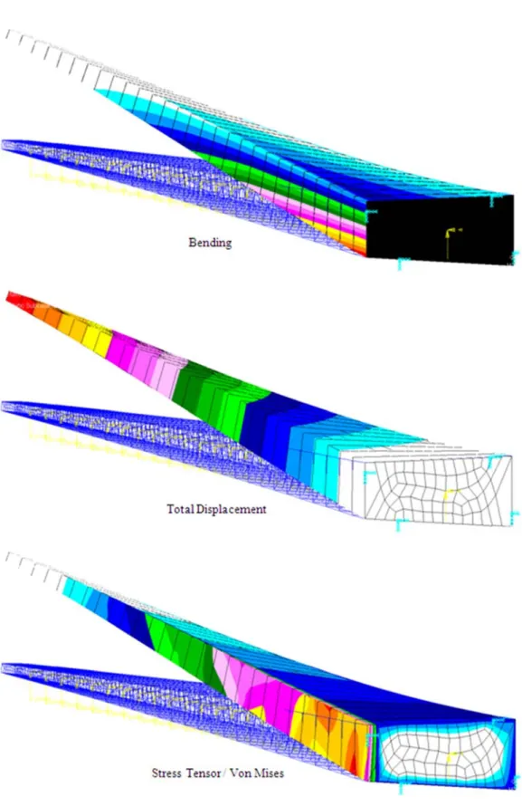
The results show a Wing-Box of 2091,83 Kg (total mass, including skin, spars, ribs and strips). The maximum vertical wing tip displacement is 2,008 meters, which is a huge displacement for a semi-wing of only 19 meters, and the shear stress in shell elements arrives up to 2,5 GPa that overpasses the resistance of any metallic material possibly used in a wing. The following pictures show the bending, total displacement and stress tensor on the deformed Wing-Box (real scaling).
The first and last pictures show that stress is not well distributed along span, and it’s visible that the wing tip is not supporting any efforts (painted in white). The Total Displacement picture gives the real wing tip displacement dimension, which might not tolerated by aerodynamics since lift vector starts to have an important horizontal component. Note that these pictures are presented only for quantitative analysis and comparison with the following analysis, and the Upper Skin and Rear Spar are the visible parts.
Figuure 25 - Bendding, Total Diisplacement a w
and Stress Te without optim
ensor for NA mization.
3.2 - WB optimized by Stress Criteria only (Part II)
In this second part, the Wing-Box was optimized by Sol200 based on only stress criteria, as presented before. This approach is a response for the Reduced Model [1] that uses these results for its Surrogate Model. The 112 thickness variables were redefined to give the minimum global weight respecting all constraints. The other 112 stringers and stiffeners variables were also redefined accordingly to the area relations that define its dependency to the thickness variables. For the NACA 2420, optimization took 18 cycles to converge, and the mass reduction can be seen on the picture below.
Figure 26 - Mass optimization for NACA 4420 profile WB, Static Analysis optimized by Sol200 with stress criterion only, 18 cycles total.
After the 18 cycles, the results converge to a weight of 1805,88 Kg, that is a total reduction of 13,7% or 286 Kg on each semi-wing, a considerable amount in terms of aeronautics. Just to have an idea, the total weight reduction of 572 Kg is more than the total crew weight specified by FAR Part 25, for this class of transport aircraft (A320 and Boeing 737-800). The following table presents the mass in each cycle. The initial mass was 2091,83 Kg. 1500 1700 1900 2100 2300 2500 2700 0 2 4 6 8 10 12 14 16 18 20 Mass [Kg] Cycle
Naca 2420 Mass Optimization
Weight x Cycle
Table 1 - Mass optimization process in Sol200 for the 18 cycles with stress criterion only for NACA 2420 profile WB, in Static Analysis. Initial Weight 2091.83 Kg.
Cycle 1 2 3 4 5 Total Mass [Kg] 2027,34 2424,46 2437,31 2439,26 2434,34 Cycle 6 7 8 9 10 Total Mass [Kg] 2295,56 2207,87 2147,50 2038,73 1994,06 Cycle 11 12 13 14 15 Total Mass [Kg] 1866,19 1873,71 1832,16 1833,08 1801,77 Cycle 16 17 18 - - Total Mass [Kg] 1813,02 1806,55 1805,88 - -
Now the optimization results will be presented for each of the four aimed parts: Front Spar, Rear Spar, Upper WB Skin and Lower WB Skin. Each part presents 28 sections (series on the legend), and for each one the thickness optimization for each section will be presented (for the 18 cycles) and also the final thickness along span, before and after optimization.
Figure 27 - Front Spar thickness optimization for the 28 sections in Sol200 with stress criterion only for NACA 2420 profile WB, in Static Analysis, 18 cycles total.
0,0 0,5 1,0 1,5 2,0 2,5 3,0 3,5 4,0 4,5 5,0 5,5 6,0 6,5 7,0 0 2 4 6 8 10 12 14 16 18 20 Thickness [mm] Cycle
Front Spar Thickness Optimization
Series1 Series2 Series3 Series4 Series5 Series6 Series7 Series8 Series9 Series10 Series11 Series12 Series13 Series14 Series15 Series16 Series17 Series18 Series19 Series20 Series21 Series22 Series23 Series24 Series25 Series26
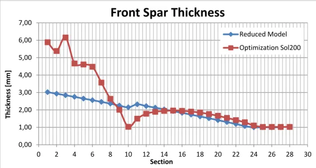
Figure 28 - Front Spar thickness before and after optimization in Sol200 for the 28 sections with stress criterion only for NACA 2420 profile WB, in Static Analysis.
For the front spar, thickness decreases up to the 10th section, just before the engine.
From the 11th section to the 17th it increases again and then decreases to the minimum
thickness. Globally it’s visible that the optimization increased the thickness distribution
before the 10th rib, showing that the engine affects greatly the front spar, being decisive when
designing this part of the Wing-Box. 0,00 1,00 2,00 3,00 4,00 5,00 6,00 7,00 0 2 4 6 8 10 12 14 16 18 20 22 24 26 28 30 Thickness [mm] Section
Front Spar Thickness
Reduced Model Optimization Sol200
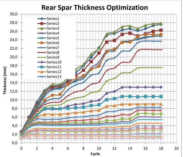
Figure 29 - Rear Spar thickness optimization for the 28 sections in Sol200 with stress criterion only for NACA 2420 profile WB, in Static Analysis, 18 cycles total.
Figure 30 - Rear Spar thickness before and after optimization in Sol200 for the 28 sections with stress criterion only for NACA 2420 profile WB, in Static Analysis.
0,0 2,0 4,0 6,0 8,0 10,0 12,0 14,0 16,0 18,0 20,0 22,0 24,0 26,0 28,0 30,0 0 2 4 6 8 10 12 14 16 18 20 Thickness [mm] Cycle
Rear Spar Thickness Optimization
Series1 Series2 Series3 Series4 Series5 Series6 Series7 Series8 Series9 Series10 Series11 Series12 Series13 0,00 5,00 10,00 15,00 20,00 25,00 30,00 0 2 4 6 8 10 12 14 16 18 20 22 24 26 28 30 Thickness [mm] SectionRear Spar Thickness
Reduced Model Optimization Sol200
For the rear spar, on other hand, optimization increases strongly the thickness of every
section up to the 25th. The first 4 sections has even an increase of thickness by the order of 10
times, showing that in terms of a globally optimized structure, the rear spar is not well designed by the analytical model. It’s important to remember that the numerical solution considers the interaction between all elements of the model, and so the response may be extremely different than expected. After optimization, the rear spar is totally different than the initial structure, but still the engine influences the design process, since greater thickness
increment can be found before the 10th rib.
Figure 31 - Upper WB Skin thickness optimization for the 28 sections in Sol200 with stress criterion only for NACA 2420 profile WB, in Static Analysis, 18 cycles total.
0,0 1,0 2,0 3,0 4,0 5,0 6,0 7,0 8,0 9,0 0 2 4 6 8 10 12 14 16 18 20 Thickness [mm] Cycle
Upper WB Skin Thickness Optimization
Series1 Series2 Series3 Series4 Series5 Series6 Series7 Series8 Series9 Series10 Series11 Series12 Series13 Series14 Series15 Series16 Series17 Series18
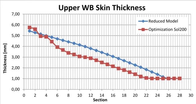
Figure 32 - Upper WB Skin thickness before and after optimization in Sol200 for the 28 sections with stress criterion only for NACA 2420 profile WB, in Static Analysis.
The behavior of the upper WB skin is completely different from the spars. In fact the optimization doesn’t change much the section thickness, and the final results follow not by far the initial design. But in this case, the overall thickness decreases, and the engine influence is not visible. Almost 30% of the upper WB skin rests with the minimum 1,00mm thickness.
0,00 1,00 2,00 3,00 4,00 5,00 6,00 7,00 0 2 4 6 8 10 12 14 16 18 20 22 24 26 28 30 Thickness [mm] Section
Upper WB Skin Thickness
Reduced Model Optimization Sol200
Figure 33 - Lower WB Skin thickness optimization for the 28 sections in Sol200 with stress criterion only for NACA 2420 profile WB, in Static Analysis, 18 cycles total.
Figure 34 - Lower WB Skin thickness before and after optimization in Sol200 for the 28 sections with stress criterion only for NACA 2420 profile WB, in Static Analysis.
0,0 1,0 2,0 3,0 4,0 5,0 6,0 7,0 8,0 9,0 10,0 0 2 4 6 8 10 12 14 16 18 20 Thickness [mm] Cycle
Lower WB Skin Thickness Optimization
Series1 Series2 Series3 Series4 Series5 Series6 Series7 Series8 Series9 Series10 Series11 Series12 Series13 Series14 Series15 Series16 Series17 Series18 Series19 Series20 0,00 1,00 2,00 3,00 4,00 5,00 6,00 7,00 0 2 4 6 8 10 12 14 16 18 20 22 24 26 28 30 Thickness [mm] SectionLower WB Skin Thickness
Reduced Model Optimization Sol200
Finally, for the lower WB skin, optimization decreases hugely the overall thickness, and 70% of all sections receive minimum thickness. It’s visible that after the optimization, the importance of the lower skin is minimized when considering only stress as criterion, and that is why industry such as Airbus uses fatigue as main design criteria for this structure, instead of stress.
The following pictures show the bending, total displacement and stress tensor on the deformed Wing-Box (real scaling). The maximum vertical wing tip displacement is now
0,412 meters, 77% less than for the non-optimized wing. This reflects the importance of
optimization since, in the end, a lighter Wing-Box was generated, with better distributed stress along span, maximum stress respecting the material constraints and a maximum displacement reduced significantly, as may be desirable by aerodynamic constraints. Actually, the maximum displacement criterion isn’t usually active when designing a wing, and exists just for a critical reason.
The Total Displacement picture gives the real wing tip displacement dimension, which is much more reasonable than for the non-optimized metallic Wing-Box. Note that these pictures are presented only for quantitative analysis and comparison with the other analysis, and the Upper Skin and Rear Spar are the visible parts.
Figu rear only 4420 NAC ure 35 - Bend As seen, spar, minim stress as cr 0 and 4430 CA 2420 in ding, Total Di o , the optim mizing the s riterion. Mo are presen Part II are p isplacement a optimized by ization proc skin and res ore general nted in Ann presented in and Stress Te Sol200 with cess gave s sulting in a results for N nex 1. Th n Annex 2. ensor for NA stress criteri significant a better Win NACA 241 he numerica CA 2420 pro on only. importance ng-Box desi 5, 3415, 44 al results fo ofile WB, Stat e to spar, sp ign, when c 415, 2420, 2 or the optim tic Analysis pecially the considering 2520, 2620, mization of e g , f
3.3 - WB optimized by Stress, Strain and Max. Displacement Criteria (Part III)
In this third part, the Wing-Box was optimized by Sol200 based on stress, strain and maximum vertical wing tip displacement criteria, as presented before. This approach is the most complete one, although it does not include the fatigue criterion for the lower WB skin. The 112 thickness variables were redefined to give the minimum global weight respecting all constraints. The other 112 stringers and stiffeners variables were also redefined accordingly to the area relations that define its dependency to the thickness variables. For the NACA 2420, optimization also took 18 cycles to converge, but requested more computational efforts than for Part II. The mass variation can be seen on the picture below.Figure 36 - Mass optimization for NACA 2420 profile WB, Static Analysis optimized by Sol200 with stress, strain and max. displacement criteria, 18 cycles total.
After the 18 cycles, the results converge to a weight of 2454,59 Kg, that is an augmentation of 17,3%. The following table presents the mass in each cycle. The initial mass is 2091,83 Kg. 1500 2000 2500 3000 3500 4000 4500 5000 0 2 4 6 8 10 12 14 16 18 20 Mass [Kg] Cycle
Naca 2420 Mass Optimization
Weight x Cycle
Table 2 - Mass optimization process in Sol200 for the 18 cycles with stress, strain and max. displacement criteria for NACA 2420 profile WB, in Static Analysis.
Initial Weight 2091.83 Kg. Cycle 1 2 3 4 5 Total Mass [Kg] 2633,28 3265,29 3888,67 4532,37 4460,57 Cycle 6 7 8 9 10 Total Mass [Kg] 3430,04 3873,92 2494,49 2269,92 2408,90 Cycle 11 12 13 14 15 Total Mass [Kg] 2349,77 2468,64 2469,77 2461,85 2459,99 Cycle 16 17 18 - - Total Mass [Kg] 2456,55 2454,59 2454,59 - -
The exactly same stress criteria as for Part II was used, and the maximum vertical wing tip displacement was of only 0,128 meter, much inferior than the 1,7 meters established by the displacement criteria. Since there was still a mass and rigidity augmentation, it’s evident that the strain criterion was decisive when optimizing the structure. The maximum
strain adopted was 4.10-3, which is a value allowed only for the best aluminum alloys
available nowadays, and increasing this limit would imply on a non-realistic wing.
Now, as for Part II, the optimization results will be presented for each of the four aimed parts: Front Spar, Rear Spar, Upper WB Skin and Lower WB Skin. Each part presents 28 sections (series on the legend), and for each one the thickness optimization for each section will be presented (for the 18 cycles) and also the final thickness along span, before and after optimization.
Figure 37 - Front Spar thickness optimization for the 28 sections in Sol200 with stress, strain and max. displacement criteria for NACA 2420 profile WB, in Static Analysis, 18 cycles total.
Figure 38 - Front Spar thickness before and after optimization in Sol200 for the 28 sections with stress, strain and max. displacement criteria for NACA 2420 profile WB, in Static Analysis.
0,0 1,0 2,0 3,0 4,0 5,0 6,0 7,0 8,0 9,0 10,0 11,0 12,0 13,0 14,0 15,0 16,0 0 2 4 6 8 10 12 14 16 18 20 Thickness [mm] Cycle