HAL Id: tel-00592269
https://tel.archives-ouvertes.fr/tel-00592269
Submitted on 11 May 2011HAL is a multi-disciplinary open access archive for the deposit and dissemination of sci-entific research documents, whether they are pub-lished or not. The documents may come from teaching and research institutions in France or
L’archive ouverte pluridisciplinaire HAL, est destinée au dépôt et à la diffusion de documents scientifiques de niveau recherche, publiés ou non, émanant des établissements d’enseignement et de recherche français ou étrangers, des laboratoires
Self-organized surface relief gratings in azo-polymer
thin-films
Sohrab Ahmadi-Kandjani
To cite this version:
Sohrab Ahmadi-Kandjani. Self-organized surface relief gratings in azo-polymer thin-films. Atomic Physics [physics.atom-ph]. Université d’Angers, 2007. English. �tel-00592269�
Université d’Angers Année 2007
UFR Sciences N°d’ordre : 804
Laboratoire POMA
Réseaux de surface auto-organisés dans les films minces
d’azo-polymères
THESE DE DOCTORAT
Spécialité : Physique
ECOLE DOCTORALE D’ANGERS
Présentée et soutenue publiquement
Le : 12 October 2007
à : l’Université d’Angers
par : Sohrab AHMADI KANDJANI
Devant le jury ci-dessous:
Rapporteur, Jacques DELAIRE, Professeur, Ecole Normale Supérieure de Cachan Rapporteur, Stanislaw H. KUCHARSKI, Professeur, Wroclaw University of Technology, Pologne
Examinateur, Pascal ROYER, Enseignant-chercheur, Université de Technologie Troyes Examinateur, Habib TAJALLI, Professeur, University of Tabriz, Iran
Examinateur, Régis BARILLE, Professeur, Université d’Angers
Examinateur, Sylvie DABOS-SEIGNON, Chargée de Recherches, Université d’Angers Examinateur, Christophe HUBERT, Maître de Conférences, Université Jean Monnet
Directeur de thèse, Jean-Michel NUNZI, Professeur, Université d’Angers
Co-encadrant: Régis BARILLE, Professeur, Université d’Angers
Laboratoire des Propriétés Optiques des Matériaux et Applications, UMR CNRS 6136, Université d’Angers, 2 Bd Lavoisier, 49045 ANGERS
Abstract
Nature is a beautiful combination of patterns. Natural patterns are self-organized. Well defined self-organized patterns also can appear in laboratory conditions for different systems. In this thesis we present pattern formation via self-organization of azo molecules under light illumination. Illuminated azo molecules undergo a trans-cis-trans photoisomerization and diffuse in the polymer film far from brightness. We show that it is possible to form spontaneous patterns on the surface of azo-polymer films under coherent light exposure. The pattern orientation depends on light polarization and polarization multiplexing for more than two states is possible. The experimental results for different incidence angle are fitted by a simple theoretical model based on stimulated Wood’s anomalies. Various patterns were inscribed by varying input beam polarization and incidence angle. Under incoherent beam illumination, diffusion of azo-molecules is random (no correlation between them) and it is impossible to create a well defined pattern. Presence of an additional low power coherent beam causes pattern formation. Information about formed pattern in the coherent region, propagate in a self-organized manner and cover whole region of incoherent beam. Only a few percent of informed molecules is enough for self-organization. In addition, we also studied light induced birefringence and surface relief grating formation in a series of azo-polymers. Some possible applications of these patterns are presented.
Résumé
Dans cette thèse, je présente la formation de structures utilisant l’auto-organisation de molécules azo. Lorsqu’elles sont éclairées par la lumière, ces molécules subissent une photoisomérisation trans-cis-trans et bougent dans le film mince polymère loin des zones éclairées. Je montre qu’il est possible de former des structures spontanées sur la surface des films azopolymères (réseaux de surface) sous éclairement d’une lumière cohérente. L’orientation de la structure dépend de la polarisation de la lumière. Différentes structures peuvent être inscrites en faisant varier la polarisation du faisceau d’entrée et l’angle d’incidence. Les résultats expérimentaux pour différents angles d’incidence sont expliqués en utilisant le formalisme théorique des anomalies de Wood. D’autre part, sous illumination d’une lumière incohérente, la diffusion des molécules azo est aléatoire et il n’y a pas de corrélation spatiale entre elles. En revanche, la présence d’un faible faisceau de lumière cohérente additionnel permet de former un réseau de surface. L’information alors, inscrite sur la région éclairée par le faisceau cohérent se propage de manière auto-organisée et couvre la totalité de la région éclairée par le faisceau incohérent. Seules quelques pourcents de molécules ayant reçu de l’information suffisent à générer l’auto-organisation. Une dernière partie concerne la biréfringence photo-induite et la formation d’un réseau de surface dans une série d’azopolymères. Quelques applications possibles de ces structures sont présentées.
Acknowledgments
I will always recall with fondness my four-year stay in Angers. It has truly been a privilege and rewarding experience to work in the creative atmosphere of the group of Prof. Dr. Jean-Michel NUNZI. First and foremost I would like to thank him for his continuous guidance, support and encouragement and for being an inexhaustible source of ideas and inspiration. Without him this work would have been impossible to accomplish. He also taught me several other things aside from physics. His compassion and kindness makes me realize how lucky I am to have him as my advisor.
I am grateful to Prof. Régis BARILLE, who gave me expert guidance, generous professional support and invaluable ideas. Apart from being my co-advisor he became my best firend. Meny thanks to him for the translation of the abstract and for carfully reading of manuscript. I am deeply indebted to Dr. Sylvie DABOS-SEIGNON. She was very kind to me and always concerned about my and my family well-being. Also she introduced me to AFM mesearment technique. I am also grateful to Prof. Stanislaw KUCHARSKI and Dr. E. ORTYL for synthesizing and characterizing the compounds used in this thesis.
I would like to thank the members of my thesis jury. My special thanks go to Prof. Jacques DELAIRE, Prof. Stanislaw KUCHARSKI and Dr. Sylvie DABOS-SEIGNON for carefully reading the manuscript and for their insightful comments. I would also like to thank Prof. Pascal ROYER, Prof. Jean-Michel NUNZI, Prof. Habib TAJALLI, Prof. Régis BARILLE, and Dr. Christophe HUBERT for accepting to be in the jury.
I thank prof. André MONTEIL, director of POMA, for providing an opportunity to work in his laboratory.
I would also like to express my gratitude towards Zacaria and Hassina. They have been very kind and always ready to hear and help me.
Sincere thanks to all the POMAers for making stay in Angers such an enjoyable one: Unni-our dada , Gabi, Amel, Ali, Serge-le roi, Sudhir, Wallace, Ajay, Katherine and Fei-my officemates, Abdel, Adil and Karim. I would also like to thank all members of POMA: Marie-France, René, Alain, Nicolas, Christian, Dominique, Christophe, Marie-Thérèse for being kind to me at all the times.
I would like to thank R. FILMON and R. MALLET; Service Commun d'Imageries et d'Analyses Microscopiques (SCIAM), Angers, for some AFM images presented in this thesis.
Last, but certainly not least, I would like to give my special thanks and all my love to my wife, Sara and my dauther, Celine. Without their love, support, understanding, and caring, I would not have survived.
Finally, I would like to thank the members of my family and the family of my wife, though so far away, has always been close to us, making us feel safe.
This thesis was funded by the Ministry of Science, Research & Technology of IRAN, University of Tabriz and the FP6-EC Project IST- 511437 MicroHolas.
Table of Contents
List
of
Figures
VIII
List of Tables
X
List of Symbols
XI
List of Abbreviations
XII
GENERAL INTRODUCTION
1
I-
Self-organization and surface relief gratings
5
I-1- Introduction 5
I-2- Self organization in nature 6
I-3- Pattern formation in optics 10
I-4- Photochemistry of azobenzene 16
I-5- Photoinduced orientation 21
I-6- A new series of azo-polymers 22
I-6-1-Characteristics of the monomers and polymers 23
I-6-2-Absorption spectrum 24
I-7- Light induced birefringence 26
I-8- SRG formation in a series of azo-polymers 31
I-8-1- Introduction 31
I-8-2- Two beam experiment 32
I-8-3- Crossed gratings formation 36
I-8-4- Mechanisms of SRG formation 38
I-8-4-a- Isomerization pressure model 38
I-8-4-b- Gradient electric force mechanisms 40
I-8-4-c- Thermal mechanisms 42
I-8-4-d- Permittivity gradient model 43
I-8-4-e- Asymmetric diffusion (migration) model 44
I-8-4-f- Mean-field model 45
I-8-4-g- A remark on models 46
I-9- Single beam deformation of azo-polymers 47
I-9-1- Focused beam 47
I-9-2- Photomechanical effects 49
I-9-3- Manipulation of azo-polymer colloidal spheres 50
I-9-4- Laser Induced Periodic Surface Structure (LIPSS) 52
I-10- Possible applications of SRG 55
I-10-1- Couplers 56
I-10-2- Filters 56
I-10-3- Polarization separator 57
I-10-4- Liquid crystal orientation 58
I-10-6- Electro-optical device and Second Harmonic Generation 60
I-10-7- Cell growth 60
I-10-8- Substrate patterning for photonic applications 62 I-11- Conclusion 63
I-12- References 64
II-
Self-organized SRG on the methylacrylate azo polymer films 80
II-1- Introduction 80II-2- Introduction to self-organized SRG 81
II-3- Spontaneous surface grating formation 82 II-3-1- Wood anomalies 82
II-3.2- Stimulated Wood’s anomalies 83 II-4- Experimental setups and preliminary observations 85 II-5- The influence of material structure 88 II-6- The influence of writing beam intensity 90 II-7- Time evaluation of spontaneous SRG formation (AFM studies) 92 II-8- Reversibility 94
II-9- Influence of writing beam polarization (Polarization multiplexing) 96
II-10- Influence of incidence angle 101
II-10-1- p polarization 102
II-10-2- s polarization 105
II-10-3- 45° polarization 106
II-10-4- Circular polarization 109
II-11- Relaxation 111
II-12- Interpretation 113
II-13- Conclusion 115
II-14-References 116
III- Incoherent light induced self-organization of molecules
120
III-1- Introduction 120
III-2- Introduction to self-organization of molecules with incoherent light 122 III-3- Experimental details 124
III-4- Results and discussion 125
III-5- Mechanism of self-organized SRG formation 135
III-6- Conclusion 138
III-7- References 140
IV- Applications of self-organized SRG
143
IV-1- Introduction 143
IV-2- Optical processing 144
IV-2-1- Introduction 144
IV-2-4- Conclusion 153
IV-3- Neuron growth engineering 154
IV-3-1- Introduction 154
IV-3-2- Experimental details 155
IV-3-2-a- Self-organized SRG 155
IV-3-2-b- Cell culture 155
IV-3-3- Results and discussion 156
IV-3-4- Conclusion 159
IV-4- Other applications 160
IV-4-1- Waveguide coupler 160
IV-4-2- Light diffuser 161
IV-4-3- 2D chirality 163
IV-5- Conclusions 167
IV-6- References 168
CONCLUSION AND PERSPECTIVES
172
Appendix
1:
Coherency
174
List of Figures
Chapter I
Figure I-1: Some self-organized patterns in nature 6
Figure I-2: Single-mirror feedback experiment 10
Figure I-3: Transition sequence from squares to positive hexagons, to stripes 11
Figure I-4: Example of pattern formation as observed in the near field 12
Figure I-5: up) Experimental setup; down) Total intensity distribution at the output face 13 Figure I-6: Experimental setup for spontaneous patterning on azo polymer surface 14 Figure I-7: Typical AFM image of self-organized structure on the surface of … 15 Figure I-8- The structure of the light-emitting device: a rubrene-doped Alq3 16
Figure I-9: Azobenzene can be converted from the trans to the cis state 17
Figure I-10: Examples of azobenzene molecules that fall into … 18
Figure I-11: Rotation and inversion mechanisms pathways for azobenzene 20
Figure I-12: The mechanism of statistical photo-orientation of azo molecules 21
Figure I-13: Chemical structures of copolymers 23
Figure I-14: Absorption spectrum of azo-polymer films 25
Figure I-15- Schematic illustration for the mechanism of photo-chemically induced 27 Figure I-16: Experimental setup for measurements of the light-induced birefringence 28
Figure I-17: Birefringence Δn in polymer films as a function of time 29
Figure I-18: Experimental setup for the SRG formation 33
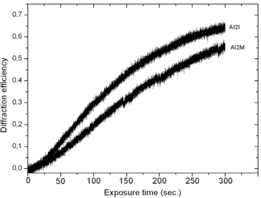
Figure I-19: Typical AFM image of formed SRG on the surface of Azo-polymer film 34 Figure I-20- Diffraction efficiencies of SRG formed on the surface of azo polymer films 35 Figure I-21: Diffraction efficiencies of SRG formed on the surface of azo polymer films 36 Figure I-22: a) 2D and b) 3D view of AFM image of two gratings recorded on the … 37 Figure I-23: Schematic representation of isomerization pressure model. 39
Figure I-24: Schematic representation of model 41
Figure I-25: X1 component of force under a periodical modulation of the incident light 43
Figure I-26: Photoinduced worm-like motion of disperse red 1 azo molecule 44 Figure I-27: Experimental setup used for single beam surface deformation 47 Figure I-28: AFM image of the surface deformation of an epoxy-based azo polymer 48 Figure I-29: AFM image of surface deformation induced by linearly polarized 49
Figure I-30: Photos of optically induced polymer deformation 50
Figure I-31: Up) SEM images of colloidal spheres before irradiation 51
Figure I-32: AFM images of PI surfaces irradiated at the laser fluence of 54
Figure I-33: AFM pictures of LIPSS on the sample film 55
Figure I-34: Schematic representation of input and output coupling by use of SRG 56 Figure I-35: Three fixed angles of incidence on the SRG, produce three 57
Figure I-36: Schematic view of a polarization separator 57
Figure I-37: Schematic of polarization discriminator 58
Figure I-38: Schematic of LC orientation 58
Figure I-39: Experimental setup for the Fourier transform hologram recording 59 Figure I-40: The Fourier transform holograms of a) letter A and b) Letter E recorded 59
Figure I-41: The development of C2v symmetry in the poled SRG 61
Figure I-42: The controlled cell orientation 7 days after inoculation 61
Figure I-43: Substrate patterning process 62
Chapter II
Figure II-1: Anomalies in the first order for a typical grating with triangular grooves 82
Figure II-4: AFM image of the self-organized SRG on the surface 86
Figure II-5: Experimental setup for the measurement self-diffracted 87
Figure II-6: The self-diffracted beam intensity measured as a function of time 88 Figure II-7: First order diffracted beam intensity as a function of time 89 Figure II-8: Intensity of first order diffraction measured as a function of time 90 Figure II-9: Intensity of first order diffraction measured as a function of time 91 Figure II-10: First-order diffraction beam intensity as a function of time for 92
Figure II-11: Evolution of the height and pitch of the grating 93
Figure II-12: Intensity of first-order diffraction beam 94
Figure II-13: AFM images of typical surface grating displaying a SRG 98
Figure II-14: Schematic representation of diffracted beam divergence 99
Figure II-15: Simultaneously writing-readout process of SRG on azo-polymer film 100 Figure II-16: Experimental setup to check the influence of laser beam incidence angle 101 Figure II-17: a) AFM images of SRG for incidence angles of 1)20° and 2) 59° 103
Figure II-18: Relation between pitch and amplitude of gratings 104
Figure II-19: The photo of first and second order backward self-diffraction 105 Figure II-20: a and c are AFM images of the structures formed on the surface 106 Figure II-21: left) AFM images of spontaneous structures formed on the surface 108 Figure II-22: left) 3D AFM image of polymer surface illuminated with a circular 109 Figure II-23: Area histogram of holes created by circularly polarized laser beam 110 Figure II-24: AFM images of surface structures for circular polarization at 110
Figure II-25; Irradiation time dependence of diffracted beam intensity 111
Figure II-26- Scheme of the mechanism of self-structured SRG formation 113
Chapter III
Figure III-1: Experimental scheme for surface relief grating formation 124
Figure III-2: The intensity of the first order diffracted beam as a function of time 126 Figure III-3: AFM images of self-patterned SRG structures obtained after 30 min 127 Figure III-4: Self-patterned SRGs obtained with a totally incoherent beam 129 Figure III-5: Diffracted beam intensity as a function of time for different positions 130 Figure III-6: First order self-diffraction intensity as a function of time 131 Figure III-7: First order self-diffraction intensity as a function of time for the 133 Figure III-8: Intensity of first order self-diffraction as a function of time under 134
Chapter IV
Figure IV-1: Experimental set-up. Beam 1 is at normal incidence on the sample 146
Figure IV-2: Two dimensional Fourier transform of the two SRG spots 148
Figure IV-3: Power spectral density for different distances between the spots 150 Figure IV-4: First order diffraction intensity as a function of time for the coherent 151 Figure IV-5: AFM image and surface profile of self-organized SRG on the surface 155 Figure IV-6: Controlled cell orientation toward the groove direction after one week 157 Figure IV-7: Detail for the direction of growing. The cell begins to grow randomly 157 Figure IV-8: Left: optical microscope image of cells on the self-organized SRG 158 Figure IV-9: Statistics of the cellular orientation relative to the surface submicron 159 Figure IV-10: Coupling of a He-Ne laser at 633 nm inside polymer film 160 Figure IV-11: Schematic representation of light coupling into polymer film 161 Figure IV-12: Diffusion of first order diffracted beam from self-organized SRG 162
Figure IV-13: 2D Fourier transformation of image II-22 163
Figure IV-14: a) AFM image of self-organized structure on the surface 165 Figure IV-15: Experimental setup for measuring optical activity of self-organized 165
List of Tables
Table I-1- Characteristics of monomers 24
Table I-2- Characteristics of the polymers 24
Table I-3- Data for the photoinduced birefringence and kinetic of the relaxation 30 Table IV-1: Implementation of an OR logic gate with pitch Λi as test parameter 152
List of Symbols
A Conserved birefringence B, C Constants d Thickness of film I Light intensity K Wave numberMw Mean molecular weight
m Diffraction order
N Concentration of molecules
P Pressure
r Ratio of molecules which move under coherent beam
Tg Glass transition temperature
α Polarization angle
χ Susceptibility
δ Divergence angle
Δn Birefringence
ε Extinction coefficient
φ Photoisomerization quantum yield
Φ Angle between light polarization and azo dipole axis
ϕ Detection angle of luminescence
λ Wavelength of light Λ Pitch of grating μ Viscosity π Phase difference θ Incidence angle θ’ Diffraction angle
ρ In plane rotation angle
σμ Spatial coherence length
σT,C Absorption cross section of the trans and cis isomers
List of Abbreviations
AFM Atomic Force Microscope
Alq3 Aluminium tris (8-hydroxyquinoline)
CCD Charge-Coupled Device
DC-EFM Dynamic Contact-Electrostatic Force Microscopy
GB Gigabyte
GPC Gel Permeation Chromatography
ITO Indium Tin Oxide
LB Langmuir-Blodgett
LC Liquid Crystal
LCP Left-hand Circular Polarization
LIPSS Laser-Induced Periodic Surface Structures
NF Neutral Filter
NLO NonLinear Optics
p Transverse Magnetic(TM) polarization
RCP Right-hand Circular Polarization
s Transverse Electric (TE) polarization
SBN Strontium Barium Niobate
SEM Scanning Electron Microscope
SHG Second Harmonic Generation
SRG Surface Relief Grating
TB Terabyte
THF TetraHydroFuran
UV UltraViolet
“How far mathematics will suffice to describe,
and physics to explain, the fabric of the body,
no man can foresee.”
d’Arcy Thompson (1860-1948). On Growth and Form. University Press, Cambridge, 2nd edition 1952.
“I find the great thing in this world
is not so much where we are,
but in what direction we are moving.”
Oliver Wendell Holmes (1809-1894)General Introduction
Our environment is a composite of numerous self-organized patterns. An interesting feature of self-organization is the appearance of patterns such as stripes, hexagons, spirals and other complex forms in very different natural or laboratory systems. Patterns on the skin of animals, the nest of social insects, bacterial colonies and so on are examples of self-organized patterns in living objects. However, a look at inorganic nature reveals that formation of pattern is not peculiar to living objects. Pattern formation is the rule also in the non-living world. Formation of galaxies, stars, clouds, rain drops, lightning, river systems, mountains, crystals, all forms of erosion - all testify the generation of ordered structures.
In optics self-organized regular patterns emerge from uniform or randomly structured input optical fields. These patterns can be used in image formation and manipulation techniques to increase the sensitivity or resolution of optical systems, the manufacturing of optical neural networks and associative memories and the use of fractal and wavelet algorithms for image compression.
It is instructive to look for common principles in the generation of all these structures to find a universal explication or model.
Surface relief grating (SRG) formation in azo-polymeric materials is a new form of grating formation in optical materials. SRG is a young branch of research and lot of questions remain unanswered. Migration (diffusion) of azo-molecules from bright region of two coherent beams interference to its dark region result grating formation on the surface of polymer film. This is a density grating and it is stable below glass transition temperature of the polymer. SRG formation is very sensitive to the parameters of optical setup. Several models have been developed to explain SRG formation, but their disadvantages make them inadequate to explain all of experimental results.
Spontaneous hexagonal pattern formation has been reported on the surface of azo-polymer thin films when exposed with a single coherent laser beam. The subject of our study concerns the self-organization of molecules to form a regular pattern in a homogeneous azo-polymer film.
In this thesis we present a simple experimental method based on diffusion of azo-molecules irradiated with a uniform single laser beam. Patterns are sensitive to the polarization of laser beam and polarization multiplexing of more than two states could be achieved. As it will be
explained in this dissertation in a later chapter, it is possible to self-organize azo-molecules by illuminating them with a large incoherent laser beam accompanied with a small low power coherent laser beam. Self-organization starts from coherent beam region and propagates step by step and finally covers the whole incoherent beam region because of cooperative self-organization of azo-molecules. The last part of the study deals with the applications of this new method of self-organization. We proposed cooperative self-organization of individual azo-molecules as optical processors and logic gate for neural networks. In this study, self-organized SRG patterns are used for controlling neuron growth direction, waveguide coupler, optical diffuser and 2D chiral structure.
Overview of the thesis
The first chapter is devoted to the presentation of self-organization and a general review of azo-polymer film deformation. A brief summary of self-organization in nature and optics will be given. The idea of surface relief grating formation, proposed models and its possible applications will be developed in this chapter. We will discuss single laser beam deformation of polymer films in greater details because our study is based on self-organization of azo-polymers. In this chapter we will also present our polymeric materials and experimental results about light induced birefringence and two beam SRG formation.
In the second chapter we present our experimental results of spontaneous ripple pattern formation in the azo-polymers in question. We study the effects of material structure, optical setup (power, polarization and incident angle of laser beam), reversibility and relaxation of pattern. We also present polarization multiplexing of more than two polarization states for digital optical data storage using spontaneous ripple patterns.
The third chapter will be devoted to describe incoherent light induce self-organization in azo-polymers. We will give more details on the mechanism of cooperative self-organization of azo-molecules.
In the last chapter we present some applications of self-organized patterns. We will present our experimental results of nonlocal communication of azo-molecules. We also discuss the possibility of creation of neural networks with these systems. The experimental results of
In the appendixes, the relation between coherency of light and visibility of interference pattern, and a simple model of azo-molecule photo-isomerization are discussed in great details.
Chapter I
Self-organization and
surface relief gratings
I-1- Introduction
The scientific study of self-organizing systems is relatively new, although questions about how organization arises have of course been raised since ancient times. Many natural systems show organization (e.g. galaxies, planets, chemical compounds, cells, organisms and societies). There has been a tremendous increase in the study of self-organization in optical systems. This chapter is devoted to review of some natural self-organized systems, optical patterns and surface relief grating (SRG) formation as a basic for self-organized SRG formation in azo-polymers. We first will give introduction on the self organization in nature as well as in optics. We will present a discussion on SRG formation in azo-polymers including proposed mechanisms and some applications. We will also discuss one beam deformation of azo-materials. A new series of azo-polymers will be introduced. The results of light induced birefringence and SRG formation will be presented.
I-2- Self organization in nature
Pattern formation is a truly interdisciplinary science. The similarity in fundamental mechanisms and the accompanying mathematics brings together scientists from many disciplines, such as biology, chemistry, fluid dynamics, material science, mathematics, medicine, geophysics, ecology, physics and surface science. Natural patterns turn up all over. They show up as ripples in the sand washed by the tide or the undulating ripples of a desert dune. One sees them on the tips of one’s fingers as fingerprints, as well as in the stripes of a tiger or zebra and the spots of a leopard. Honeycomb is another example of self-organization in nature (Figure I-1).
a
b
c
d
Figure I-1: Some self-organized patterns in nature. a) Hexagonal structure of honeycomb, b) Ripple pattern on the sand-flats left at low-tide c) Pattern on a butterfly's wing c) Ripples pattern of a desert dune
The honeycomb cells repeat their hexagonal symmetry to cover whole surface of a honeycomb. The honeybee is naturally able to measure dimension of honeycomb cells. Thousands of individual honeybees work cooperatively to build a regular honeycomb structure. But a beehive is not only a simple array of hexagonal cells, each comb has three separate regions: a central part for brood, a ring of cells around central part that filled with pollen and finally a large marginal region of cells for storing of honey [1, 2].
Another natural architect is the nautilus. The shell of nautilus has a logarithmic spiral shape. This precise curve develops naturally as the shell increases in size but does not change its shape. The process of self-similar growth yields a logarithmic spiral. We can find the same spiral in the horns of mountain sheep and in the path traced by a moth drawn towards a light. The nests of social insects like ants and termites are another example of self-organization in nature. Different kind of delicate and highly regular structures have been built by numerous groups of ants and termites. For example, the nest of Apicotermes termites comprise a lot of heaped horizontal chambers connected by helix-shaped vertical passages that are used as spiral staircases [3]. From outside the nest includes a series of regularly spaced pores that open towards corridors circulating inside the internal wall of the nest.
Traditional scientific fields attempt to explain these features by referencing the micro properties or laws applicable to their component parts; for example they assumed that seashells (decorated with bold patterns of stripes and dots) were precisely specified in the genetic blueprint contained in the mollusk’s DNA. But some years ago, scientists, skilled in both biology and computer science, began to look at pattern formation in an exciting new way. One of the first things they realized was that two individuals of the same species were similar, but not identical. Like the fingerprints on one's hand, they are alike yet not alike. This simple observation led them to hypothesize that the patterns on shells, the stripes on a zebra, and the ridges on our fingertips are not rigidly predetermined by the genetic information inside the cell's nucleus. Organisms are not built as a house is built, by meticulously following an architect's plans. Instead, genes appear to take a more generalized approach, specifying sets of basic rules whose implementation results in organized form and pattern.
In the day life we can see several type of self-organization like cubic structure of salt crystals and six-sided stars or hexagonal needles shape of snowflakes.
All of natural patterns are not regular; we can find some irregular patterns like billowy clouds, flickering flames, lightning bolts, the pattern of veins on a leaf and the architecture of the lung's passageways. Such objects have been called fractals and they are not simply random system. They often display an underlying structure, a kind of regular irregularity.
One of the greatest biological mysteries yet to be solved is how a single egg, apparently without structure, becomes a child. The human cell does not contain enough information to specify the location and connections of every neuron in the brain. Therefore, much of the body's organization must arise by means of more simple developmental rules. In nature many systems display extreme complexity, although their fundamental components may be rather simple. The brain is an organ of high complexity, but an isolated neuron cannot think. Complexity results from interactions between large numbers of simpler components. Simple interactions between a large numbers of subunits or components of a system could yield intricate and beautiful patterns.
The study of complexity provides new insights into how patterns develop in nature. One exciting finding is that order often arises spontaneously from disorder; patterns can emerge through a process of self-organization.
Self-organized systems are structure formations without any clear association from outside of the system. Any system that takes a form that is not imposed from outside (by walls, machines or forces) can be said to self-organize. In other words, a self-organization results from the interactions among the components of the system and is an internal phenomenon. The organization can develop in either time or space, maintain a stable form or show transient phenomena. The size of self-organized patterns typically is much larger than the size of individual components and in some natural patterns their ratio can reach 104-105. General resource flows within self-organized systems are expected (dissipation), although not critical to the concept itself. For example in spite of conflicting actions between insects, collective structures which fulfil numerous functional and adaptive requirements are produced [4]. Noise (fluctuations) can allow metastable systems to escape one basin and to enter another, thus over time the system can approach an optimum organization or may swap between the various patterns, depending upon the size and nature of the perturbations. For instance, individual insects are not able to process a large quantity of information but simply their response to stimulus from other individuals or environment (these stimulus don’t carry any
signs, simply they are attractive or repulsive, activating or inhibiting) lead to pattern formation. The individual units just have access to local information [5, 6].
The field of self-organization seeks general rules about the growth and evolution of systemic structure, the forms it might take, and finally methods that predict the future organization that will result from changes made to the underlying components (past construction sets the stage for new building actions)[7].
With simple computer programs that simulate a natural process we can visualize most of simple self-organized patterns in nature. Cellular automata are one of the well known categories of computer programs in this field. They are simulations played on the equivalent of a computer checkerboard. In the simplest version, one starts with a single row of cells. Concerning seashells, each square of the checkerboard represents a hypothetical cell along the edge of the snail's mantle. The cell could either produce a colour pigment or none at all. By developing the system, the state of cell (whether it produces pigment or not) is determined by the initial state of cell and the state of its nearest neighbour cells on either side. We can assume a rule for pigment production; if the cell and one of its nearest neighbours currently produce pigment, then the cell will continue to produce pigment in the future. The state of the cells changes over time and each row of the checkerboard displays the next step in the process, just as the growing shell displays its developmental history. It is interesting to know that even if one starts out with a completely random array of cells at the beginning, a remarkably organized pattern emerges (order arises from disorder). More complicated cellular automata models have been developed to explain the stripes on zebras, the mottled patterns on fish, the growth of snowflakes, and even clustering of neurons in the brain.
Nevertheless, studying nature requires timescales appropriate for the natural system, and this restricts our studies to identifiable qualities that are easily reproduced, precluding investigations involving the full range of possibilities that may be encountered. However, mathematics deals easily with generalised and abstract systems and produces theorems applicable to all possible members of a class of systems. By creating mathematical models, and running computer simulations, we are able to quickly explore large numbers of possible starting positions and to analyse the common features that result. Even small systems have almost infinite initial options, so even with the fastest computer currently available, we usually can only sample the possibility space. Yet this is often enough for us to discover
interesting properties that can then be tested against real systems, thus generating new theories applicable to complex systems and their spontaneous organization.
I-3- Pattern formation in optics
Several researches have been developed on the study of the structure formation in optical systems because optics has several advantages such as flexibility and the simplicity of handling. The interaction of an intense laser beam with a nonlinear medium (a medium in which the optical properties depend on the intensity of the incident light) can lead to spontaneous patterning. The interplay of spatial coupling by diffraction and nonlinearity is responsible for the pattern formation. There are various configurations in which optical pattern formation is studied. Arecchi et al. reviewed pattern formation in NLO (Nonlinear Optics) materials in reference 8.
Single mirror feedback is one of the common optical setup to demonstrate optical pattern formation (Figure I-2). The system is a thin nonlinear medium irradiated from one side by a spatially smooth collimated beam with a feedback mirror a distance d away to generate a counterpropagating beam in nonlinear medium. Usually diffusion length of materials is much larger than light wavelength and we can neglect gratings with small pitch arising from interference of forward and backward beams. These counterpropagating beams interact in media to create spatial instabilities that lead to regular pattern formation.
d
Figure I-2: Single-mirror feedback experiment
Several types of patterns like; stripes, squares, triangles, hexagons and more exotic quasiperiodic or superlattice planforms in different types of NLO materials including atomic vapours, liquid crystals, and photorefractive crystals have been produced [9-18]. Recently
pattern forming optical system. A heated cell (length L = 15mm) containing sodium vapour in a buffer gas atmosphere has been irradiated by a laser beam. The cell temperature was about 340°C (sodium particle density was approximately 1014 cm−3) [19]. By increasing the ellipticity of the laser beam polarization from zero they obtained a transition from squares (Figure I-3-a) to positive hexagons (Figure I-3-b) followed by stripes (Figure I-3-c) and finally by negative hexagons in sodium vapour (Figure I-3-d).
Figure I-3: Transition sequence from squares to positive hexagons, to stripes and finally to negative hexagons for increasing positive ellipticity. a)–d) Total near field intensity distribution of the backward laser beam. e)–h) Optical Fourier transform of the transmitted laser beam [19].
Bennink et al. reported feedback free hexagonal pattern formation by simple passage of a single laser beam through sodium vapour cell [20]. Because of nonlinear optical self-action effects, when a laser beam propagates through sodium vapour, it breaks up into three components. Honeycomb pattern formation in far-field is the result of coherent superposition of the diffraction pattern from each of the three beams (figure I-4).
Figure I-4: Example of pattern formation as observed in the near field (left) and far field (right). Typical conditions were input power, 150 mW; input beam diameter, 160 mm; laser frequency, 2 GHz blue-detuned from the sodium D2 line; cell length, 7 cm; and number density, 8 x1012 cm-3 [27].
They have presented deviation of patterns by varying laser power and laser frequency. In the particular case of a 47 mW laser power, they observed strip patterns in far-field. The laser powers for this pattern formation are above the self-trapping power of system.
The coherence of optical beams is necessary for interference effects and consequently is an important parameter in optical pattern formation. But several studies of pattern formation with partially spatially incoherent light, created from a coherent laser beam, have shown that coherent light is not mandatory for pattern formation, only there is an instability threshold for such systems in comparison with coherent light [21-27].This threshold can be related to the balance point between constructive (nonlinear self-focusing) and destructive (linear diffusion) effects and depends on the correlation statistics [28]. The pattern formation with incoherent light is possible when the response time of the nonlinearity of system is much longer than the characteristic time of light random phase fluctuations so speckle structure doesn’t perturbed pattern formation.
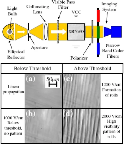
Schwartz et al. presented spontaneous pattern formation in (Strontium Barium Niobate) SBN: 60 photorefractive crystal with an incoherent white light originating from an ordinary incandescent light bulb [29]. Figure I-5 shows experimental setup and the light intensity distribution at the crystal output. Spatial correlation distance and temporal coherence length of light source were ~8 mm and 0.5 mm respectively. Nonlinearity was controlled by an
of unpolarized input light (parallel to the c axis) propagates in a nonlinear fashion and serves as a signal beam .The ordinary polarized beam serves as background beam. A CCD camera is used to monitor the intensity distribution of extraordinary beam. Below threshold they did not observe pattern. Above threshold a stripe pattern with period of 40 μm is formed and by future increasing applied electric field, pattern becomes dipper.
Figure I-5: up) Experimental setup; down) Total intensity distribution at the output face of the crystal: homogeneous intensity at linear propagation (a) and stable nonlinear propagation below the modulational instability threshold (b); pattern formation above threshold (c), (d) [29].
The experimental results showed that for all temporal frequencies, threshold value and periodicity of pattern are the same which confirm that pattern formation in this system is a collective phenomenon.
For the first time Hubert et al. showed that, under certain experimental conditions, it is possible to observe a two dimensional hexagonal structures on the surface of an azo-polymer
with a single continuous wave laser beam [30, 31]. It is important to note that this process of structuring is different from that leading to the formation of SRGs: here only one beam is necessary against two for the formation of SRGs. Moreover, in the case of SRG formation, the azo molecules suffer a bright and dark zones corresponding to interferences pattern of two writing coherent beams and they follow this pattern with a phase difference of π to create SRG. In the case of spontaneous patterning, on the scale of the molecule, there are no intensity or polarization gradient. In whole of irradiated surface, it does not have a priori dark zones where the molecules are not excited and all the molecules are continuously subjected to the laser light. Figure I-6 shows the setup used for this experiment.
Figure I-6: Experimental setup for spontaneous patterning on azo polymer surface. Scheme taken from Ph D thesis of Christophe Hubert (CEA-R-6038, September 2003).
A typical atomic force microscope (AFM) image of the self-organized structure on the surface of an azo-polymer is presented in the figure I-7. The laser irradiation induced regularly spaced structures with the form of circles. If six circles are considered, it is possible to define a hexagon whose principal axis is directed according to the direction of polarization of the light. In the image, this hexagon is schematized in white. The obtained structures are not perfectly regular.
Figure I-7: Typical AFM image of self-organized structure on the surface of an azo-polymer film. The thickness of film is 220 nm. The structure inscribed by a p polarized Ar+ laser (514 nm, 300 mW/cm2) for 100 minutes [Ph D thesis of Christophe Hubert (CEA-R-6038, September 2003)].
The period of these structures were in the order of laser light wavelength and the amplitudes were several hundreds of nanometre. The direction of orientation of the structures follows the direction of laser beam polarization. And for circular polarization there is no defined direction for the orientation of induced structure. For the same experimental conditions, the polarization direction doesn’t affect the modulation amplitude of the structure. The modulation amplitude was sensitive to the incidence angle and strongly decreases as the incidence angle exceeds 5° for both s and p polarization [32]. The growth rates of induced structures were increased linearly by the intensity of irradiation. Also the results showed that these structures are not totally reversible not only optically but also by increasing the temperature of samples over Tg of polymer film.
As a direct application of such structures, Hubert et al. have studied the effect of two dimensional (2D) microstructuring on the photoluminescence properties of an Organic Light-Emitting Diode [33]. Figure I-8 shows the fabricated device structure. The results showed that the amount of photo-luminescent light extracted from the patterned part of the device was 3.4 times larger than extracted from the nonpatterned part. Extracted light intensity significantly depends on the observation angle.
Figure I-8- The structure of the light-emitting device: a rubrene-doped Alq3 light-emitting
layer is evaporated onto the aluminum-coated DR1MA/MMA structured polymer film. The out-coupled light from the device resulting from photo-excitation of the luminescent layer with ultraviolet UV light (λexc=350 nm) is collected by an optical fiber set at an angle ϕ from
normal incidence and analyzed by a spectrometer. Only one part of the polymer surface is patterned for comparison with a nonpatterned structure. The sample can be rotated around different axes: out of plane (angleθ) or in plane (angle ρ). Thicknesses of the DR1MA/MMA, aluminum and Alq3 layers were, respectively, equal to 500, 100, and 100 nm [33].
I-4- Photochemistry of azobenzene
Azobenzene is a chemical compound composed of two phenyl rings linked by an N=N double bond. The term azobenzene or simply azo is often used to refer to a wide class of molecules that share the core azobenzene structure, with different chemical functional groups extending from the phenyl rings (technically, these compounds should be referred to as diazenes). The azobenzene compounds strongly absorb light, and were historically used as dyes in a variety of industries. One of the most intriguing properties of azos is photo-isomerization behavior between two isomers, the trans and cis configurations [34]. The two isomers can be switched with particular wavelengths of light: ultraviolet or blue light, which corresponds to the energy gap of the π-π* (S2 state) transition, for trans-to-cis conversion, and blue light, which is
equivalent to that of the n-π* (S1 state) transition, for cis-to-trans isomerization. For a variety
of reasons, the cis- isomer is less stable than the trans (for instance, it has a distorted configuration and breaks the aromaticity of the trans configuration). Thus, cis-azobenzene
will thermally relax back to the trans via cis-to-trans isomerization. The trans isomer is more stable by approximately 50 kJ/mol, and the barrier to photo-isomerization is on the order of 200 kJ/mol [35-37]. a) hν hν’, KT Trans Cis b) εcis φtrans
200 kJ/mol εtrans φcis
~50 kJ/mol k
Figure I-9: Azobenzene can be converted from the trans to the cis state photochemically, and will revert back to the stable trans state thermally. Alternately, the cis to trans conversion can be effectuated with a distinct wavelength of light. (b) Simplified state model for azobenzene chromophores. The exinction coefficients are denoted ε, whereas the quantum yields for the photoisomerizations are labelled φ. The rate of thermal relaxation is denoted by k.
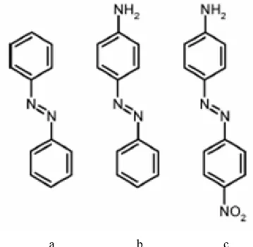
The exact wavelength at which azobenzene isomerization occurs depends on the particular structure of each azo molecule, but they are typically grouped into three classes [34]: the azobenzene-type molecules, the amino-azobenzenes, and the pseudo-stilbenes (Figure I-10).
a b c
Figure I-10: Examples of azobenzene molecules that fall into the three spectroscopic classes: (a) azobenzenes (b) aminoazobenzenes, and (c) pseudo-stilbenes.
These azos are yellow, orange, and red, respectively, owing to the subtle differences in their electronic absorption spectra. The compounds similar to the unsubstituted azobenzene exhibit a low-intensity n-π* absorption in the visible region, and a much higher intensity π-π* absorption in the ultraviolet. Ortho- or para-substituted azo dyes with electron-donating groups (such as aminos), are classified as amino-azobenzenes, and tend to closely spaced n-π* and π-π* bands in the visible. The pseudo-stilbene class is characterized by substituting the 4 and 4' positions of the two azo rings with electron-donating and electron-withdrawing groups (that is, the two opposite ends of the aromatic system are functionalized). This push-pull configuration results in a strongly asymmetric electron distribution, which modifies a host of optical properties. In particular, it shifts the absorption spectra of the trans- and the cis- isomers, so that they effectively overlap. Thus, for these compounds a single wavelength of light in the visible region will induce both the forward and reverse isomerization. Under illumination, these molecules will be constantly cycling between the two isomeric states. This, in part, explains why the pseudo-stilbenes give rise to the most efficient photo-response, especially in cases where motion of the azo chromophore is required. In cases where the azo isomerization is being used as a switch, or where a two-state system is desired, this overlap of the spectra is obviously undesirable. The photo-isomerization of azobenzene is extremely rapid, occurring on picosecond timescales [38, 39]. The thermal back-relaxation varies greatly
aminoazobenzenes, and seconds for the pseudo-stilbenes. The energy barrier for this thermal isomerization is on the order of 90 kJ/mol [40, 41]. Even in the case of the parent azobenzene, the cis lifetime is not long enough for the molecule to be treated as a stable two state system. Considerable research has gone into elongating the cis lifetime, which would then allow the two states to be selected without unwanted interconversion (useful in applications that require two stable states, such as data storage). Typically, bulky substituents have been used to hinder the thermal back reaction. For instance, a polyurethane with the azo chromophore in the main-chain exhibited a lifetime of 4 days (thermal rate-constant of k = 2.8×10⁻⁶ s−1, at 3◦C) [42], and an azo substituted with bulky pendants had a lifetime of 60days (k < 2×10⁻⁷ s−1, at room temperature) [43]. The inherent conformational strain of macrocyclic azobenzene compounds has been used to create a much more stable cis populations, with lifetimes of 20 days (k = 5.9×10⁻⁷ s−1) [44], 1 year (half-life 400 days, k =2×10⁻⁸ s−1) [45, 46], or even a lifetime of 6 years (k = 4.9×10⁻⁹ s−1) [47]. Similarly, using the hydrogen-bonding of peptide segments, a cis lifetime of <40 days (k = 2.9×10⁻⁷ s−1) was achieved [48]. In extreme cases, the cis species
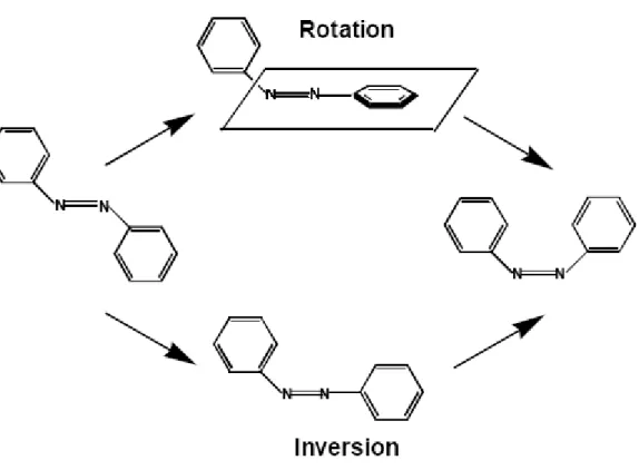
can be stabilized by completely preventing isomerization: by attachment to a surface [49], synthesis of ring-like molecules [50], or even, in the case of the parent azobenzene, crystallization of the cis form [51,52]. These experiments again emphasize that the azo isomerization requires a large geometric change in molecular configuration. The thermal back-relaxation is generally first-order, although the distribution of highly constrained configurations that arise in a glassy polymer matrix can lead to anomalously fast decay components [53-56]. Accordingly, higher matrix crystallinity increases the decay rate [57]. The mechanism of isomerization has been the subject of some debate, with two pathways identified as viable: a rotation about the N=N bond, with disruption of the double bond, or via an inversion, with a semi-linear and hybridized transition state (Figure I-11). It has been suggested that the trans-to-cis conversion occurs via rotation into the S2 state, whereas
inversion gives rise to the cis-to-trans conversion. It is still under discussion which excited state plays a direct role in the series of the photoisomerization behavior. However, the latest research on femtosecond transition spectroscopy has suggested that the S2 state undergoes
internal conversion to the S1 state, and then the trans-to-cis isomerization proceeds. The
conversion from trans to cis reduces the distance between the ends of the moiety (between the 4 and 4’ positions): from 0.99 nm in the trans state to 0.55 nm in the cis state [58-60]. This change in geometry results in a change in the molecular dipole, increasing it from essentially zero in the trans state to 3.1 D in the cis form (for the parent azobenzene) [51] . The free
volume requirement of the cis is larger than the trans [61], with estimates of approximately 0.12 nm3 required for isomerization to proceed via an inversion of the azo bond [55, 62], and 0.28 nm3 for a rotation about the azo bond [42]. This large molecular change generates a nanoscale force, which has been successfully measured in single-molecular force spectroscopy experiments [63, 64].
Figure I-11: Rotation and inversion mechanisms pathways for azobenzene isomerization process.
Azobenzene units are extremely sensitive to packing and aggregation, with π–π stacking causing shifts in the absorption spectra, and changes in photophysical properties. When the azos are aligned in a parallel fashion (head-to-head), they are called J-aggregates, and give rise to a red-shift compared to the well-isolated chromophore spectrum. If the dipoles are instead antiparallel (head-to-tail), they are called H-aggregates, and one observes a blue-shift. The local packing can be influenced, of course, by solvent conditions and molecular architecture. For instance, local water concentration in tetrahydrofuran (THF) solutions can markedly change the azo isomerization behaviour [65]. In fact, even a small water fraction (a few percent) was found to be sufficient to give rise to measurable differences [66]. In these cases, as water content increases, the azo units are driven to aggregate. This aggregated
I-5- Photo-induced orientation
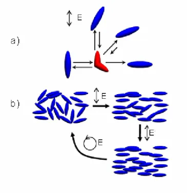
The photo-isomerization of azobenzene is a unique form of light-induced molecular motion. This motion can also lead to motion on larger length scales. For instance, polarized light will cause the molecules to isomerize and relax in random positions. However, those relaxed (trans) molecules that fall perpendicular to the incoming light polarization will no longer be able to absorb, and will remain fixed (the probability of photon absorption varies as cos2Φ, where Φ is the angle between the light polarization and the azo dipole axis. ). Thus, there is a statistical enrichment of chromophores perpendicular to polarized light (orientational hole burning) (Figure I-12). The photo-orientation is reversible: isotropy can be restored using circularly polarized light, or a new orientation direction can be selected by irradiation with a new polarization.
Figure I-12: The mechanism of statistical photo-orientation of azo molecules. (a) The molecules aligned along the polarization direction of the incident light will isomerize, and take on a new random orientation. The molecules that lie perpendicular to the polarization of light cannot absorb a photon and remain fixed. (b) An initially isotropic distribution of chromophores will become progressively aligned with polarized irradiation. Irradiation with circularly polarized light can restore isotropy [K. G. Yager, C. J. Barrett, Journal of Photochemistry and Photobiology A: Chemistry, 2006, 182, 250–261].
Polarized irradiation will make an azo-material anisotropic and therefore optically birefringent and dicroic [67, 68]. In these systems, the physical and optical properties such as
the absorption spectrum, dipole moment, refractive index, and molecular conformation can be reversibly changed through the trans-cis isomerization of azobenzene. This photo-orientation can also be used to orient other materials (especially in liquid crystal systems). For instance, it has been used to selectively orient liquid crystal domains, and to create NLO materials and high density data storage [69-74]. Azo isomerization can also be used as switching elements for microelectronics and to photo-switch the liquid crystal phase of a material [75-79]
The azobenzene moiety is robust and adaptable, having been incorporated into a wide variety of different system types, including: small molecules, doped into polymeric systems, supramolecular assemblies, liquid crystals, and covalently bonded to crystalline or amorphous polymers. Although doping is an easy and convenient way to include azobenzene in a matrix of choice, it is usually found that mobility leads to aggregation and crystallization of the azo molecules, making the resultant films heterogeneous and optically cloudy. Thus, by far the most often-employed incorporation strategy is to covalently bind the azo chromophore to a polymer backbone [80].
In 1995, it was discovered that exposing a thin film of azo-polymer to a light intensity (or polarization) gradient leads to spontaneous surface patterns [81, 82]. In essence, the polymer material will reversibly deform so as to minimize the amount of material exposed to the light. This phenomenon is not laser ablation, since it readily occurs at low power and the transformation is reversible. The exact mechanism of this surface holography is still unresolved, although it is clearly related to the azobenzene isomerization.
I-6- A new series of azo-polymers
In this work we present a series of new azo copolymers for light induced phenomena. The chromophoric monomers were derivatives of azobenzene containing heterocyclic sulfonamide moieties. The monomers of the methylacrylate type contained aliphatic spacers of different length between chromophoric and methylacrylic groups. These monomers were polymerized in order to obtain homopolymers and copolymerized with butyl methylacrylate (MB) and 2-ethylhexyl acrylate (AI) to get copolymers containing various percentages of chromophoric units [83].
a b
Figure I-13: Chemical structures of copolymers: a) MBYI and b) AI2I&M copolymer series.
I-6-1-Characteristics of the monomers and polymers [83]
The purity of monomers and polymers was determined by thin layer chromatography using Merk Silicagel aluminium foils.
Melting temperatures (M.p.), maximum absorbance wavelength (λmax) and dipole moments
(μ ) of side chain units are presented in table I-1. Symbols follow SMILES notation. Melting temperatures of the monomers containing sulfisomidine heterocyclic ring (2, 6-dimethylpyrimidin-4-yl) of the YI(IZO-n) series are higher than sulfamethoxazole monomer 2M(MET-2). Dipole moments have been calculated by Gaussian RHF/3-21g for isolated molecule. The dipole moment of trans isomer of 2I is grater than 3I and 1I and that of 2M is smaller than all of others.
Table I-1- Characteristics of monomers Monomer Μ.p (K) λmax (nm) μ / 10−30 (C m) trans cis 1I(IZO-1) 457.5-461 440 34.10 27.84 2I(IZO-2) 448-451 446 35.29 17.53 3I(IZO-3) 401-403 450 34.65 13.28 2M(MET-2) 395-397 454 29.31 14.14 IZO-1:2-[{4-[(E)-(4-{[(2,6-dimethylpyrimidin-4-yl)amino]sulfonyl}phenyl)diazenyl]phenyl}
-(methyl)amino] ethyl 2-methylacrylate. IZO-2 : 3-[{4-[(E)-(4-{[(2,6-dimethylpyrimidin-4-yl)amino]sulfonyl}phenyl) diazenyl] phenyl}-(methyl)amino] propyl 2-methylacrylate.
IZO-3 : 2-{2-[{4-[(E)-(4-{[(2,6-dimethylpyrimidin-4-yl) amino]sulfonyl}phenyl)diazenyl]
phenyl}-(methyl)amino] ethoxy } ethyl 2-methylacrylate. MET-2 : 3-(methyl{4-[(E)-(4-{[(5-isoxazol-3-yl)amino]sulfonyl}phenyl)diazenyl]phenyl}-amino) propyl 2-methylacrylate. Mean molecular weight,M , of polymers has been determined by GPC using Waters 917 W
columns, RIDK-102 detector and APEX ver. 3.1 recorder. A mobile phase was γ-butyrolactone and molecular weight referes to polystyrene standards.
A Mettler Toledo DSC has been used for glass transition temperature (Tg) determination of polymers with scanning of 20K/min.
Table I-2 shows glass transition temperature, wavelength of maximum absorbance and absorbance at the working wavelength of the polymers. MB1I has highest and AI2M the lowest Tg. The maximum absorption wavelengths are around 435 nm and MB3I has highest absorption for the concentration of 50 mg/ml of polymers in the solution.
Table I-2- Characteristics of the polymers Polymer n M M W Tg (°C) λmax (nm) A488 MB1I(IZO-1/20 MB) 12600 15900 86.2 433 1.3 MB2I(IZO-2/20 MB) 10750 15800 71.1 438 1.33 MB3I(IZO-3/20 MB) 11750 16500 71.5 435 1.55 AI2I(IZO-2/20 MB) 11450 16250 57.5 435 1.13 AI2M(MET-2/20 AI) 53 445 1.42
MB- butyl 2-methylacrylate, AI- 2-ethylhexyl acrylate
I-6-2-Absorption spectrum
The thin films were made by spin coating of THF solutions of the polymers on the glass substrate. The concentration of polymer in the solution was 50-70 mg/ml. After spin coating,
remained solvents. The thicknesses of the polymeric thin films were measured by Dektak-6M Stylus Profiler and were in the range of 0.5-1 μm for different concentrations and speed of coating. The UV-visible spectra were made using lamda19 spectrophotometer. Figure I-14 shows the spectrum of the polymer films.
300 400 500 600 700 800 900 0,0 0,5 1,0 1,5 2,0 2,5 Absorban ce Wavelength (nm) MB1I MB2I MB3I AI2I AI2M
Figure I-14: Absorption spectrum of azo-polymer films
It is obvious from figure I-14 and the data of table I-2 that absorption spectra (bonds) lies in the blue-green region of spectrum and for wavelengths bigger than 600 nm the films are transparent. For this reason we can use blue-green lasers, such as Ar+ or diode lasers, as writing beam to create light-induced birefringence, two beams surface relief gratings and self-organized structures and red He-Ne laser as probe.
I-7- Light induced birefringence
The first report on photoinduced anisotropy in azo polymer was about the change of its physical property, dichroism, under illumination with polarized light [84]. Photoinduced dichroism was explained by the reorientations of the photon-absorbing molecules to a preferred direction [85, 86]. Later, it was known that this photoinduced rotation of molecules was associated with the photoinduced isomerization of azobenzene [87, 88]. Since the photoinduced dichroism and birefringence of azobenzene were applied to optical holography [89-92], azobenzene containing polymers have been widely studied in the past decade because of their capability of application for reversible optical data storage.
The mechanisms of inducing the birefringence by linearly polarized light can be simply understood. First of all, azo dye molecules in the coated layer in the film are initially in the more stable trans state, and the direction of the long axis of each molecule is random. When a linearly polarized light is illuminating the film, the trans molecule absorbs the light and transfers to an excited state. After the lifetime of the excited state, the excited molecule returns to the initial trans-state or cis-state. The molecule in one of the two states can absorb the light again. The absorption of the cis-state molecule does not depend on the polarization state of light, but absorption of the trans molecule is proportional to cos2Φ, where Φ is the angle between the polarization and the long axis of the molecule. This is called angular selective absorption, and it leads to angular hole burning. As the azobenzene molecules undergo this cycle more and more, trans molecules are gradually oriented perpendicular to the polarization direction of incident light. Because of anisotropy of trans molecules, birefringence is induced Figure I-15.
Figure I-15- Schematic illustration for the mechanism of photo-chemically induced birefringence in an amorphous azo-polymer [M. Hasegawa, T. Ikawa, M. Tsuchimori, O. Watanabe, Journal of Applied Polymer Science, 2002, 86, 17–22].
The experimental setup for measuring light-induced birefringence is shown in figure I-16. An Ar+ laser (488 nm) is used as pump beam inside the absorption band of polymers, and a He-Ne laser (633 nm) is used as a probe beam. A laser beam at 632.8 nm did not affect the film, because its wavelength is far enough from the absorption band of materials not to be absorbed by the polymer.
The transmission of the He-Ne laser through the film placed between crossed polarizers is recorded by a photodiode as a function of time after irradiation with the pump beam polarization set at 45° angle with respect to the probe beam polarization. The intensity of the incident probing beam was reduced to a few percent of the pumping beam intensity. This intensity was enough to ensure that the probe beam did not affect the molecular orientation.
Polarizer Analyzer Polymer film Detector Polarizer Probe beam He-Ne laser Pump beam Ar+ laser Analyzer Pump beam polarization α = 45°
Figure I-16: Experimental setup for measurements of the light-induced birefringence. The polarization direction of pump beam set to 45° with respect to polarizer and analyzer direction of probe beam.
The pump induces optical anisotropy in the film via trans-cis-trans photoisomerization and reorientation of azo dyes. Birefringence modulus Δn is given by equation (1):
⎟⎟
⎠
⎞
⎜⎜
⎝
⎛
=
Δ
o oI
t
I
d
n
arcsin
(
)
π
λ
, (1)where λ0, d, I (t) and I0 are wavelength of the probe beam, thickness of the film, intensity of
transmitted and incident probe beam, respectively.
Figure I-17 shows a typical birefringence excitation - relaxation sequence. The pump beam is turned on at point A, the stable trans isomer of azo unit absorb the pump light and undergo a trans-cis photo-isomerization and then cis isomer relax thermally or by absorbing the pump light to trans isomer that finally is perpendicular to pump beam polarization, create an anisotropy in the film and the birefringence signal increases rapidly and reaches saturation. The writing beam is then turned off at point B; because of thermal relaxation, the orientation
constant value that will be kept constant for a long time in the dark. This birefringence can be erased by illuminating the sample by a circularly polarized pump beam or by increasing the temperature over Tg of polymer.
0,0000 0,0005 0,0010 0,0015 0,0020 0,0025 0,0030 0,0035 0,0040 0,0045 0,0050 0,0055 B A 100 90 80 70 60 50 40 30 20 10 0 Δ n Time (s) AI2M MB1I MB2I MB3I AI2I
Figure I-17: Birefringence Δn in polymer films as a function of time: (A) The pump (writing) beam is turned on. (B) The writing beam is turned off. Pump beam intensity is 100 mW/cm2.
The birefringence is measured by a He-Ne laser at 632.8 nm.
The dynamics of birefringence decay, in the absence of pump beam, have been studied by biexponential function for the assumption of fast and slow decays [93].
The biexponential function is
)
exp(
)
exp(
)
(
t
A
B
1t
C
2t
n
=
+
−
α
+
−
α
Δ
(2)where A is the birefringence conserved for a long times, α1, α2 are the decay constants with
amplitudes of B and C respectively. The fast process (α1) is mainly attributed to the
movement of local polymer segments [94]. The normalized parameters obtained by fitting equation 2 to the experimental results summarized in table I-3. K is cis-trans thermal relaxation rate [95].The results show that for low-Tg azo-polymers, saturated value of Δns and
stable values of the photoinduced birefringence A decrease with the decrease of Tg. The relaxation rates, α1 and α2, of the photoinduced birefringence increase with the decrease of
Tg. As the Tg decreases, the mobility of azo chromophores is higher and thermal back relaxation of photo-oriented chromophores is more favourable [96].
Table I-3- Data for the photoinduced birefringence and kinetic of the relaxation.
Polymer A Β C α1 (1/s) α2 (1/s) Κ(1/s) Δns MB1I 0.66 0.279 0.275 0.446 0.053 - 0.0051 MB2I 0.67 0.307 0.3099 0.476 0.068 0.0944 0.0052 MB3I 0.63 0.374 0.268 0.431 0.032 - 0.0048 AI2I 0.68 0.354 0.276 0.63 0.045 - 0.0045 AI2M 0.6 0.33 0.319 0.9 0.058 0.1617 0.0038
The process is interpreted as trans-cis-trans isomerization and reorientation of the azobenzene derivatives. Many write-erase cycles can be achieved without significant degradation. These results show that the polymer films in question can be used for reversible optical data storage purposes.


![Figure I-24: Schematic representation of model. The intensity and surface modulations have phase difference of π [129]](https://thumb-eu.123doks.com/thumbv2/123doknet/14743454.755503/58.892.192.703.99.621/figure-schematic-representation-model-intensity-surface-modulations-difference.webp)
