HAL Id: tel-01689921
https://tel.archives-ouvertes.fr/tel-01689921
Submitted on 22 Jan 2018HAL is a multi-disciplinary open access
archive for the deposit and dissemination of sci-entific research documents, whether they are pub-lished or not. The documents may come from teaching and research institutions in France or abroad, or from public or private research centers.
L’archive ouverte pluridisciplinaire HAL, est destinée au dépôt et à la diffusion de documents scientifiques de niveau recherche, publiés ou non, émanant des établissements d’enseignement et de recherche français ou étrangers, des laboratoires publics ou privés.
Modeling and Position Control of Piezoelectric Motors
Mouhanned Brahim
To cite this version:
Mouhanned Brahim. Modeling and Position Control of Piezoelectric Motors. Automatic. Université Paris Saclay (COmUE), 2017. English. �NNT : 2017SACLS296�. �tel-01689921�
Modeling and Position Control of
Piezoelectric Motors
Thèse de doctorat de l'Université Paris-Saclay
préparée à l'Université Paris-Sud
École doctorale n°575: Electrical, Optical, Bio-physics and
Engineering (EOBE)
Spécialité de doctorat: Génie électriqueThèse présentée et soutenue à Gif sur Yvette, le 10 Octobre 2017, par
M. Mouhanned BRAHIM
Composition du Jury: M. Mickaël HILAIRET
Professeur des universités, Université de Franche-Comté (FEMTO-ST) Rapporteur
M. Fréderic GIRAUD
Maître de conférences HDR, Université de Lille (L2EP) Rapporteur
M. Yves BERNARD
Professeur des universités, Université Paris-Sud (GeePs) Directeur de thèse
M. Demba DIALLO
Professeur des universités, Université Paris-Sud (GeePs) Président
M. Emanuele GRASSO
Maître de conférences, Université de la Sarre (LAT) Examinateur
Mme Imen BAHRI
Maître de conférences, Université Paris-Sud (GeePs) Examinatrice
Acknowledgments
This thesis is submitted in partial fulfillment of the requirements for the Doctor of Philosophy in electrical engineering at the Group of Electrical Engineering of Paris (GeePs), University of Paris-Sud, France. The work has been carried out in the period from October 2014 to October 2017 under the supervision of Professor Yves BERNARD.
First and foremost, I would like to express my sincere gratitude to my supervisor Prof. Yves BERNARD for the continuous support of my PhD study and related research, for his patience, motivation, and immense knowledge. His guidance helped me in all the time of research and writing of this thesis. I could not have imagined having a better advisor and mentor for my PhD study.
Besides my advisor, special thanks go also to my co-supervisor, Associate Professor Imen BAHRI, for his help and advice during this PhD project.
I am gratefully indebted to the staff of GeePs for their assistance and support, who provided me an opportunity to join their team as PhD student. GeePs team have contributed immensely to my personal and professional time at Pari-Sud. The group has been a source of friendships as well as good advice and collaboration.
My sincere thanks go to the team of the Laboratory of Actuation Technology (LAT), at the University of Saarland, Saarbrucken in Germany, and especially to Professor Matthias NIENHAUS and Associate Professor Emanuele GRASSO for having permitted me to stay at his laboratory, for a period of two months.
For this dissertation I would like to thank my reading committee members, Prof. Mickaël HILAIRET, and Dr. Fréderic GIRAUD for their time, interest, and helpful comments. I would like to thank the other two members of my oral defense committee, Prof. Demba DIALLO, and Dr. Emanuele GRASSO for their time and insightful questions.
Lastly, I am indebted to my parents, without them I would not be around, and also to my sisters for their unconditional love and encouragement.
October 2017,
Gif sur Yvette, France. Mouhanned BRAHIM
1
Contents
Résumé en français……….15
Introduction ... 25
I.1 Objectives and scope of the research ... 26
I.2 Initiation to piezoelectric actuators and motors ... 27
I.2.1 Direct and converse piezoelectric effects ... 27
I.2.2 Principle of piezoelectric actuator and motor ... 27
I.2.3 Nonlinearities of piezoelectric actuators ... 28
I.2.3.1 Hysteresis ... 28
I.2.3.2 Creep ... 30
I.2.3.3 Vibrational dynamics ... 31
I.3 Classification of piezoelectric motors and operating principles ... 32
I.3.1 Quasi-static piezoelectric motors ... 33
I.3.1.1 Inertia motors ... 33
I.3.1.2 Stepping motors ... 34
I.3.2 Ultrasonic piezoelectric motors ... 36
I.3.2.1 Standing waves ultrasonic motors ... 37
I.3.2.2 Traveling waves ultrasonic motors ... 38
I.4 Piezoelectric motor applications ... 39
I.5 Thesis contributions ... 43
I.6 Thesis outlines ... 44
Synthesis of Robust Position Controllers of Piezoelectric Motors ... 46
II.1 Introduction ... 47
II.2 H-infinity position controller ... 47
II.3 RST position controller ... 51
II.4 Conclusions ... 56
Modeling and Design of Robust Closed Loop Position Controllers for Rotary Traveling Wave Ultrasonic Motor ... 57
III.1 Introduction ... 58
III.2 Working principle of rotary TWUSM (USR60)... 58
III.3 Literature review ... 59
III.3.1 Modeling of rotary TWUSM ... 59
III.3.2 Position control of rotary TWUSM ... 60
III.4 Proposed Simulink model of USR60 ... 62
2
III.4.2 Contact surface ... 64
III.4.2.1 Half-contact length, x0 ... 64
III.4.2.2 Stick points, xs ... 65
III.4.2.3 Torque generation ... 65
III.4.3 Rotor (vertical motion) ... 66
III.4.4 Rotor (angular motion) ... 66
III.5 Simulation of USR60 model ... 67
III.6 Experimental test bench ... 70
III.6.1 Experimental platform description ... 71
III.6.2 Experimental characteristics of USR60 ... 71
III.6.3 Phase shift-position transfer function identification ... 75
III.7 Synthesis of robust position controllers of USR60 ... 76
III.7.1 H-infinity position controller of USR60 ... 76
III.7.2 RST position controller of USR60 ... 78
III.7.3 Simulation of closed loop USR60 positionning system ... 79
III.7.3.1 Transfer function model simulations ... 79
III.7.3.2 Simulation results based on electromechanical model ... 82
III.8 Real-time implementation of TWUSM closed loop positioning system ... 84
III.8.1 H-infinity test results ... 84
III.8.2 RST test results ... 85
III.8.3 . Comparative study of controller performances ... 86
III.9 Conclusions ... 88
Modeling and Design of Robust Closed Loop Position Controllers for Piezoelectric Actuator Drive (PAD) ... 91
IV.1 Introduction ... 92
IV.2 PAD working principle and features ... 92
IV.2.1 PAD working principle... 92
IV.2.2 PAD features ... 94
IV.3 Modeling of Piezoelectric Actuator Drive (PAD7220) ... 94
IV.4 Experimental test bench ... 98
IV.4.1 Experimental platform description ... 99
IV.4.2 Frequency-position relationship identification ... 100
IV.5 Synthesis of robust position controllers of PAD ... 100
IV.5.1 H-infinity position controller of PAD ... 100
IV.5.2 RST position controller of PAD ... 101
IV.6 Simulation results ... 102
3
IV.7.1 H-infinity test results ... 103
IV.7.2 RST test results ... 105
IV.7.3 Comparative study ... 106
IV.8 Conclusions ... 108
Modeling and Design of Robust Closed Loop Position Controllers for Linear Walking Piezoelectric Motor ... 111
V.1 Introduction ... 112
V.2 Literature Review of WPZM position controllers ... 112
V.3 Contributions and outlines ... 113
V.4 Working Principle of Walking Piezoelectric Motor ... 113
V.5 Experimental test bench and motor transfer function identification ... 115
V.5.1 Experimental test bench ... 115
V.5.2 Motor transfer function identification ... 116
V.6 Synthesis of robust position controllers of WPZM ... 117
V.6.1 H-infinity position controller of WPZM ... 117
V.6.2 RST position controller of WPZM ... 119
V.7 Simulation of WPZM closed loop system ... 119
V.8 Real-time implementation of WPZM closed loop positioning system ... 121
V.8.1 H-infinity test results ... 121
V.8.2 RST test results ... 123
V.8.3 Comparative study ... 124
V.9 Conclusions ... 127
Suggestions, recommendations, and general conclusions ... 129
VI.1 Summary and contributions of this thesis ... 130
VI.1.1 Summary ... 130
VI.1.2 Contributions ... 131
VI.2 General conclusions ... 132
VI.2.1 Traveling wave ultrasonic motor (USR60) ... 132
VI.2.2 Rotary quasi-static motor (PAD7220) ... 134
VI.2.3 Linear walking piezoelectric motor (N-310.13) ... 135
VI.2.4 Recommendations for future works ... 137
Appendix A: USR60-E3T……….138
A.1. Datasheet parameters of USR60-E3T……….138
A.2. Simulation parameters of USR60-E3T………139
A.3. Real time implementation of position control of USR60 (Simulink file)………139
Append B: PAD7220………140
4
B.2. Simulation parameters of PAD7220………...140
B.3. Real time implementation of position control of PAD7220 (Simulink file)………140
B.4. Real time graphical interface for PAD7220 (ControlDesk)………141
Appendix C: N-310.13………...142
C.1. Datasheet parameters of N-310.13………..143
C.2. Real time implementation of position control of N-310.13 (Simulink file)………...143
C.3. Real time graphical interface for N-310.13 (ControlDesk)………143
5
List of figures
Fig. I-1. Direct and converse piezoelectric effects 27
Fig. I-2. Hysteresis between the applied voltage (u) and the actuator displacement (x) 28
Fig. I-3. Feedforward control of Hysteresis effect 29
Fig. I-4. Classification of hysteresis models for piezo-actuated stages [6] 30
Fig. I-5. Feedback control of Hysteresis effect 30
Fig. I-6. Feedback-feedforward control of Hysteresis effect 30
Fig. I-7. Effect of creep in piezoelectric actuator displacement 31
Fig. I-8. Vibration effect: (a) Frequency response, (b) Tracking results at 1 rad/s, (c) Tracking results at
20 rad/s 32
Fig. I-9. Classification of piezoelectric motors 33
Fig. I-10. Description of inertia motor principles: (a) Fixed actuator type, (b) Moving actuator type 34
Fig. I-11. Schematic description of actuation stages in an inchworm motor 35
Fig. I-12. Walking piezoelectric motor proposed by Brisbane [37] 36
Fig. I-13. Synoptic of USM working principle 36
Fig. I-14. Earlier structures of USMs proposed by : (a) Lavrinenko [40], (b) Bath [41] 37
Fig. I-15. Vibratory-coupler type motor proposed by Sashida [43] 37
Fig. I-16. The squiggle motor from New Scale Technology [46] 38
Fig. I-17. Concept of PIline ultrasonic motor series from Physik Instrumente GmbH [48] 38
Fig. I-18. Prototype of straight beam TWUSM [42] , (b) Linear ring-type TWUSM [52] 39
Fig. I-19 . (a) Ring-type USM used in camera [56], (b) Optical zoom module using squiggle motor [46]
40
Fig. I-20. Piezoelectric motor powered MRI robots [60] 41
Fig. I-21. (a) NeuroArm robot based on USMs [63], (b) five-fingered robot hand based on USMs [42]
41
Fig. I-22. (a) Delta-3 robot based on PAD [66] , (b) Robotic arms equipped with hexapod [67] 42
Fig. I-23. Automotive applications of USMs [42]: (a) rearview mirror, (b) headrest, (c) steering wheel
42
Fig. I-24. PAD application in car door [68] 43
Fig. II-1. Generalized plant [77] 47
Fig. II-2. (a) Closed loop configuration [77], (b) Closed loop augmented by weighting filters [77] 49
Fig. II-3. Flowchart of H∞ control synthesis approach 51
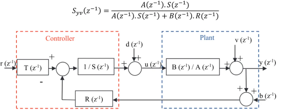
Fig. II-4. Discrete time RST control system 52
Fig. II-5. Discrete time RST control system in presence of disturbances 52
Fig. II-6. Flowchart of RST control synthesis approach 55
Fig. III-1. Structure diagram of USR60[42] 58
Fig. III-2. (a) Polarization of the piezo-ceramic ring , (b) Driving mechanism of TWUSM [42] 59
Fig. III-3. Block diagram of USR60 model subsystems 62
Fig. III-4. Spring-mass-damper representation of the USM stator 63
Fig. III-5. Drawing of stator rotor contact surface [100] 65
6
Fig. III-7.Description of rotor angular motion 66
Fig. III-8. Block diagram of the Simulink model of USR60 67
Fig. III-9. (a) Generated stationary waves, (b) Traveling wave amplitude at 40kHz 68
Fig. III-10. (a) TW amplitude as function of driving frequency, (b) Rotor height 68
Fig. III-11. (a) Half-contact length and stick point locations, (b) Motor generated torque 68
Fig. III-12. (a) Time analysis of motor velocity, (b) Speed-load characteristics 69
Fig. III-13. Speed-frequency characteristic under different load torques 70
Fig. III-14. Speed-Vrms characteristic at different frequency (TL=0 Nm) 70
Fig. III-15. Speed variation as function of voltages phase shift (TL=0 Nm) 70
Fig. III-16. Block diagram of experimental setup 72
Fig. III-17. Experimental platform 72
Fig. III-18. (a) The electromechanical specifications of FAS 21[127] , 72
Fig. III-19. Experimental motor speed variation as function of the driving frequency (TL=0 Nm) 73
Fig. III-20. Experimental motor speed variation as function of the driving frequency under different
load torques 73
Fig. III-21. Motor temperature effect on : (a) Resonance frequency, (b) Rotational speed 73
Fig. III-22. (a) Vfb amplitude versus excitation frequency at various load torques, (b) The motor speed
versus Vfb amplitude at various load torques 74
Fig. III-23. Voltage amplitude effect on the motor speed (TL=0 Nm) 75
Fig. III-24. Experimental motor speed variation as function of the voltage phase shift under different
load torques 75
Fig. III-25. (a) Synoptic of TF identification method, (b) Open loop speed response for π/2 phase shift
step 76
Fig. III-26. (a) USR60 Closed loop configuration, (b) USR60 closed loop augmented by weighting filter
77
Fig. III-27. Frequency analysis of sensitivity transfer functions 78
Fig. III-28. Discrete time USR60 plant controlled by RST regulator 79
Fig. III-29. Bode diagrams of USR60 control systems 80
Fig. III-30. Comparison of closed loop position responses: (a) Step response , (b) Step response with
limited phase shift, (c) Sine-wave motion,(d) Triangular motion 81
Fig. III-31. Controller performances under motor parameters variation: (a) 50% km, (b) 65%τm 81
Fig. III-32. Comparison of position step responses under: (a) Control signal noises, (b) Measurement
noises 81
Fig. III-33. Block diagram of Simulink closed loop system 82
Fig. III-34. Simulation of closed loop responses: (a) Step, (b) Triangular motion, (c) Sine-wave motion
83
Fig. III-35. (a) Comparison of control signal noises rejection capability, (b) Injected noises,(c)
Comparison of measurement noises rejection capability 83
Fig. III-36. Step response of H∞ position controller (TL=0 Nm) 84
Fig. III-37. H∞ response for periodic position trajectory (TL=0 Nm): (a) Triangular motion, (b)
Sine-wave motion 84
Fig. III-38. Step responses of H∞ position controller : (a) With different load torques, (b) Under different
7
Fig. III-39. RST responses: (a) Step motion (TL=0 Nm),(b) Sine-wave motion (TL=0 Nm),(c) With
different load torques 86
Fig. III-40. Comparison of H∞, RST and PID step position responses for loaded motor: (a) 0.1N.m, (b)
0.2N.m 86
Fig. III-42. Comparison of controller performances for sine-wave motion tracking (TL=0.2 Nm) 87
Fig. III-43. Comparison of controller rejection perturbations capability: (a) Control signal noises, (b)
measurement noises 88
Fig. IV-1. (a) Working principle and assembled parts of PAD [138] , (b) PAD prototype [71] 93
Fig. IV-2. The PAD rotation; The red arrow represents the direction of actuation. The shaft is fixed by
a bearing while the ring is free to rotate around it. One revolution of the contact point will cause the
motor shaft to step one tooth [139]. 93
Fig. IV-3: Scalable technology of PAD [71] 93
Fig. IV-4. PAD speed-load characteristics [68] 94
Fig. IV-5. Synoptic of PAD model 95
Fig. IV-6. Equivalent dynamic model of the actuators and the kinematic of ring-shaft system 95
Fig. IV-7. Circular trajectory of the ring and forces on the ring 96
Fig. IV-8. Model of shaft angular motion 96
Fig. IV-9. Working area of the ring; (a) Centered position, (b) Maladjusted position 97
Fig. IV-10. (a): Driving voltages, (b): Actuator charges 98
Fig. IV-11. (a): Linear actuators displacement, (b): Linear actuators forces 98
Fig. IV-12. (a): Rotational speed at 100Hz, (b): Rotational speed at different frequencies 98
Fig. IV-13. Block diagram of experimental setup 99
Fig. IV-14. Experimental setup 99
Fig. IV-15. PAD speed-frequency characteristics in cases of : (a) no-load condition, (b) 2 Nm of load
torque 100
Fig. IV-16. (a) PAD closed loop configuration, (b) PAD closed loop augmented by weighting filters
101
Fig. IV-17. Discrete time PAD plant controlled by RST regulator 102
Fig. IV-18. Bode diagrams of PAD control systems 102
Fig. IV-19. Comparison of step responses ; (a) High rotation speed, (b) low rotation speed 103
Fig. IV-20. Comparison of perturbation rejection capability; (a) Sensor noises (t=0.4s), (b) Control
signal noises (t=0.4s) 103
Fig. IV-21. Experimental H∞ step response (Ω=6 rpm) 104
Fig. IV-22. (a) H∞ response for two motion directions (Ω=10 rpm), (b) H∞ responses at different motor
speeds 104
Fig. IV-23: H∞ perturbation rejection capability, (a) Control signal noises (Ω=6 rpm), (b) Sensor noises
(Ω=6 rpm) 105
Fig. IV-24: RST step responses, (a) Ω=6 rpm, (b) at different speeds 105
Fig. IV-25: RST perturbation rejection capability, (a) Control signal noises, (b) Sensor noises 106
Fig. IV-26. Comparison of controller step responses (a) Under 30Hz, (b) Under 50Hz 106
Fig. IV-27. Comparison of rejection capability of control signal perturbations (Ω=6 rpm): (a) H∞, (b)
RST,(c) PID 107
Fig. IV-28. Comparison of rejection capability of measurement perturbations injected at t=5.8s (Ω=6
8
Fig. V-1. (a) N-310 motor series, (b) Elliptical motion of legs, (c) Working principle of WPZM 114
Fig. V-2. Influence of the voltage amplitude A (V), and phase φ (rad) on the elliptical trajectory of the
drive leg tip 114
Fig. V-3. Block diagram of the closed loop experimental setup 115
Fig. V-4. Experimental platform 115
Fig. V-5. Block diagram of experimental open loop setup 116
Fig. V-6. Open loop motor responses: (a) 2V control signal step, (b) 5V control signal step 117
Fig. V-7. (a) Closed loop configuration, (b) closed loop augmented by weighting filter 118
Fig. V-8. Frequency analysis of Filters and transfer functions behavior 118
Fig. V-9. Discrete time WPZM plant controlled by RST regulator 119
Fig. V-10. Bode diagrams of WPZM positioning system 120
Fig. V-11. Comparison of simulation step responses at different velocities: (a) 1 mm, (b) 10 mm 120 Fig. V-12. Comparison of simulation step responses under model parameters variation: (a) 50% of gain
variation (kw), (b) 50% of constant time variation (τw) 121
Fig. V-13. Comparison of simulation step responses under disturbances: (a) Control signal noises, (b)
Measurement noises 121
Fig. V-14. H∞ experimental and simulation step responses: (a) 0.1mm,(b) 5 mm, (c) 20 mm,(d) 40 mm 122
Fig. V-15. H∞ experimental results under: (a) Different load forces, (b) Real rime speed variation 122
Fig. V-16. Experimental and simulation RST step responses 123
Fig. V-17. RST experimental results: (a) at different speeds, (b) under different load forces 123
Fig. V-18. Comparison of controller experimental step responses: (a) at 2 mm/s speed,(b) at 8 mm/s
speed 124
Fig. V-19. Comparison of controller experimental step responses at different velocities: (a) H∞, (b) RST,
(c) PID 125
Fig. V-20. Comparison of controller experimental step responses under different loads: (a) H∞, (b) RST,
(c) PID 125
Fig. V-21. Comparison of controller experimental responses under a load of 4 N at different velocities:
(a) H∞, (b) RST, (c) PID 126
Fig. VI-1. Prototype of walking motor control board 132
9
List of tables
Table I-1: Characteristics of PZMs ... 39
Table III-1. Variation of the TF parameters ... 76
Table III-2: Stability margins ... 80
Table III-3: Static error as function of load torques ... 87
Table V-1: Comparison of stability margins ... 119
10
Nomenclature
Abbreviations
PZM Piezoelectric Motor PZA Piezoelectric Actuator USM Ultrasonic Motor
TWUSM Traveling Wave Ultrasonic Motor SWUSM Standing Wave Ultrasonic Motor TW Traveling Wave
SW Standing Wave
WPZM Walking Piezoelectric Motor
LSPA Linear Stepping Piezoelectric Actuator RSPA Rotary Stepping Piezoelectric Actuator
PMA Piezoelectric Multilayer Actuator
PAD Piezoelectric Actuator Drive
MRI Magnetic Resonance Imagery
ECM Equivalent Circuit Model
FEM Finite Element Method
TF Transfer Function
PID Proportional Integrator Derivative
FLC Fuzzy Logic Control
NN Neural Network
FNN Fuzzy Neural Network
RC Repetitive Control
BMC Behavior Model Control
COG Causal Ordering Graph
DOF Degree Of Freedom
MRAC Model Reference Adapting Control
PZL Piezoelectric Legs
PI Physik Instrumente
11
Remaining notations
fr Resonance frequency
Vmax Maximum voltage
Vrms Root mean square voltage
φ Phase shift
f Frequency
ω Angular frequency
w Traveling wave amplitude
wmax Maximum amplitude of traveling wave
w1, w2 Amplitude of the standing waves
δ1, δ 2 Vibration amplitudes of the mechanical orthogonal modes
λ Wave length
x0 Half contact length of the traveling wave
xs Stick point location
meff Effective mass of the stator of USR60
Cs1,2 Damping factors of USR60 stator
Ks1,2 Spring coefficients of the USR60 stator
ρ Piezoelectric force factor
k Wave number
Fv1, Fv2 Forces generated by the USR60 stator Ff1,T, Ff2,T Tangential feedback forces
Ff1,N, Ff2,N Normal feedback forces
μ Coulomb friction coefficient
b Inner radius of the stator
h Half thickness of the stator
R0 Middle radius of the contact surface
Rr Radial shape constant of the travelling wave
xr Rotor stiffness per unit area
Mr Rotor mass
z(t) Vertical distance between the rotor and the un-deformed stator surface z0 Initial vertical position of the rotor
FN Generated normal force
12
Ω Angular velocity
θ Angular position
υh,rotor, υh,stator Horizontal velocities of the rotor and stator
Tusm USM generated torque
TL Load torque
Jr Rotor inertia
GUSM(s) Transfer function model of USR60 motor
km Gain constant of USR60
τm Time constant of USR60
dring Diameter of the PAD stator ring
dshaft Diameter of the PAD rotor shaft xa, ya Elongations of orthogonal stacks
rx, ry Cartesian coordinates of the PAD stator ring
Δ x Actuator displacement
d33 Piezoelectric constant
C Equivalent capacitance of the stack
F Stack generated force
Q Electrical charge
U Applied voltage
kx,y Actuators stiffness in x-y directions dx, y Actuators damping factors in x-y directions meff x,y Actuators effective mass in x-y directions
mR Ring mass
mtk Top cap mass
mres Tubular spring mass
Fgx,y, Fax,y Actuators generated and applied forces in x-y directions
a diameter of ring circular trajectory
θs Angular position of the stator
xs,Ys Circular coordinates of the stator
Tact Actuator torque
Ts Stator torque
Tr Rotor torque
Ωr Rotor angular velocity
13
Jtrans Transmission inertia
Jr Shaft inertia
dr Shaft damping factor
itrans Transmission ratio
xadjust, yadjust Shaft deviations in x-y directions GPAD(s) Transfer function model of the PAD
A Maximum voltage amplitude
U1,2,3,4 Driven voltages
GWPZM(s) Transfer function model of the WPZM
kw Gain constant of WPZM
τw Time constant of WPZM
H∞ H-infinity controller
tr Response time
Wi Weighting filter number i
γ Optimal gamma value
K(s) Controller transfer function
14
Thesis outcomes
Publications
International journals
M. Brahim, I. Bahri, Y. Bernard, “Real time implementation of H-infinity and RST motion control of rotary traveling wave ultrasonic motor”, Mechatronics, vol.44, pp.14-23, 2017
M. Brahim, I. Bahri, Y.Bernard, “ H-Infinity and RST Position Controllers of Rotary Traveling Wave Ultrasonic Motor”, International Journal of Mechanical, Aerospace, Industrial, Mechatronic and Manufacturing Engineering, vol: 11, no: 2, pp 323-330, 2017.
M. Brahim, I. Bahri, Y. Bernard, “Design and Implementation of Robust Position Control of Piezoelectric Actuator Drive (PAD)”, Accepted for publication in International Journal of Mechatronics and Automation.
M. Brahim, I. Bahri, Y. Bernard “Design and Real Time Implementation of Robust Position Controller of Walking Piezoelectric Motor’’, submitted to IEEE Trans on Mechatronics
International conferences
M. Brahim, I. Bahri, Y. Bernard, “Piezoelectric Motors in Mechatronic Systems: Electromechanical Performances and Positioning Potentials“, Accepted for presentation in International Conference on Mechatronic and Smart Materials, Paris, November 2017. M. Brahim, I. Bahri, Y.Bernard, “Modeling and Robust Closed Loop Position Controllers of Piezoelectric Actuator Drive (PAD)”, IEEE International Conference on Systems, Automation & Control (SAC), Marrakech, March 2017.
M. Brahim, I. Bahri, Y.Bernard, “H-Infinity and RST Position Controllers of Rotary Traveling Wave Ultrasonic Motor”, 19th International Conference on Control Applications, Amsterdam, February 2017.
M. Brahim, I. Bahri, Y.Bernard, “Modeling and RST Position Controller of Rotary Traveling Wave Ultrasonic Motor”, IEEE Conference on Systems, Process and Control (ICSPC), Malaysia, 2015.
International mobility
2 months (10-11/2016) in the Laboratory of Actuation Technology (LAT), University of Saarland, Saarbrucken, Germany.
Mission: Design and real time validation of positioning experimental platform for linear
15
Résumé en français
I.
Introduction générale
Les moteurs électromagnétiques ont été largement utilisés dans de nombreuses applications d'ingénierie comme actionneurs. Les méthodes de conception, d'optimisation et de fabrication de ces moteurs ont été développées afin d'améliorer leurs performances. Toutefois, en raison des progrès rapides des technologies d'ingénierie, y compris les produits de haute technologie, l'aérospatiale, les équipements médicaux, l'automobile, les robots d’Imagerie par Résonance Magnétique (IRM), des nouvelles exigences des moteurs électriques sont apparues comme la taille réduite, la haute précision, un temps de réponse rapide, une forte densité massique et volumique, et l’insensibilité aux champs magnétiques. Dans ce contexte où la réponse rapide et silencieuse, l’encombrement réduit, et les bonnes performances dynamiques des actionneurs sont appréciées, les moteurs piézoélectriques trouvent leurs places. Ces moteurs se caractérisent en effet par un couple massique important, des forts couples à basse vitesse sans réducteur, une discrétion acoustique dans le cas des moteurs ultrasonores, et ne sont pas affectés par les interférences magnétiques.
Cependant, les phénomènes non linéaires (hystérésis, creep, vibration, dérive thermique…) qui caractérisent leur fonctionnement et les exigences spécifiques de leurs circuits de commande, mettent un frein à leur utilisation et à leur développement. L’alimentation et le contrôle de ces moteurs soulèvent des problèmes liés au comportement capacitif de leur impédance et à la précision des modèles et aux techniques de contrôle qui leurs sont associées.
Pour faire face à ces problèmes de contrôle des moteurs piézoélectriques, deux démarches sont généralement abordées. La première consiste à utiliser des modèles simples tels que les circuits équivalents pour développer des techniques de contrôle non linéaires comme les réseaux de neurones et la logique floue. La deuxième repose sur la connaissance approfondie des comportements réels des moteurs et de leurs principes de fonctionnement, qui débouche sur l’obtention de modèles non linéaires reflétant leur comportement. Cependant la complexité des modèles ou des techniques de contrôle risque d’aboutir à l’élaboration de lois de commande non- implantables en temps réel.
Dans cette thèse, on traite le problème de contrôle en position des Moteurs Piézoélectriques (MPEs) dans des applications à haute précision, et on vise spécialement la robotique, dans le but d’évaluer la faisabilité de réalisation des systèmes de positionnement précis et robustes à base des MPEs dans des applications robotiques, et de dégager les limites de ces actionneurs dans tels applications. Les contributions de cette thèse peuvent être résumées de la manière suivante :
L’établissement de modèles fidèles aux comportements des trois MPEs qui puissent être utilisés pour implémenter des lois de contrôle de position. Les trois moteurs étudiés sont :
Un moteur rotatif ultrasonique à ondes progressives de type USR60 de chez Shinsei.Co.
Un moteur rotatif quasi-statique de type PAD7220 de chez Noliac.
Un moteur linéaire pas à pas de type N-310.13 de chez Physik Instrumente (PI) GmbH.
16
La synthèse des contrôleurs de position précis et robustes des PMEs qui répondent aux exigences d'applications spécifiques des trois moteurs étudiés. Deux contrôleurs sont proposés:
Un contrôleur de type H-infini (H∞) basé sur des filtres de pondérations. Un contrôleur en temps discret de type RST basé sur le placement des pôles.
La garantie des critères de précision, stabilité, et robustesse dans un contrôleur efficace et simple à implémenter en temps réel quelle que soit la topologie du moteur.
La validation des performances de précision et de robustesse des contrôleurs de position proposés sans faire appel ni à des systèmes de compensation supplémentaires des comportements non linéaires, et ni à des techniques d’adaptation des paramètres des contrôleurs pour surmonter le problème d’incertitude des modèles.
La conception de bancs de positionnements expérimentaux basés sur les trois PMEs et l’implantation en temps réel des techniques de contrôle développées. Ces techniques sont comparées expérimentalement à un contrôleur PID conventionnel pour mettre en évidence les avantages des méthodes proposées.
L’évaluation des atouts et des limites des trois moteurs par rapport aux applications robotiques. Les critères d'évaluation sont liés aux topologies des moteurs, aux caractéristiques électromécaniques, aux techniques d'entraînement et aux capacités de positionnement en boucle fermée.
Pour arriver à ces objectifs, une démarche de synthèse des contrôleurs de type H∞ et RST est d’abord mise en place pour un système généralisé dans le second chapitre. Cette démarche est appliquée aux trois MPEs à travers leurs modèles et en respectant les performances des boucles fermées. Les travaux de modélisation et de contrôle en position des moteurs sont présentés dans les chapitres trois à cinq. Des conclusions générales ainsi que des recommandations liées à la modélisation, au contrôle/commande, et aux performances des moteurs étudiés sont présentées à la fin de cette thèse.
II.
Modélisation et Contrôle en position de l’USR60
Le moteur ultrasonique à ondes progressives de type USR60 (Fig.1) est commercialisé par le constructeur japonais Shinsei.Co. Son stator est constitué d’un disque de bronze sur lequel est collé un anneau de céramique piézoélectrique. L'anneau piézoélectrique est divisé en deux phases A et B. Chacune de ces phases est divisée en petits secteurs avec des polarisations opposées. Le principe de fonctionnement est basé sur la superposition des ondes stationnaires générées par chaque phase pour créer une onde progressive qui se propage tout le long de la surface du stator. Les vibrations du stator vont suivre des trajectoires elliptiques (Fig.1.c). Ces micro-vibrations du stator sont transformées en mouvement rotatif du rotor par le biais du principe d’entrainement par frottement.
17
Fig.1. (a) Structure de USR60, (b) USR60 en vue de coupe, (c) mécanisme de contacte stator-rotor
Le modèle proposé de l’USR60 décrit le principe de génération de l’onde progressive, et la surface de contact entre stator et rotor. Celui-ci donne la possibilité d’évaluer la variation des grandeurs de sortie du moteur (vitesse, couple, position) en fonction des paramètres de commande, et les effets de variation des paramètres du stator et de la surface de contact sur les performances du moteur. Ce modèle permet aussi de simuler facilement des lois de contrôles (position, vitesse) en utilisant les amplitudes des tensions d’alimentation, la fréquence, et le déphasage comme grandeurs de contrôle.
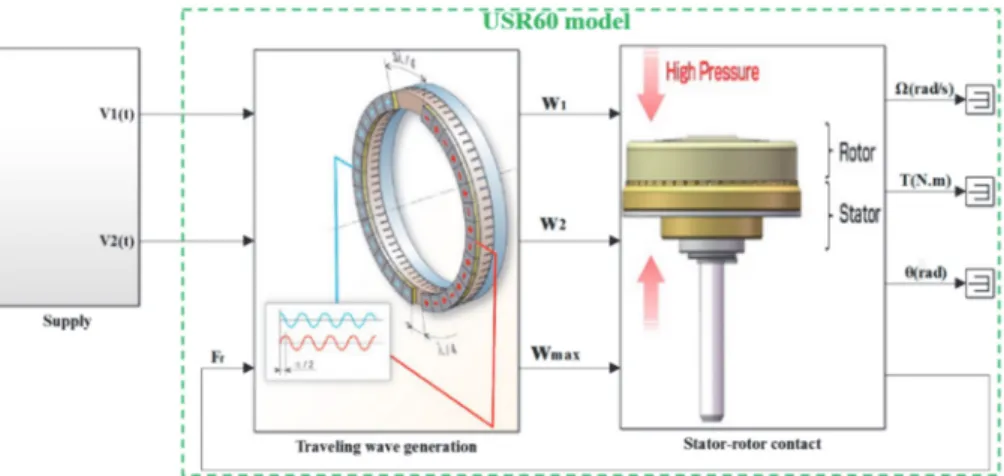
Le modèle de l’USR60 est principalement composé des trois sous-systèmes montrés dans la Fig.2 :
Stator : Dans cette partie on modélise les processus de vibration de l’anneau et la génération de l’onde progressive (W, Wmax).
Mouvement vertical de rotor : l’évolution temporelle de la position verticale du rotor est déterminée dans cette partie ainsi que la longueur de surface de contact entre le stator et rotor (x0). Ce dernier paramètre va être utilisé pour le calcul du couple généré par le moteur (T). Mouvement angulaire de rotor : Le mouvement angulaire ainsi que la vitesse de rotation (Ω)
sont analysés dans ce sous-ensemble.
Fig.2. Synoptique du modèle de l’USR60
Le modèle de l’USR60 est développé sur MATLAB/Simulink comme le montre la Fig.3.
Fig.3. Architecture du modèle de l’USR60 sur MATLAB/Simulink
Stator Rotor (Mouvement vertical) Rotor (Mouvement angulaire) w wmax X0 Xs Ω,T Fn,t Input voltages (a) (b) (c)
18
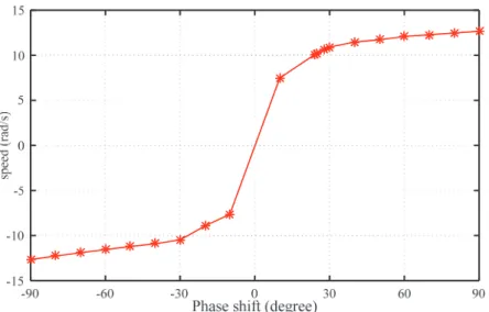
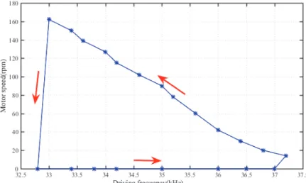
La variation de la vitesse de rotation (Ω) en fonction des paramètres de commande (amplitude de tension, fréquence, déphasage) est simulée afin de choisir la meilleure grandeur de contrôle pour notre système de positionnement. Comme illustré dans la Fig.4, le déphasage entre les deux tensions d’alimentation (φ) est le seul paramètre qui permette de faire tourner le moteur dans le deux sens. Cette grandeur (φ) va être donc utilisée comme signal de control de position de l’USR60 bien que la caractéristique vitesse-déphasage présente une zone morte autour du vitesse-déphasage nul quand un couple de charge est appliqué.
Fig. 4. (a) Caractéristique vitesse-fréquence, (b) Caractéristique vitesse-tension, (c) Caractéristique vitesse-déphasage
Un banc de positionnement expérimental est mis en place pour déterminer les caractéristiques de l’USR60 en boucle ouverte et identifier la fonction de transfert entre la position angulaire du moteur (θ) et le déphasage (φ). Ce banc (Fig.5) va être utilisé aussi pour implémenter en temps réel les lois de contrôle développées à travers la maquette dSPACE.
La Fonction de Transfert (FT) du moteur est déterminée en boucle ouverte en intégrant la relation entre la vitesse angulaire du moteur et le déphasage identifié à partir de la Fig.6. On peut l’écrire sous la forme : ( ) m USM m k θ(s) G s = (s) s(1+ τ s) (1) Avec km= 11.5, et τm=4.25 ms
Fig.5. (a) Synoptique de système de positionnement de l’USR60, (b) Plateforme expérimentale
(a) (b) (c)
19
Fig.6. Variation de vitesse en boucle ouverte pour un échelon de déphasage de π/2
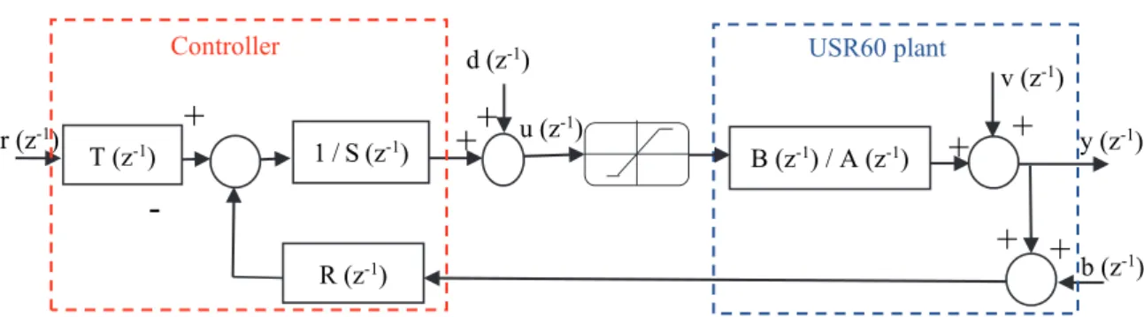
Cette FT est utilisée pour synthétiser un contrôle en temps continu de type H∞, et un autre en temps discret de type RST comme illustré dans les Fig.7.a et b respectivement. Ces deux contrôleurs permettent l’introduction des performances de précision et de robustesse demandées à travers les filtres de pondérations pour le H∞, et à travers le placement des pôles pour le RST.
Fig.7. (a) USR60 contrôlé en position par un H∞, (b) USR60 contrôlé en position par un RST
Les contrôleurs H∞ et RST sont implémentés en temps réel, et leurs résultats sont comparés avec un correcteur PID classique. Les performances du H∞ en terme d’erreur statiques, en présence d’un couple de charge sont meilleures que celles du RST et du PID comme indiqué dans le tableau.1 et Fig.8. La robustesse de ces trois contrôleurs face aux perturbations au niveau des mesures ou au niveau des signaux de contrôle est aussi testée expérimentalement (Fig.9a et b). Ces figurent montrent bien l’avantage de H∞ en terme de rejection des bruits injectés.
Tableau.1: Erreur statique en fonction de couple charge
TL(N.m) H∞ RST PID
0.1 0.1% 0.3% 0.4%
0.3 0.25% 0.6% 1%
0.5 0.4% 1% 1.65%
20
Fig.8. Comparaison des résultats expérimentaux en présence de couple de charge : (a) Echelon de position, (b) Trajectoire
sinusoïdale
Fig.9. Comparaison de la robustesse aux perturbations : (a) niveau signal de contrôle, (b) niveau capteur
III.
Modélisation et Contrôle en position de PAD7220
Le deuxième moteur étudié est un moteur piézoélectrique rotatif commandé avec des fréquences quasi-statiques (loin de la résonance mécanique) de type « Piezelectric Actuator Drive (PAD) » commercialisé par la firme danoise Noliac. Son principe de fonctionnement (Fig.10) est principalement basé sur la conversion des élongations des actionneurs piézoélectriques multicouches en une rotation de rotor moyennant un système d’engrenage mécanique. Ce moteur est alimenté par deux tensions (entre -20 Vmin et 200 Vmax) en quadrature de phase avec une amplitude de 160 Vc-c.
Fig.10. (a) Principe de fonctionnement de PAD, (b) Prototype de PAD7220
(b) (a)
(b) (a)
21
Dans le modèle du PAD, on commence par la modélisation des actionneurs multicouches afin d’obtenir les déformations linéaires orthogonales dans les axes x, et y (Fig.11). La surface de contact entre les actionneurs et l’anneau du stator est ensuite prise en compte, et la transmission de mouvement par engrenage est introduite en dernière étape. Ce modèle permet la simulation d’évolution des grandeurs de sortie du moteur en boucle ouverte (Fig.12), et peut aussi servir pour tester des lois de contrôle en boucle fermée.
Un banc de positionnement expérimental (Fig.13) est mis en place pour déterminer les caractéristiques de PAD7220 en boucle ouverte et pour valider les techniques de contrôle en boucle fermée. Une FT entre la position angulaire du moteur et la fréquence de commande est aussi identifiée expérimentalement : ( ) 2 1 ( ) ( ) 320 PAD rad G s f Hz s (2)
Fig.11. Topologie du modèle de PAD
Fig.12. (a) Déplacements linéaires des actionneurs, (b) Vitesse de rotation à différentes fréquences
Une étude de comparaison expérimentale entre les résultats de robustesse face aux perturbations (mesures et signal de contrôle) des contrôleurs H∞ et RST avec un correcteur PID est abordée. Les figures 14 et 15 confirment l’avantage du contrôleur H∞ par rapport aux deux autres en terme de rejection des bruits.
22
Fig.13. (a) Synoptique de système de positionnement de pad7220, (b) Plateforme expérimentale
Fig.14. Robustesse face aux bruits de mesures :(a) H∞, (b) RST, (c) PID
Fig.15. Robustesse face aux bruits au niveau du signal de contrôle:(a) H∞, (b) RST, (c) PID
IV.
Modélisation et Contrôle en position du N-3101.13
Le troisième moteur étudié dans cette thèse est un moteur piézoélectrique linéaire de chez Physik Instrumente (PI) GmbH, fonctionnant aussi à des fréquences faibles par rapport à la résonance mécanique. Sa topologie est montrée dans la Fig.16, son mouvement linéaire continu est créé par la succession des pas réalisés par les actionneurs piézoélectriques qu’on appelle « pieds piézoélectriques ». Ces pieds entrainent par frottement une tige linéaire pré-chargée avec une vitesse qui peut aller jusqu’à 10 mm/s. Ce moteur est alimenté par quatre tensions déphasées avec une amplitude entre 0 et 45 V, et peut être contrôlé en vitesse et position à travers la fréquence.
Un banc de positionnement expérimental pour le N-310.13 (Fig.17.a) est mis en place pour identifier tout d’abord la FT entre le signal de contrôle (Vc) et la position de la tige (Y). Ensuite, ce banc va servir pour valider expérimentalement les lois de contrôle. La FT est identifiée à partir de la courbe de variation de vitesse en boucle ouverte suite à un échelon de fréquence (Fig.17.b). Cette FT peut s’écrire sous la forme suivante :
(b) (a)
(a) (b) (c)
23 ( ) (1 ) w W PZM c w k Y G s V s s (3) Avec kw= 1.2 mm/V, et τw=0.15 s
Une comparaison expérimentale entre H∞, RST, et PID est abordée pour le positionnement du moteur piézoélectrique linéaire. Les critères de comparaison sont, la précision en présence des diffèrents couples de charges, et à différentes vitesses de déplacements. La Fig.18 montre les résultats de trois contrôleurs quand le moteur est soumis à des forces allant jusqu’à 7.5N. Le H∞ garantit la haute précision quelle que soit la force appliquée, alors que pour les deux autres, on remarque que la précision et le temps de réponse se dégradent en augmentant la force exercée. Le H∞ présente aussi une forte robustesse face au changement de vitesse de déplacement par rapport aux deux autres contrôleurs (Fig.19).
Fig.16. (a) N-310.13, (b) Mouvement elliptique des pieds, (c) Principe de fonctionnement de moteur
Fig.17. (a) Plateforme expérimentale, (b) Variation de vitesse en boucle ouverte pour un échelon de tension de contrôle
(a) (b)
1: One pair is in contact
the rod, the second is lifted off
2: the first pair of the legs is lifted and
bent in the right direction, keeping contact with the rod while the other pair retracts and moves in the left direction
3: The leg pair that was initially retracted now extends to push against the rod while the first pair retracts
4: The cycle is completed with the second pair bending to the right while the first pair is moved left (c)
24
Fig.18. Comparaison des résultats expérimentaux avec différents couple de charges : (a) H∞, (b) RST, (c) PID
Fig.19. Comparaison des résultats expérimentaux avec différentes vitesses : (a) H∞, (b) RST, (c) PID
V.
Conclusion
Dans cette thèse, la problématique de contrôle en position des moteurs piézoélectriques est traitée, afin de valider la faisabilité de réalisation des applications robotiques à haute précision à base des MPEs. Pour arriver à ce but, trois moteurs avec différentes technologies sont testés.
Une démarche de modélisation de ces moteurs a été mise en place, ces modèles permettent à la fois la vérification des comportements des moteurs et l’implémentation des lois de contrôle.
Deux types de contrôles sont ensuite synthétisés, un en temps continu de type H∞ avec des filtres de pondérations, et l’autre en temps discret de type RST.
Trois bancs expérimentaux à la base de ces trois moteurs sont mis en place afin d’implémenter en temps réel les lois de contrôle développées. Ces bancs ont tourné en boucle ouverte dans un premier temps pour évaluer les caractéristiques des moteurs et pour identifier les fonctions de transferts. Les contrôleurs synthétisés sont ensuite implantés en boucle fermée moyennent une carte dSPACE. La précision et la robustesse des systèmes de positionnements à base des MPEs ont été testées sous différentes conditions de fonctionnement.
Ces moteurs piézoélectriques contrôlés en position par le H∞ ont montré une haute précision quelle que soit la charge appliquée (jusqu’à la valeur maximale) et la vitesse de mouvement, sans avoir besoin d’algorithmes d’adaptation des paramètres. La robustesse face au comportement non-linéaire des moteurs et aux bruits injectés est aussi confirmée sans faire appel à des systèmes de compensation supplémentaires.
(b)
(a) (c)
25
26
Traditional electrical motors based on electromagnetic principle have been widely used in many engineering applications as actuators and mechanical power sources. The design, optimization and manufacturing methods of these motors have been developed in order to improve their performances. However, due to the rapid progress of engineering technologies including the high-tech products, aerospace, medical equipment, automotive, semiconductor technologies, and smart robots, new requirements of electric motors appeared such as small size, light-weight, ultra-high precision, fast response, high torque density, and no electromagnetic interferences. Due to the structure and operating principle of electromagnetic motors, it becomes difficult to meet these requirements.
In parallel, the intensive worldwide research efforts in smart materials based actuators and related drive circuits promote the integration of new type motors. The piezoelectric motors are relatively mature among these innovative motor concepts. Where, since the discovery of the piezoelectric effect in 1880, the piezo-system technologies have made rapid progress in terms of reliability, efficiency, and compactness. The piezo-motors benefit from the direct drive principle using the converse piezoelectric effect to achieve interesting performances required in advanced engineering fields. They are well classified to actuate ultra-precision positioning system, where the quick response, small size, and self-locking criteria are important.
As an introduction, this chapter presents an initiation to the piezoelectric technology including the operating principles of piezo-actuators and motors, and the nonlinear behaviors of these devices. The piezo-motors are classified based on various criteria, and the motion generation principle of each category is explained. A survey of the industrial applications of piezo-motors is proposed in order to highlight the importance of these actuators in positioning applications. Finally, the thesis contributions and outlines are highlighted.
I.1 Objectives and scope of the research
In the recent decades, the piezoelectric motors (PZMs) are widely suggested for engineering applications where the high precision, fast response, and compact size requirements are very important. This is mainly due to the electromechanical characteristics of these motors such as the small size, fast response, theoretical unlimited resolution, self-locking, high torque density, and high torque at low speed without gear.
These features make the PZMs a very competitive candidate to the electromagnetic motors for industrial fields and especially robotic applications. In parallel to the precision and fast response potentials of PZMs, let us explain the advantage of high holding torque of PZM without supply. When actuating a robot arm by electromagnetic motor, to avoid the returning to initial position or laying down of the arm in case of off-power, a fail-safe brakes system is applied to stop and hold. These fail-safe brakes systems are generally based on permanent-magnetic and spring-set systems. This additional mechanism leads to an increase of system size and moment inertia, and in consequence slower response time. Due to the driving principles of PZMs, they benefit of their high holding torque without supply to maintain the final position without braking system. In other hand, the non-magnetic characteristic makes PZMs as a promising solution to actuate the Magnetic Resonant Imagery (MRI) robots for surgical operations. Nevertheless, the insertion rate of PZMs into robotic applications do not reflect the real potentials of these motors. These integration difficulties are due to many factors that can be resumed in; the highly nonlinear behavior especially when operating close to the resonance, several sources of nonlinearities in different frequencies operations ranges (hysteresis and creep in low frequency, and vibration in high frequency), the requirement of specific drive system for high capacitive loads (PZMs), and the time-variant motor parameters due to the sensitivity to heating, load torque and electrical noises. Therefore, complexes, time consumption, and adaptive techniques are generally addressed to control the position
27
of PZMs in closed loop operation mode, where an on-line parameters adaptation and additional compensation systems are required to overcome the motor nonlinear behaviors. The application of these methods in practical engineering applications remains difficult.
This thesis aims to study the feasibility of the design and implementation of robust position control of PZMs with different topologies. The control technique should meet the specific requirements of the PZMs robotic applications in terms of accuracy and robustness, and fulfill the simplicity criteria for practical implementation issues. This goal will be achieved through the establishment of electromechanical models of different topologies of PZMs for control purposes. Afterwards, the design and real time implementation of simple, precise, and robust position controllers of PZMs. The strengths and limitations of each piezo-positioning system in terms of control performance and the motor behaviors in open/closed loop operation conditions will be evaluated. This is in order to collect the most required data to design an “ideal” piezoelectric motor for robotic applications as perspective of this research work.
The piezoelectric motors that will be in the scope of this research are in the mechanical power range between 1 and 20 Watts. The output motion is in the range up to 100 mm for linear motors and bidirectional motion for rotary motors. These motors are mainly used to actuate MRI surgical robots, to adjust the driver’s seat in automobiles, and for silent and smooth window operation of a car door. Therefore, in this thesis we will not be interested to the nano/micro-motors nor to the micro-robots based on PZMs.
I.2 Initiation to piezoelectric actuators and motors
I.2.1 Direct and converse piezoelectric effects
The origin of the world piezoelectric is derived from the Greek world “piezo” which means“press”. The piezoelectric effect is the property of some materials to develop electric charge on their surface when a mechanical stress is exerted on them [1], and it was discovered in 1880 by the brother Pierre and Jacques Curie. There are many materials that exhibit a piezoelectric effect, and the lead zirconate titanate (PZT) is the most widely used material. The electrical response of these materials to the mechanicals effort is called direct piezoelectric effect and it is the principle of piezoelectric sensors. The same material can also generate a mechanical stress when an electric field is applied, and this mechanical response is called converse piezoelectric effect (Fig. I-1). The converse piezoelectric effect is at the origin of creation of the piezoelectric actuators.
Fig. I-1. Direct and converse piezoelectric effects
I.2.2 Principle of piezoelectric actuator and motor
As aforementioned, the piezoelectric actuator (PZA) is based on the converse piezoelectric effect. The major drawbacks of PZAs is their small stroke, Amplified Piezoelectric Actuators (APA) [2] and
28
multilayer bending actuators [3] are proposed to increase the actuators full stroke at the expense of stiffness and actuation force. However, the full stroke stills in the range of a few millimeters, even with such structures.
The piezoelectric motor (PZM) consists on the conversion of the limited displacements of PZA into unlimited linear or rotational motion using different mechanical structures and drive principles. The PZMs can be classified into many categories based on the motion type, operation principle, and frequency operation range. The classification and the operation principle of PZM categories will be discussed in the section I.3.
I.2.3 Nonlinearities of piezoelectric actuators
As aforementioned, the piezoelectric motor is mainly composed by one ore many piezoelectric actuators emerged into a mechanical structure to produce unlimited motion. Thus, the nonlinear characteristics of the PZA outputs will generally affect the PZM performances. In this section, an overview of the common nonlinearities of PZAs will be discussed.
The strain of PZA is not only determined by the driving parameters (voltage amplitude, frequency, and phase shift), but it depends on many factors. These factors include the mechanical boundary conditions, especially on the pre-stress of the actuator, thermal drift, and self-heating [4]. The PZA displacement shows also several nonlinear behaviors caused principally by the hysteresis, creep, and vibration phenomena.
I.2.3.1 Hysteresis
Hysteresis is a nonlinear behavior between the applied electric field (u) and the mechanical displacement of a piezoelectric actuator (x) as shown in Fig. I-2. This phenomenon is the cause of irreversible losses that occur when similarly oriented electric dipoles interact upon application of an electric field [5]. The hysteresis effect on the displacement of a piezoelectric actuator is more significant over large range motion. In general, the maximum error caused by the hysteresis can reach 15% of the travel range of the PZA. With the increase of driving frequency, the hysteresis caused errors may go beyond 35% [6].
Fig. I-2. Hysteresis between the applied voltage (u) and the actuator displacement (x)
To treat the hysteresis, many efforts have been made in the literature. The proposed solutions can be classified into feedforward and feedback control techniques. The feedforward techniques (also called inversion-based controls) consist on the modeling of the hysteresis nonlinear behavior, and in second time to apply the inverse model in order to compensate the hysteresis effect (Fig. I-3). Good tracking results can be achieved if the plant model and its frequency response are known with high accuracy [7]. As a consequence several models are proposed to deal with the hysteresis phenomenon. Roughly speaking, the hysteresis model of piezo-actuated stages can be classified into physics-based and phenomenological models [6]. An overview of the hysteresis models of actuated piezo-stages is given in Fig. I-4, and the principle of each modeling approach can be found in [6-9]. However, it is
29
demonstrated that, until now, there is no general reliable model to completely represent the hysteresis behaviors of piezo-actuated stages [6].
The second control approach of the hysteresis in piezo-stages is the feedback control method as illustrated in Fig. I-5. In this configuration, the hysteresis nonlinearity is treated as a nonlinear bounded disturbance or characterized by the aforementioned hysteresis models [6].Then, different feedback controllers can be applied to compensate the hysteresis effect [7].
Fig. I-3. Feedforward control of Hysteresis effect
G
H
H
-1 Dynamic model Hysteresis model Inverse hysteresis model Piezo-actuated stage x x* u Hysteresis models Phenomenolog-ical models Physic-based models Jiles-Atherton model Differential-equation based models Operator-based hysteresis models Other hysteresis models Domain wall modelDuhem model Backlash-like model Bouc-Wen model Krasnosel’skii-Pokrovkii model Preisach model Prandt-Ishlinski model Nero/fuzzy model Polynomial model Ellipse based model
30
Fig. I-4. Classification of hysteresis models for piezo-actuated stages [6]
The major drawback of these techniques is the limitation of the closed loop bandwidth of the positioning system in presence of highly resonant modes.
The feedforward and feedback controllers can be combined to deal with the compensation of hysteresis nonlinearity in piezo-actuated stages as shown in Fig. I-6. With this methodology, the inverse compensators with different models are applied in the feedforward part and the feedback controllers are simultaneously designed in the feedback loop to mitigate the effect of the inversion errors and to handle the remaining dynamics of the systems [6].
Fig. I-5. Feedback control of Hysteresis effect
Fig. I-6. Feedback-feedforward control of Hysteresis effect
There is also a hardware solution to reduce the hysteresis nonlinear behavior of piezoelectric actuators which is the use of charge amplifierrather than voltage amplifier. By using charge drivers and through the regulation of the piezoelectric current or charge, significant reduction of hysteresis effect can be achieved [10-12]. However, the capacitive behavior of piezoelectric actuators complicates the design of charge driver due to the finite output impedance and dielectric leakage [7].
I.2.3.2 Creep
When a voltage step change is sent to drive a piezoelectric actuator, the response consists on a fast dynamic transient followed by low frequency drift (Δy) of the final position known as creep (Fig. I-7). As shown in Fig. I-7, the creep effect becomes noticeable over extended periods of time, where large position errors are produced with the increase of time. Therefore, the creep can particularly degrade the static positioning potential of piezoelectric actuators.
G
H
Feedback controller Dynamic model Hysteresis model Piezo-actuated stage x x* u + -G
H
Feedback controller Dynamic model Hysteresis model Piezo-actuated stage x* u + - x Feedforward controller31
Fig. I-7. Effect of creep in piezoelectric actuator displacement
The creep effect can be avoided by driving the piezo-stage at high speed, but this operation limits the use of piezoelectric positioning systems in slow and static applications. As done with the other nonlinearities sources, feedback [13-15] and feedforward [16, 17] controllers are proposed to compensate the creep effect. To describe this phenomenon and to apply the compensation control methods, creep models are reported in the literature. One of them is usually called logarithmic model, and it can be expressed by the following equation [6]:
1 I-1
Where y(t) is the displacement of the piezo-actuator when subjected to a fixed input voltage, t0 is the time at which the creep effect is obvious, y0 is the displacement at the time of t0 after applying the input voltage, and γ is a coefficient determining the rate of the logarithmic response. Generally, y0, t0, and γ are identified experimentally.
I.2.3.3 Vibrational dynamics
The dynamic vibration of piezoelectric devices is a relatively high frequency nonlinear behavior. The vibration effects are mainly caused by exciting the resonance modes of the piezo-actuated stage. Due to the high stiffness and low structural damping ratio of piezoelectric actuators [6], a sharp peak of the damped structure emerges in the frequency response of the piezo-actuated stages as shown in Fig. I-8.a. The vibrational dynamics have a low-gain margin problem because of the rapid phase drop associated with the small structural damping ratio and hysteresis nonlinearity [18, 19]. In consequence, the high frequency input signals can easily excite the motion vibration and tracking errors will be obtained as shown in Fig. I-8.c. Thus, the dynamic vibration is the main factor limiting the bandwidth of piezo-positioning stages. To overcome this problem, several vibrational dynamic models are proposed. The concept consists of neglecting the hysteresis effect, and linear dynamic equations are identified using the input and output data of the piezoelectric system [6].
The common feedforward control of vibration is the model-based control method by inverting the linear dynamic model of the piezo-actuated stage and without considering the hysteresis effect [18, 20, 21]. The input shaping method is alternatively proposed to deal with the dynamical vibrations problems [22, 23]. The notch filter [15], integral resonant [24], and positive feedback [25] controllers are also tested to compensate the dynamical vibration effects and to increase the piezo-stage bandwidth.
Δy
y y0
32
Fig. I-8. Vibration effect: (a) Frequency response, (b) Tracking results at 1 rad/s, (c) Tracking results at 20 rad/s
I.3 Classification of piezoelectric motors and operating principles
The piezoelectric motors can be classified according to different criteria including the motion type (linear, rotational), frequency operation range, stator geometric, and operating principle [4, 8, 26-28]. In this report, the PZMs are classified in sub-categories in order to integrate the most used criteria as shown in Fig. I-9. In the first level of Fig. I-9, the PZMs are classified based on the motion type into linear or rotary motors. These two types of PZMs can be classified according to the frequency operation range into quasi-static and ultrasonic motors. Two categories of quasi-static PZMs can be distinguished based on the driving method, which are the stepping and inertia motors.
The operating principle of the inertia motors is based on the stick-slip drive method, while the commercialized stepping PZMs can be devised into inchworm and walking principle motors. The ultrasonic motors (USM) are classified as function of the wave propagation method into traveling and standing waves USM.
(a)
33
Fig. I-9. Classification of piezoelectric motors
I.3.1 Quasi-static piezoelectric motors
The quasi-static motors are the piezoelectric motors driven in a frequency range much lower than their mechanical resonance frequencies. These types of motors are principally characterized by the theoretically unlimited resolution at low speed without gear. The quasi-static PZMs are driven based on the inertia and steeping methods. In the following two sub-sections, the characteristics, and operating principles of the two PZM categories will be reviewed.
I.3.1.1 Inertia motors
Compared to the others PZMs, the inertia motors have a simply mechanical design, and are typically driven by one electrical voltage. These characteristics favorite the miniaturization of inertia motors for very compact positioning systems.
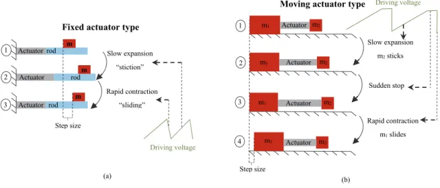
The inertia motors use the inertia of the driven part to drive it through an uninterrupted friction contact to generate motion [4]. These motors are driven by asymmetric voltages to create the transition between the static (stick) and sliding (slip) friction, which explains the name “stick-slip” given to inertia PZMs. There are two basic functional principles of inertia motors, one with fixed actuator, and the second with moving actuator (called also impact drive motor). The operating principles of the two types of inertia motors are illustrated in Fig. I-10.
In the inertia drive PZM incorporating fixed actuator two movement stages can be distinguished. As shown in Fig. I-10.a, the actuator expands slowly and the slider follows this movement due to static friction. Next, the actuator contracts rapidly so that the slider is unable to follow this movement and lets the actuator slip back due to its own inertia and the not sufficiently high dynamic friction. The motion direction is determined by the mode of the slow movement (expansion or contraction).
Piezoelectric motors Rotary Linear Ultrasonic Stepping Quasi-static Motion type Frequency range Wave propagation method Driving
method Inertia Traveling
waves Standing waves Inchworm Walking Operation principle Stick-slip
34
Fig. I-10. Description of inertia motor principles: (a) Fixed actuator type, (b) Moving actuator type
The inertia drive PZM based on moving actuator (impact drive motor) is typically composed by three main parts: the main body (m2), the actuator, and the inertia weight (m1). The main body is in frictional contact with a guiding surface, the actuator and the weight do not touch this surface (Fig. I-10.b). When the actuator expands (or contracts) slowly, the inertial weight moves with it, while the main body maintains its position due to the high friction force compared to the inertia force. This expansion is stopped suddenly to overpass the static friction, and immediately a rapid contraction of the actuator follows which causes impulsive inertia force to be exerted on the main body. As consequence, the main body follows the motion direction of the actuator. At the end of this cycle, one motor step motion is generated. In order to change the motion direction, the slope of the driving voltage will be inverted (rapid expansion and slow contraction). The first experimentally validated inertia PZMs are proposed firstly by Pohl in 1986 [29] and by Higuchi et al. [30]. There are others little different topologies of inertia motors derived from the two aforementioned principles, which are reported in the literature [4, 26, 31].
I.3.1.2 Stepping motors
The piezoelectric motors based on stepping mode are also called clamping-based motors. As the name reflects, these motors are based on the succession of clamping and unclamping movements. Depending on the operating principle and the employed moving parts, two categories of stepping PZMs can be distinguished, which are the inchworm and walking PZMs. This kind of motors are characterized by the unlimited resolution with high force capability, and it suffers from the low speeds.
Inchworm PZMs
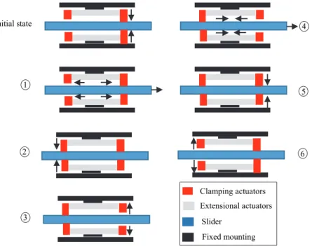
The first clamping-type PZM working with inchworm principle was developed and commercialized by Burleigh Instruments, Inc. in 1974 [32]. The basic structure of inchworm motor consists of three piezoelectric actuators; two are used for clamping and one for extension [33, 34]. In order to obtain continuous motion and higher forces, similar designs of clamping motors with five actuators are proposed [35, 36]. The topology and the clamping sequences of the inchworm motor are illustrated in Fig. I-11. The slider is initially clamped by one of the clamping actuators. In step 1, the extensional actuator expands allowing the slider to move away from the open clamp. In steps 2 and 3, the switching between the closed and open clamps is subsequently realized. When the extensional actuator contracts in step 4, the distance between the clamps reduces and the slider moves further in the same direction. The clamping actuators change their roles again and a new cycle starts in steps 5 and 6 respectively.
Step size Actuator Actuator Actuator rod rod rod m m m 1 2 3 Slow expansion “stiction” Rapid contraction “sliding”
Fixed actuator type
(a) Driving voltage Step size m2 1 2 3 Slow expansion m2 sticks m1 Actuator m2 m1 Actuator m2 m1 Actuator Sudden stop m2 m1 Actuator 4 Rapid contraction m1 slides (b) Driving voltage
![Fig. I-17. Concept of PIline ultrasonic motor series from Physik Instrumente GmbH [48]](https://thumb-eu.123doks.com/thumbv2/123doknet/14699922.746811/41.892.215.689.734.925/concept-piline-ultrasonic-motor-series-physik-instrumente-gmbh.webp)
![Fig. III-2. (a) Polarization of the piezo-ceramic ring , (b) Driving mechanism of TWUSM [42]](https://thumb-eu.123doks.com/thumbv2/123doknet/14699922.746811/62.892.145.742.114.341/fig-iii-polarization-piezo-ceramic-driving-mechanism-twusm.webp)