RESEARCH OUTPUTS / RÉSULTATS DE RECHERCHE
Author(s) - Auteur(s) :
Publication date - Date de publication :
Permanent link - Permalien :
Rights / License - Licence de droit d’auteur :
Bibliothèque Universitaire Moretus Plantin
Institutional Repository - Research Portal
Dépôt Institutionnel - Portail de la Recherche
researchportal.unamur.be
University of Namur
IODASS Method DAD architectural language & ASR requirement language
-Technical Report
Gilson, Fabian
Publication date: 2010
Link to publication
Citation for pulished version (HARVARD):
Gilson, F 2010, IODASS Method - DAD architectural language & ASR requirement language - Technical Report..
General rights
Copyright and moral rights for the publications made accessible in the public portal are retained by the authors and/or other copyright owners and it is a condition of accessing publications that users recognise and abide by the legal requirements associated with these rights. • Users may download and print one copy of any publication from the public portal for the purpose of private study or research. • You may not further distribute the material or use it for any profit-making activity or commercial gain
• You may freely distribute the URL identifying the publication in the public portal ?
Take down policy
If you believe that this document breaches copyright please contact us providing details, and we will remove access to the work immediately and investigate your claim.
DAD architectural language & ASR requirement language
Technical Report
Version 0.1
Fabian Gilson
PReCISE Research Center
Faculty of Computer Science
University of Namur
December 4, 2010
Contents
1 Introduction 2
2 Addressed Problem 2
3 IODASS method and languages overview 2
3.1 Prerequisites to the method . . . 4
3.2 Architectural models . . . 4
3.3 Architecturally-significant requirement models . . . 4
3.4 Architecture transformations . . . 5
3.5 Construct semantics refinement mechanism . . . 5
4 Definition-Assemblage-Deployment 6 4.1 Graphical syntax . . . 6
4.2 Textual syntax . . . 7
4.3 Language metamodel and concepts . . . 8
4.3.1 Interface-related constructs . . . 8 4.3.2 Definition constructs . . . 10 4.3.3 Assemblage constructs . . . 12 4.3.4 Deployment constructs . . . 12 5 Architecturally-Significant Requirement 13 5.1 Graphical syntax . . . 13 5.2 Textual syntax . . . 14
5.3 Language metamodel and concepts . . . 15
6 Requirement formalisation guidelines 16
7 Conclusion and future work 17
A A more complete example: a distributed image renderer 19
A.1 First models and hypothesises . . . 20
A.2 A simple requirement implementation . . . 21
A.3 Functional alternatives of the Job Synchronisation requirement . . . 21
A.4 Implementation possibilities of the DoJob interface . . . 22
A.5 Infrastructure constraints implementation . . . 22
B DAD grammar 25
C ASR grammar 29
Revision history
0.1 Initial creation (complete rewriting from old technical report)
1
Introduction
The present document gives an overview of the IODASS method. IODASS is a transformation-oriented method supplied for component-based architecture design and maintenance. It consists in three inter-twined languages, an Architecture Description Language (ADL), an architecturally-significant require-ment language and a model transformation language. This report focuses on the concepts of the method and details the architectural and requirement modelling languages.
We first start by explaining the problem addressed by our work in Section 2. Then, we give an overview of the concepts behind IODASS models in Section 3. Next, we present the graphical and textual syntaxes of architectural models and explain the language metamodel in Section 4. In Section 5, we introduce the graphical and textual syntaxes for requirement models and detail the language metamodel. Next, we give formalisation guidelines for such requirements. We finally conclude in Section 7. In Annex A, the reader can find a larger illustration of the method based on an academic example where we implement and modify iteratively a distributed image renderer. The architecture description language grammar is presented in Annex B. The grammar of the requirement modelling language is given in Annex C. Both grammars are expressed as LL(1) grammar in an EBNF-based language.
2
Addressed Problem
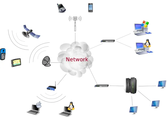
Nowadays information systems (IS) become larger, decentralised and integrate Commercial Off-The-Shelf (COTS) components. Moreover, such systems often have to deal with existing hardware that is heterogeneous in calculation power, memory capacity, connection capabilities and so forth. Also, components may be constrained by many non-functional requirements, such as efficiency (mainly quality of services), reliability or portability. We illustrate this problem in Figure 1.
IS have to deal with evolving requirements and technologies that impact on the architecture itself. Also, as system architectures are modified to cope with changes, the system history should be traced in order to keep track of design decisions that can be reused to face recurrent problems. Then, there is a need for integrating architectural models and design decisions that created these models.
3
IODASS method and languages overview
We present here an iterative design process that intertwine information systems architecture and architec-turally significant requirements. The method relies on two modelling languages and one transformation language. IS architectural elements are represented with a three-layer architecture description language (ADL) showing the components, their interfaces and their relations, as well as their architectural and deployment constraints. Architecturally significant requirements (ASR) are presented in a summarized
model where each architecture construct is linked to its requirements and the design decision that imple-mented these requirements. The design decisions are expressed as model transformations. Each language is detailed in the following sections, as well as the refinement mechanisms for modelling construct se-mantics.
3.1
Prerequisites to the method
As a starting point, preliminary requirement engineering tasks must be performed in order to highlight a set of needed prerequisites.
The architectural coarse-grained components must be defined or translated into the ADL. Depen-dencies between components can be expressed either as usage relationships or provide-require contracts. Usage relations offers more flexibility when coupling components if the the provide-require contract is not defined yet or undocumented. The communication protocols supporting the connections must be spec-ified or translated as architectural constructs too. Also, the existing hardware units (computer, router, network cable, etc) must be specified using the ADL. Their properties and constraints are defined with at-tributes. Planned deployment infrastructure constraints are expressed analogously to existing hardware. The hardware definition can be completely or partially skipped at first.
The list of architecturally-significant requirements must be linked to the architectural elements in charge of their implementations. Functional requirements must focus on the services used or implemented by components. Non functional requirements must have a meaning on the architecture model, relate to identifiable constructs and express constraints such as efficiency or reliability constraints. They are formalised regarding the language guidelines presented in Section 6 and summarised in a dedicated ASR model.
Both modelling languages are presented in the following sections.
3.2
Architectural models
IODASS architectural models are presented as a three-layer model. First, the Definition layer specifies platform-independent abstract object types. These object types are linked together either by usage relationships or provide-require contracts. Basically, functionalities of the object types are expressed as method signatures that are grouped in interfaces. Their connection capabilities are constrained by a set of accepted communication protocols. We separate connectors and protocols in order to provide a wider range of connection possibilities. Connectors define how objects are connected and protocols focus on how they communicate. The object types can be tagged by quality attributes (concerning efficiency, reliability or portability, as classified in ISO/IEC 9126 standard [fS01]) and they are used to specify or select existing pieces of software that conform to their service specifications.
Second, the object types are incarnated as sets of instances that express the minimum and maximum instances of an object type that can be present in a model instance at runtime. The instances and connec-tions can be tagged with platform specific key-value attributes, such as the implementation technology, programming language, hardware requirements and so forth. This stage is called the Assemblage.
Third, we map the instances and connections to the infrastructure where the application will be deployed on (computers, communication media, chipsets, etc.). The infrastructure construct semantics is also refined by attributes in order to express deployment and hardware constraints such as available disk space, cpu power, link bandwidth, supported communication protocols, etc.
3.3
Architecturally-significant requirement models
ASR models are used to capture and keep track of architecturally significant functional and non-functional requirements (ASR), as well as their impacts on architecture models. These requirements must be fully descriptive, non ambiguous and related to only one architectural construct. This model element will be in charge of the implementation of the ASR. ToDo justify why only one
Functional ASR may influence component services specifications and non functional ASR may express architectural constraints concerning reliability, portability or efficiency as defined in the ISO/IEC 9126 standard [fS01].
An ASR is then described at least by a short and a full descriptions, the construct in charge and an ID. But other attributes can also be added such as a priority index. A higher order requirement can be refined into lower order ones. All ASRs are summarised in a UML Use Case-like [Obj09a] graphical model. When an ASR is implemented, it is linked to one (set of) model transformations that weave the requirement implementation into the model. We do not address requirement analysis and refinement phases, but provide a tool for design decision traceability expressed as model transformations.
3.4
Architecture transformations
For each unimplemented ASR, we define a set of model transformations that implement the requirement. Such transformations can be refinement of construct semantics, pattern weaving, construct substitution, etc. This way, any change in the architecture is expressed as model transformations, enabling design decisions tracking and backtracking possibilities to previous models. Furthermore, as any change in the system design focuses on an identifiable part of the architecture and concern a specific requirement, we intend to highlight more accurately possible architectural inconsistencies or threats, like, Quality of Service property violations, deployment incompatibilities, and so forth.
We point out here two major challenges of the transformation language. First, the transformation language should enable the possibility to define reusable transformations for recurrent problems. Second, the language should enable to come back to a previously created model, take another design decision at that point (i.e., define another transformations set) and re-propagate the remaining transformation on the newly created model.
3.5
Construct semantics refinement mechanism
Properties can be defined for many modelling constructs. This attribute mechanism allows designers to refine the construct semantics with domain specific or hardware-related properties. These attributes have two goals: tagging a construct with some properties and validating deployment compatibilities. First, by annotating constructs with properties, we intend to raise the model documentation and clarity because important assets of constructs are directly shown on the model itself. Second, quality attributes can be added to a component and hardware-related specifications to its deployment target in order to check the feasibility of the specified quality attribute. In order to enable this feature, a proper attribute definition mechanism must be created where designers can specify the attribute value type, range and validation rules.
Some constructs can inherit from previously defined constructs of the same type. This is mainly the case for communication protocols, components or hardware. For example, we can have a remote procedure call (RPC) protocol that is refined later into a CORBA protocol [Obj08]. Another example is a web client component refined into a secured web client. As a last example, one can have a specific personal computer extended by another one with a larger hard disk drive or faster CPU.
As highlighted in [BJPW99], behavioural specification of component services and communication protocols must be expressed in an abstract way for many purposes. Modellers can write a minimal behavioural specification for an abstract component and refine it for its concrete implementation in order to enhance implementation flexibility. The specifications will be used by developers to know exactly the aim of a service and will help for test cases writing. Also, a set of property checks can be performed on such representations instead of working on the code itself. Likewise, one can ensure that different implementations of the same construct type are acting in the same way, so comply to the same specifications.
4
Definition-Assemblage-Deployment
In order to give a more concrete illustration of DAD models, we first give a sample graphical model and its corresponding textual representation. Then, we present the language metamodel and details the language concepts.
4.1
Graphical syntax
We created a UML profile as a quick graphical representation for our models. We chose to use UML profile for three main reasons. First, it is pretty handy and fast to create a DSL above UML since it provides a wide range of constructs that can be extended. Second, a large set of existing tools exists for UML diagrams. These tools can often handle profiles as domain specific languages and provide diagrams customisation possibilities with user defined profiles. Third, the major part of these tools can transform UML profiles into XML Metadata Interchange1 files or Meta Object Facility2-compliant models, so the
custom profile can be imported into another tool without too many difficulties and rework.
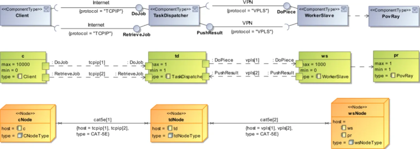
The Figure 2 shows an example of the graphical syntax of DAD models. We highlighted the three parts of the model with dashed rounded boxes. We also decided to use different colours and shapes for each parts in order to be able to identify them from each other if we want to show only one specific part of DAD models.
Figure 2: DAD graphical syntax sample
First, at the Definition level, we specify the types of component and connectors that will be used in the architecture model. Component types are connected through an interface (named Facet, here) in a provide-require manner. The interface can restrict the set of accepted communication protocols. The connection is typed by a connector type that supports a set of protocols. The connector type defines how the component types will be connected with multiple instances of the component type will be created: one-to-one, one-to-many or many-to-many3. This first part is used as a model template for the concrete
architecture.
1Object Management Group (OMG) standard for metadata exchange 2OMG standard for model-driven engineering
Second, the component types are incarnated as sets of instances, restricting the amount of instances that can be present during the architecture lifetime. Interfaces are replaced by port-to-port unidirectional connections, typed by the connector types. A specific protocol can be chosen in the union set of accepted protocols by the connector type and by the interface. This part models then the concrete system architecture with concrete instances that can appear and disappear during the IS lifetime.
Last, the deployment infrastructure is represented in terms of geographical sites, hardware nodes and communication media. The sets of instances are abstractly mapped onto the infrastructure elements in order to perform a set of verifications such as the compatibility between communication protocols and supporting hardware (for example, if a specific Remote Procedure Call protocol is used and a aggressive firewall with restricted opened ports is present on the communication path, the communication will not be possible).
Note that we did not show all existing modelling construct in these samples in order to stay concise. All available building blocks with their properties will be detailed in Section 4.3.
4.2
Textual syntax
For the textual syntax, we decided to use an Eclipse plug-in called Xtext4 for two main reasons. First,
Eclipse has a large community of developers and users. Therefore, lots of plug-ins are available to build tooling support for our method (like for graphical modelling, DSL building, code generation, code analysis, model transformation, etc). Second, the Xtext plug-in generates a customisable textual editor from an EBNF-based LL(1) grammar. The grammar can either be developed from scratch or from the DSL metamodel (translated into an Eclipse modelling language close to the OMG MOF language). Xtext is based on the Eclipse Modelling Framework, so it enables to use the whole EMF-based plug-ins to manipulate models (a.o. graphical DSL builders and code generators ans transformation facilities). The generated tools are Eclipse plug-ins, so perfectly integrated into the Eclipse framework.
The Listing 1 shows the same model as presented in Figure 4 with the textual syntax. The textual model is more complete and detailed than its graphical representation, but is also less intuitive. The three parts are identifiable with the keywords Definition, Assemblage and Deployment. The same constructs as in the graphical representation are present, but with more details.
dadmodel d a d s a m p l e { d e f i n i t i o n { 5 p r o t o c o l P r o t o c o l { a n A t t r i b u t e : ” a V a l u e ” ; } connectortype ConnType { 10 accepts P r o t o c o l ; mode one2one ; } i n t e r f a c e F a c e t { 15 sync boolean do ( i n s t r i n g a S t r i n g ) ; accepts P r o t o c o l ; } componenttype S e r v e r { 20 implements F a c e t ; } componenttype C l i e n t { uses F a c e t ; 25 }
connect C l i e n t : : F a c e t to S e r v e r : : F a c e t with ConnType ; }
30 assemblage {
s o i s [ 1 1 ] : S e r v e r ; s o i c [ 0 1 0 0 ] : C l i e n t ;
connector conn : ConnType p r o t o c o l P r o t o c o l ;
35 connect c : : F a c e t to s : : F a c e t with conn ; } deployment { 40 node CNodeType { a n A t t r i b u t e : ” a V a l u e ” ; } s i t e S i t e { 45 a n A t t r i b u t e : ” a V a l u e ” ; }
node SNodeType extends CNodeType { a n A t t r i b u t e : ” a V a l u e ” ; 50 } medium MediumType { a n A t t r i b u t e : ” a V a l u e ” ; } 55 d e c l a r e cNode : CNodeType ; d e c l a r e sNode : SNodeType ; d e c l a r e Medium : MediumType ; 60 deploy c on cNode ; deploy s on sNode ; deploy conn on Medium ; }
}
Listing 1: DAD model textual syntax sample
The semantics of a number of construct is refined using key-value pairs. This is mainly the case for communication protocols and deployment nodes and media. As discussed in Section 3.5, this will be used for documentation and verification purposes. Interface services are specified by method signatures with the calling type (synchronous or asynchronous), the parameters and return value type. When a component type provides (resp. requires) an interface, we use the keyword implements (resp. uses). The connection between component types is expressed by a connect statement. The sets of instances are declared and concretely connected in the second part. Last, the infrastructure nodes and media are specified, instantiated and linked to the sets of instances and connectors they are intended to host.
4.3
Language metamodel and concepts
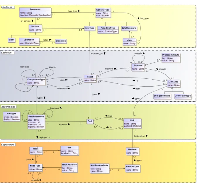
Now we gave an overview of DAD models, we will detail here all the modelling constructs. Figure 3 shows the metamodel of the DAD language. The concepts of the three parts of DAD models are expressed on the same metamodel since they are all used to build one model. We insist here on the fact that they all belong to one model, so one modelling language.
4.3.1 Interface-related constructs
We will first discuss the model construct related to services and data types.
GenericType (abstract)
GenericType is a technical abstract supertype of PrimitiveType, DataStructure and Interface. Interfaces are considered as GenericTypes so they can be used as Service Parameters or Data types. When a GenericType is used to type a specific data, it can be flagged as being an array.
Figure 3: DAD metamodel
PrimitiveType
A set of primitive types are predefined in DAD models. At present time, we introduced as Primitive-Types boolean, integer (signed 32 bit), float (single-precision floating point5), string, char (16 bit uni-code), byte. The DAD PrimitiveTypes specifications are copied from the Java primitive type specifi-cations.
DataStructure and Data
Custom data structures are defined in DAD models as DataStructures containing one or multiple Data. A Data is typed by a GenericType and has a identifying name inside the DataStructure.
Service (abstract)
A Service is a computational block that performs some work. This process can be of three types: an Operation an Event or an Exception.
Operation
An Operation is a Service offered or needed by a resource that must be explicitly called. The type attribute says if the Operation is synchronous (the caller’s execution flow is blocked during the execution of the Service) or asynchronous (the caller can continue its execution flow after the initiation of the call). An Operation can have Parameters and raise one or more Exceptions.
Event
An Event is a structured message triggered by some behavioural conditions that a resource sends out. Events can also have Parameters.
Exception
An Exception is a special structured message indicating that normal execution flow of a Service could not be followed. Exceptions can have Parameters.
Parameter
A Parameter is a data used in a Service. It can be of four types for Operations:
in the Parameter is used as input and passed by value.
out the Parameter is used as output and passed by reference. The value present in the parameter at calling time is not used.
inout the Parameter is used for both uses and passed by reference. result the Parameter is used to send the result of the Operation.
For Events and Exceptions only in parameters can be used.
Interface
An Interface is used to group correlated Services together.
4.3.2 Definition constructs
We will now discuss the model constructs used for the Definition model part.
Facet
A Facet is the materialisation of an Interface. By materialisation, we mean that the Interfaces are implemented or used by a resource present in the architecture model. A local alias can be defined for a Facet. A Facet has a set of supported Protocolsthat restrict the communication facilities via this Facet.
ComponentType
The ComponentType is an identifiable unit (resource) that implements and/or uses one or more Interfaces. It is specified by two mechanisms: its Interfaces and quality attributes (used to refine and document its semantics). A ComponentType can be part of another one and will be used to type one or more concrete instances (see SetofInstances). A ComponentType can inherit from one or more Component-Types. Two ComponentTypes can be related by a usage relation. This kind of unidirectional relationship is used to relate two ComponentTypes without using a structured Interface. This is particularly useful when using COTS components conforming to the same specification but with different interfaces and/or communication protocols.
Protocol
A Protocol denotes properties of the communication protocol that will be used for the connection between ComponentTypes(and also SetofInstances). This allow designers to externalise the commu-nication protocol specificities and make Facets more technology-independent. In order to reflect com-munication protocol hierarchies, a Protocol can extend another so that it inherits the properties of its parent and define new ones. For example, a Transmission Control Protocol (TCP) Protocol can be extended by a Secure SHell (SSH) Protocol.
ProtocolAttribute
In order to refine the semantics of a Protocol, one or more ProtocolAttributes can be defined. They consists in a pair key-value. The attribute mechanism is discussed in Section 3.5.
LinkType (abstract)
A LinkType is an abstract object used to type the connection between two ComponentTypesthrough their compatible Facets. LinkTypes accepts a set of Protocols as means to make distinct the communication layer and the transport layer. We define two types of LinkType: DelegationType and ConnectorType.
DelegationType
A DelegationType connector is used when an ComponentType delegates part of its job (i.e., one or more Facets) to a child ComponentType(called a delegate). We connect here two Facets of the same type (implements-implements or uses-uses). Five types of DelegationType strategies exits in DAD models6.
Simple is allowed only when one delegate is in charge of A parent Facet˙Incoming calls to implemented Services are forwarded to the delegate.
Broadcast incoming calls to implemented Services are forwarded to all delegates. The boolean attribute forward-all says if all responses are forwarded to the caller when a result must be sent back, otherwise only the first computed response is transmitted.
Random the call is forwarded to one randomly chosen instance. RoundRobin the instances are handling the request each one in turn.
LoadBalancing a user-defined load balancing strategy is implemented to optimise the request han-dling performance. This strategy is identified by a name.
ConnectorType
ConnectorTypes are used to connect a implemented Facet to its compatible used one. We have three types of ConnectorTypes:7
One2one connectors express the possibility for each instance of a ComponentType to be connected to all destination ComponentTypes via a point-to-point link.
One2many connectors are used to connect two ComponentTypes where each source instance can be connected to multiple destination instances. We will have a communication link between each origin and (possibly) all destinations. It can be implemented by a broadcast communication or if the ConnectorType is said to be distributive, it will become a point-to-point link between the origin and all destinations or some kind of multicast connection. This communication mode do not allow Operations return values.
Many2many connectors are used when multiple instances at the origin can be connected to multiple instances at the destination. All origins are broadcasting to all destination instances. No return value is allowed when using this communication mode.
4.3.3 Assemblage constructs SetofInstances
The SetofInstances express the set of object(s) implementing a ComponentType. It has a minimum and a maximum cardinality expressing available slots for instances of a SetofInstances. It can be managed by other SetofInstances for its creation and/or destruction and has a boolean value called bigBang telling if the SetofInstances is created by a human intervention. This is used to tag the SetofInstan-ces that need to be present in order to have a runnable architecture, i.e. in order to know what are the objects that must be instantiated by a manual action when starting up the whole application. The manages relation and bigbang attribute are used to describe how an architecture must be deployed and started at runtime.
Link
A Link is the concrete connection between two SetofInstances. It implements the LinkType construct. This abstraction can be useful to stay generic enough in some cases when the future communication technology is not chosen yet. For instance, when talking about a remote procedure call connection, we can define a LinkType “RPC” that can be implemented with Java RMI, Ice or whatever technology compliant with the LinkType defined. However, at this point, one Protocol must be chosen, since we represent here a concrete link between instances. The Link express the ability for a SetofInstances to be connected (in other words, the ability to communicate) to another SetofInstances, but they are not statically connected.
Port
When concretely connecting SetofInstances, we bind them regarding a Facet ˙This binding is done through the exposed Ports supporting a given Protocol. It can be seen as an entry/exit gate for the SetofInstances typed by a Facet.
4.3.4 Deployment constructs
We present here the hardware-related constructs. They will be used to abstractly deploy the runnable ar-chitecture onto a model of the existing infrastructure. They will also be used to formalise the deployment and infrastructure constraints.
NodeType and NodeAttribute
A NodeType represents the computation hardware. A NodeType can extend other NodeTypes. It is identified by a name. NodeTypes are refined by NodeAttributes where their properties and constraints are formalised. A NodeAttribute a key-value pair expressing physical constraints, such as amount of Random Access Memory (RAM), Hard Disk Drive (HDD) space, processor frequency, amount of processor cores, processor architecture, etc. We intend to specialise NodeTypes into more detailed blocks in order to offer a library of predefined hardware, such as network routers, personal computers, etc.
Node
A Node is typed by a NodeType and is identified by a name. It will either host one or more SetsofInstan-cesor constraint the communication between SetsofInstances. The major goal here is to check the compatibility between the needs of a SetofInstances (memory, processor power, etc) and the hosting hardware.
MediumType and MediumAttribute
A MediumType represents the communication hardware that will be used to type the material supporting the communication between SetsofInstances. It is identified by a name and it can be refined by Medium-Attributes that express constraints such as propagation speed (or bandwidth), insulation thickness, insulation material, maximum operating voltage, frequency range, bit error rate, etc. It is also specified by the communication protocols it support or not.
Medium
A Medium is typed by a MediumTypeand is identified by a name. It will host (part of) a Link. In the same way as for Nodes, Mediaare used to check the compatibility between the requirements of a specific Link (mainly concerning the Protocols) and the supporting hardware.
Site
A Site defines a geographical place where Nodes and/or Media can be located. This modelling construct is mainly used for documentation and clustering purpose.
5
Architecturally-Significant Requirement
5.1
Graphical syntax
We created a simple graphical notation (also as a UML profile) in order to capture and keep track of Architecturally Significant functional and non-functional Requirements (ASR), as well as their impacts on architecture models. These requirements must be fully descriptive, non ambiguous and related to only one architectural construct. This model element will be in charge of the implementation of the ASR. An ASR is then described at least by an identifying name, a full semi-formal description and a reference to the construct in charge. Optionally, a prioritisation attribute can be defined. Other user-defined attributes can be added in order to be compatible with other approaches, such as the Volere Requirements Shell [Res09], for example.
An ASR may be refined into one or more ASRs in order to define smaller transformation sets. In this case, the ASR is realised when all refining ASR are satisfied. An ASR may be refined in multiple alternative ASR (the ASR is realised if one alternative is realised). Functional ASR may influence component service specifications. Non functional ASR may express architectural constraints concerning reliability, portability or efficiency [fS01].
When an ASR is implemented, it is linked to either one model transformation set and/or one or more DAD constructs that weaves the requirement implementation into the architecture model. The other alternative implementations can also be modelled for documentation purpose.
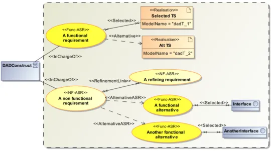
All DAD constructs must be root of an ASR tree only once in an ASR model, in order to be specified by only one implementation possibility. A sample graphical model is presented in Figure 4.
Figure 4: ASR model graphical syntax sample
5.2
Textual syntax
Like for DAD models, we created a textual editor with the Eclipse Xtext plugin. The model representation is less readable and intuitive, but contains the long descriptions of requirements. For the remaining, both representations are identical. The snippet 2 shows the same model as presented in Figure 4 written with the textual syntax.
asrmodel a s r s a m p l e { import ” dad−s a m p l e . dad ” ;
a s r 1 { 5 type : f u n c t i o n a l ; short d e s c r i p t i o n : A f u n c t i o n a l r e q u i r e m e n t ; long d e s c r i p t i o n : ”A l o n g e r d e s c r i p t i o n r e s p e c t i n g t h e l a n g u a g e g u i d e l i n e s ” ; t a r g e t : componenttype DADConstruct ; r e a l i s e d by ” dadT 1 . d a d t ” ; 10 a l t e r n a t i v e s : ” dadT 2 . d a d t ” ; } a s r 2 { type : n o n f u n c t i o n a l ; 15 short d e s c r i p t i o n : A n o n f u n c t i o n a l r e q u i r e m e n t ; long d e s c r i p t i o n : ”A l o n g e r d e s c r i p t i o n ” ; t a r g e t : componenttype DADConstruct ; } 20 a s r 2 . 1 r e f i n e s 2 { type : n o n f u n c t i o n a l ; short d e s c r i p t i o n : A r e f i n i n g r e q u i r e m e n t ; long d e s c r i p t i o n : ”A l o n g e r d e s c r i p t i o n ” ; t a r g e t : componenttype DADConstruct ; 25 } a l t e r n a t i v e g r o u p 2 . 2 r e f i n e s 2 { a s r 2 . 2 . 1 {
30 type : f u n c t i o n a l ; short d e s c r i p t i o n : A f u n c t i o n a l a l t e r n a t i v e ; long d e s c r i p t i o n : ”A l o n g e r d e s c r i p t i o n ” ; t a r g e t : componenttype DADConstruct ; r e a l i s e d by i n t e r f a c e I n t e r f a c e ; 35 } a s r 2 . 2 . 2 { type : f u n c t i o n a l ; short d e s c r i p t i o n : A n o t h e r f u n c t i o n a l a l t e r n a t i v e ; 40 long d e s c r i p t i o n : ”A l o n g e r d e s c r i p t i o n ” ; t a r g e t : componenttype DADConstruct ; r e a l i s e d by i n t e r f a c e A n o t h e r I n t e r f a c e ; } } 45 }
Listing 2: ASR model textual syntax sample
5.3
Language metamodel and concepts
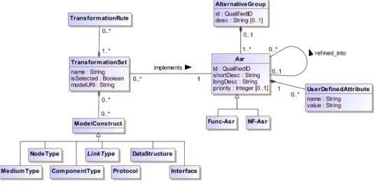
Figure 5 shows the metamodel of the ASR language. In the following, we present each language construct.
Figure 5: ASR metamodel
Asr (abstract)
An Asr represents an architecturally-significant requirement. It is identified by an id (of type QualifiedID8). It has a short identifying description and a long description expressed regarding our requirement writing guidelines. It may have a prioritisation value. An Asr must be defined as a Func-Asr or a NF-Asr. An Asr is linked to one and only one ModelConstruct that is in charge of its implementation. An Asr definition may be extended by UserDefinedAttributes.
Func-Asr
A Func-Asr is a functional architecturally-significant requirement. It may concern Services, Eventsor Exceptions. It inherits the attributes of the Asr.
NF-Asr
A NF-Asr is a non-functional architecturally-significant requirement. It may concern constraints regard-ing reliability, portability or efficiency as stated in the ISO standard [fS01]. It inherits the attributes of the Asr.
UserDefinedAttribute
In order to be able to extend, the Asrdefinition, one can create UserDefinedAttributes. It is expressed as a name-value pair.
AlternativeGroup
An AlternativeGroup is used to group multiple alternatives for the refinement of a requirement. It is identified by a qualified id and has an optional textual description. This can happen when a NF-Asr can be implemented by more than one Func-Asr. It also can happen when a Func-Asr can be implemented differently regarding other NF-Asr. For example, for a login Interface, one can decide to implement it using a secured or an unsecured connection.
ModelConstruct
A ModelConstruct refers to any DAD modelling construct that can be in charge of an Asr, i.e., a Com-ponentType, an Interface, a Protocol, a LinkType, a DataStructure, a NodeType and a MediumType.
TransformationSet
A TransformationSet is either a group of TransformationRules that are intended to weave an Asr into the DAD model, or other ModelConstruct in charge of implementing the Asr. In the latter case, the implementation of an Asr is delegated to this or these other ModelConstructs.
TransformationRule
A TransformationRule is rule that either modify the topology of a DAD model or modify attributes of a ModelConstruct. Since the transformation mechanism is still under investigation and out of this report’s scope, we do not provide more details here.
6
Requirement formalisation guidelines
With such a basic modelling language, we have to restrict the range of requirements we focus on. We need to work on requirements that already have a concrete meaning for the system architecture. We reuse here a part of the prescriptions presented in [AS02].
The requirements descriptions should be as direct as possible and use very limited vocabulary. The key words (here, mainly the architectural constructs) must be defined in a lexicon. Any requirement should focus on only one result. When hypothesises are taken into account for a requirement, they should be in the requirement description too.
For all descriptions, the architectural construct that will be responsible must be clearly identified. For all interactions, all involved resources must be clearly identifiable in the description. For func-tional requirements, the description should contain the parameters types, the return value, the possible exceptions raised and the calling type (if no result is given).
For example, a QoS requirement can be ”The Server shall respond to Client requests in max 5 seconds.” Another functional requirement example can be ”The Client requests is composed by string value. The Server returns a boolean value saying if the request has been correctly handled or not.”
7
Conclusion and future work
We exposed in this document the concepts of the IODASS method. We illustrated the problem addressed by the method and gave an overview of the three IODASS languages. We presented the graphical and textual syntaxes of the architecture languages, and detailed the language metamodel and the semantics of its concepts. Next, we did the same for the architecturally-significant requirement language and explained our requirement formalisation. Last, we illustrated our design method with a client-server architecture that we transformed in order to deal with requirement and deployment infrastructure changes.
In the future, we have to develop the transformation modelling facilities. One of the major challenge for such languages is the ability for designers to write reusable transformations in order to incrementally build a set of automated transformations for recurrent problems.
The attribute mechanism presented in Section 3.5 has to be developed. We intend to create an extensible taxonomy of attributes and let designers free to define their own attributes and associated validation rules.
We intend to investigate behavioural specification facilities to specify distant services. A set of labelled transition system-based languages exist such as Communication Sequential Processes (CSP) [Hoa85], Finite State Processes (FSP) [Mag99] and UML state machines [Obj09b]. Adding such features to services and communication protocols has a triple goal. First, it helps software engineers to have a clear understanding of the semantics of these model elements. Second, it can be used for partial validation of components composition. Third, it can be used for system animation purpose.
We plan to validate our approach with a controlled experiment on an academic problem. We will compare our method to an iterative one supported by UML models and an existing design decision traceability mechanism. We will ask students to build a component-based system from scratch and then make a couple of functional and non-functional evolutions afterwards. We will evaluate the students’ experience by questionnaires and validate the developed systems regarding to functional test cases and non-functional criteria.
References
[AS02] Ian F. Alexander and Richard Stevens. Writing Better Requirements, chapter Chap.7, pages 96–107. Addison-Wesley, 2002.
[BJPW99] Antoine Beugnard, Jean-Marc J´ez´equel, No¨el Plouzeau, and Damien Watkins. Making com-ponents contract aware. Computer, 32(7):38–45, 1999.
[CDS74] V. Cerf, Y. Dalal, and C. Sunshine. Specification of Internet Transmission Control Program. RFC 675, December 1974.
[fS01] International Organization for Standardization. Software engineering – Product quality – Part 1: Quality model. Geneva, Switzerland, 2001. ISO/IEC 9126-1:2001.
[Hoa85] Charles A. R. Hoare. Communicating Sequential Processes. Prentice-Hall, 1985.
[KR07] K. Kompella and Y. Rekhter. Virtual Private LAN Service (VPLS) Using BGP for Auto-Discovery and Signaling. RFC 4761 (Proposed Standard), January 2007. Updated by RFC 5462.
[LK07] M. Lasserre and V. Kompella. Virtual Private LAN Service (VPLS) Using Label Distribution Protocol (LDP) Signaling. RFC 4762 (Proposed Standard), January 2007.
[Mag99] Jeff Magee. Behavioral analysis of software architectures using ltsa. In 21st international conference on Software engineering (ICSE 99), pages 634–637, New York, NY, USA, 1999. ACM.
[Obj08] Object Management Group. Common Object Request Broker Architecture (CORBA) Specifi-cation, version 3.1, january 2008.
[Obj09a] Object Management Group. OMG Unified Modeling Language (OMG UML), Superstructure, version 2.2, chapter Chap.16, pages 587–605. Object Management Group, February 2009. [Obj09b] Object Management Group. OMG Unified Modeling Language (OMG UML), Superstructure,
version 2.2, chapter Chap.15, pages 525–586. Object Management Group, February 2009. [Res09] Volere Requirements Resources. The Volere Requirements Specification Template, 2009. Edition
14.
[Tel01] Telecommunications Industry Association. Commercial Building Telecommunications Cabling Standard, 2001.
A
A more complete example: a distributed image renderer
We present here a more complete illustration of the IODASS method based on an academic example. We will build a distributed and robust version of an image renderer software called PovRay9. Briefly, this freeware allows users to generate high-quality pictures from text-based description files using the ray tracing principle. Note that we only provide here the graphical models, completed by textual model parts when needed.
◦ Four ComponentTypes: a Client, a Task Dispatcher, a Worker Slave and the COTS Pov-Ray. ◦ the Worker Slave will use Pov-Ray.
◦ the Client will contact the Task Dispatcher over the internet.
◦ the Task Dispatchers and Worker Slaves will communicate over a Virtual Private Network.
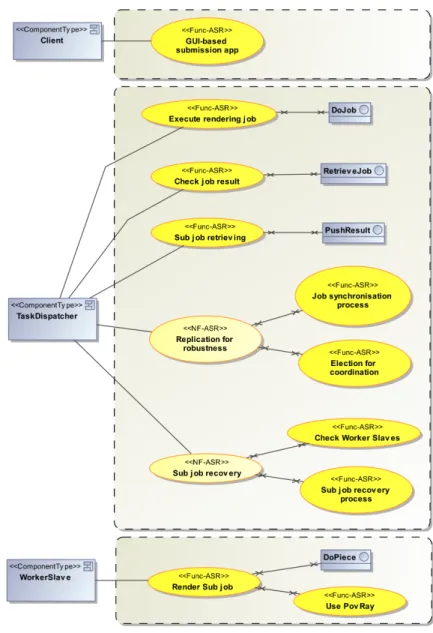
Also, we formalised the architecturally-significant functional requirements following the method guide-lines presented in Section 6. We list first the functional requirements.
1. The Client will provide a GUI-based application to allow users to submit a rendering job to Task Dispatcher.
2. The submission of a rendering job consists in a client reference, a description file (of type .pov) and an image width and height (in pixel). As an acknowledgement, the Client receive a job ID. The result of a rendering job is a .png image. The Client can disconnect after having submitted a job.
3. The Client can check periodically on the Task Dispatcher for its job results using the job ID. 4. The submission of a rendering sub-job by the Task Dispatcher to Worker Slaves contains the
same info as a job completed with the starting and ending coordinates (in pixel). The submission is asynchronous.
Then, here is the description list of the non-functional requirements. We assume here that for some non-functional requirement, we already refined them by functional requirements meant to implement the parent requirement.
1. The Task Dispatcher robustness will be implemented by the replication of the ComponentType. (a) the coordination between Task Dispatcher will be implemented by an election algorithm. (b) a synchronisation mechanism between Task Dispatcher must be implemented to replicate
submitted jobs on every Task Dispatcher.
2. Since the Worker Slave are unreliable resources, the Task Dispatcher will implement a job re-covery mechanism.
(a) a pinging mechanism must be implemented to check if a busy Worker Slave is still alive and connected.
(b) a resubmitting mechanism must be implemented by the Task Dispatcher if a Worker Slave did not send its generated image before leaving/crashing.
Figure 6: First DAD model for the Image Renderer
A.1
First models and hypothesises
The figure 6 shows the first DAD model with all identified constructs. We have the four ComponentTypes, their four related SetsOfInstances and three Nodes. The Client and Task Dispatcher are connected over the Internet, and the Task Dispatcher and the Worker Slave are in a virtual private network. As the interface with Pov-Ray is not defined yet, a usage dependency links it to the Worker Slave. This expresses an unsatisfied dependency that must be clarified by later design decisions.
For the ConnectionTypes, a set of supported protocols must be define, so the Internet ConnectorType supports TCP/IP [CDS74] and the VPN ConnectionTypes supports VPLS [KR07, LK07]. Note that we do not consider all possible protocols in order to stay simple and clear.
We define the cardinalities of the SetsOfInstances and we map them to the abstract infrastructure. We decide to deploy the Pov-Ray COTS on the same Node as the Worker Slave. For readability reason, we detail the infrastructure specifications in sub-section A.5. Nodes (resp. Media) are also typed by NodeTypes (resp. MediumTypes) where hardware-related constraints are expressed. As physical medium, we suppose that nodes are linked with CAT-5E [Tel01] cables.
Note that all model constructs are not fully detailed on the graphical representation. As examples, we show the DoJob Interface and the TCPIP protocol in Listing 3 in textual syntax. An interface can be empty. This is again used as preliminary definition of a group of services offered by a component, but where the precise specification of these services is not already defined.
dadmodel p o v 0 e x e r p t { d e f i n i t i o n { p r o t o c o l TCPIP { i s o L a y e r : ” t r a n s p o r t ” ; 5 r e l i a b l e : ” t r u e ” ; o r d e r e d : ” t r u e ” ; s e c u r e d : ” f a l s e ” ; } 10 i n t e r f a c e DoJob {
sync boolean r e n d e r I m a g e ( i n s t r i n g c l i e n t I D , i n byte [ ] f i l e , i n i n t e g e r h e i g h t , i n i n t e g e r w i d t h ) ;
accepts TCPIP ; }
}
15 }
Listing 3: Exerpt of the first DAD model in textual syntax
The Figure 7 shows the first ASR model summarising the requirements and their targets.
Figure 7: First ASR model for the Image Renderer
A.2
A simple requirement implementation
We will select a requirement and either refine it or create a set of transformations rules that weave the requirement into the architecture model. Let’s say that we decide to first look at the Check Worker Slaves requirement. We decide to create a CheckWorker Interface that must be implemented by the Worker Slaves. The communication will be supported by the same ConnectorType. Figure 8 shows the modified part from the model given in Figure 7. Figure 9 illustrate the new dependency created by the new interface.
A.3
Functional alternatives of the Job Synchronisation requirement
For a couple of requirements, a list of alternatives can be represented in the ASR model. Figure 10 illustrates the functional alternatives for the job synchronisation requirement with their corresponding implementing interfaces.
Figure 8: ASR model exerpt with the CheckWorker Interface
Figure 9: Corresponding new DAD exerpt
Figure 10: Functional alternatives for job synchronisation
A.4
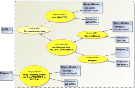
Implementation possibilities of the DoJob interface
For each interface, a set of non-functional requirements can alter the functional semantics. Like Com-ponentTypes, Interfaces can be the root elements of a decision tree. Let’s say that we may want to perform the operations offered by the DoJob interface on a secured or unsecured connection. We can now specify more precisely the DoJob Interface with new operations (connect()) and the accepted protocols that satisfy the requirements. In Figure 11, we selected the secured connection alternative.
The DAD model has to be updated too. The LinkType between the Client and the Task Dispatcher must now support the RPC Protocol.
A.5
Infrastructure constraints implementation
Infrastructure constraints can influence the final design of an architecture. When such constraints are taken into account lately in the system design, this can result in incompatibilities between the software and the supporting hardware.
Also, as highlighted in Peter Deutsch’s eight fallacies of distributed computing, the network topology can be subject to changes during the software lifetime. Let’s suppose that the connection between the Client and the Task Dispatcher goes through a firewall. This firewall has strict routing rules and does
Figure 11: DoJob implementation
not allow RPC communication. The new deployment part of the modified DAD model is presented in Figure 12. We only introduce here the firewall Node in the middle of the communication between the Client and the Task Dispatcher. No resolution about the new constraints is taken into account at this point.
Figure 12: DAD deployment exerpt with the firewall
As explained in Section 4, a Medium is also constrained by a set of accepted or rejected Protocols. The firewall is represented as a Node that can restrict the Protocols accepted by the Media linked to it. It does not host any SetOfInstances since no part of the architecture must be deployed on it. A new MediumType (CAT-5E-NoRPC) must be introduced to link the firewall to the cNode. We reject all RPC-based protocols for this new MediumType (remember that we have inheritance for Protocols). The instantiated Medium has to host the rpc Connectors, so that the incompatibility is clearly showed on the model. We also introduce a Site in order to geographically group the firewall and the tdNode for readability and documentation purposes. Note that the accepted and rejected protocols are not represented in the graphical model for readability reasons.
All these constraints and decisions must be reflected in the ASR model. The Figure 13 illustrate these modifications. Since we already decided to use a secured connection, we only show the decisions for that alternative. Also, we only provide the model for the DoJob Interface. The same reasoning
applies to the other Interface offered to the Client.
In order integrate the new constraint in the architecture, we identified two alternatives: (i) modify the Task Dispatcher implemented Interface and use another Protocol; (ii) use a wrapper that handles requests from Clients and forward them to the Task Dispatcher. We decide to go for the second solution, so we create a new ComponentType in charge of wrapping the requests from one Protocol to another.
Figure 13: Communication protocol constraints for the DoJob Interface
The Figure 14 shows the modified part of the architecture model.
B
DAD grammar
grammar be . f u n d p . i n f o . i o d a s s . t e x t u a l . a r c h i . Dad w i t h o r g . e c l i p s e . x t e x t . common . T e r m i n a l s
g e n e r a t e dad ” h t t p : / /www. f u n d p . be / i n f o / i o d a s s / t e x t u a l / a r c h i /Dad” 5 DADModel : ’ dadmodel ’ dadname=ID ’ { ’ ( i m p o r t s += I m p o r t ) ∗ d e f = D e f i n i t i o n ? a s s = A s s e m b l a g e ? 10 dep = Deployment ? ’ } ’ ; I m p o r t : ’ i m p o r t ’ importURI=STRING ’ ; ’ ; 15 M o d e l C o n s t r u c t :
’ componenttype ’ compT=[ ComponentType |FQN] | ’ d a t a t y p e ’ d t =[ D a t a t y p e |FQN] | ’ i n t e r f a c e ’ i f a c e =[ I n t e r f a c e |FQN] | ’ l i n k t y p e ’ l k t y p e =[ LinkType |FQN] | ’ p r o t o c o l ’ p r o t o =[ P r o t o c o l |FQN ] ; FQN : 20 ID ( ’ . ’ ID ) ∗ ; P r o p e r t y : name=ID ’ : ’ v a l u e=STRING ’ ; ’ ; 25 // // 1 . D e f i n i t i o n // D e f i n i t i o n : 30 ’ d e f i n i t i o n ’ ’ { ’ ( d t s += D a t a t y p e | i n t e r f a c e s+=I n t e r f a c e | c t s += ComponentType | p r o t o s += P r o t o c o l | l i n k s += LinkType | i n n e r C o n f i g s += I n n e r C o n f i g | i n n e r D e p s += I n n e r D e p e n d e n c y ) ∗ ’ } ’ ; 35 // custom & p r i m i t i v e s t y p e s G e n e r i c T y p e : ( p t=P r i m i t i v e T y p e | c t =[ ComplexType ] ) ( many ? = ’ [ ] ’ ) ? ; 40 ComplexType : D a t a t y p e | I n t e r f a c e ; D a t a t y p e : { Datatype } ’ d a t a t y p e ’ name=ID ’ { ’ 45 ( r e c s += Record ) ∗ ’ } ’ ; Record : t y p e=G e n e r i c T y p e name=ID ’ ; ’ ; 50 P r i m i t i v e T y p e : name =( ’ i n t e g e r ’ | ’ c h a r ’ | ’ s t r i n g ’ | ’ byte ’ | ’ b o o l e a n ’ | ’ f l o a t ’ ) ; // i n t e r f a c e s 55 I n t e r f a c e : { I n t e r f a c e } ’ i n t e r f a c e ’ name=ID ’ { ’ s e r v i c e s += S e r v i c e ∗ ( ’ a c c e p t s ’ i n P r o t o c o l L i s t=P r o t o c o l L i s t ’ ; ’ ) ? 60 ’ } ’ ; S e r v i c e : O p e r a t i o n | Event | E x c e p t i o n ; 65 O p e r a t i o n : S y n c O p e r a t i o n | A s y n c O p e r a t i o n ; S y n c O p e r a t i o n : { S y n c O p e r a t i o n }
’ s y n c ’ ( r e s u l t T y p e=G e n e r i c T y p e ) ? name=ID ’ ( ’ ( sOpArgs=OpArgList ) ? ’ ) ’ ( ’ r a i s e s ’ e x s= E x c e p t i o n L i s t ) ? ’ ; ’ ;
70
A s y n c O p e r a t i o n : { A s y n c O p e r a t i o n }
OpArgList :
75 o p A r g l i s t+=OpArgument ( ’ , ’ o p A r g l i s t+=OpArgument ) ∗ ;
OpArgument :
a c c e s s=OpAccess a r g t y p e=G e n e r i c T y p e name=ID ;
80 enum OpAccess : i n =’ i n ’ | o u t =’ out ’ | i n o u t =’ i n o u t ’ ; Event : { Event } ’ e v e n t ’ name=ID ’ ( ’ ( e v A r g s=A r g L i s t ) ? ’ ) ’ ’ ; ’ ; 85 E x c e p t i o n : { E x c e p t i o n } ’ e x c e p t i o n ’ name=ID ’ ( ’ ( a r g s=A r g L i s t ) ? ’ ) ’ ’ ; ’ ; E x c e p t i o n L i s t : 90 e x l i s t +=[ E x c e p t i o n | FQN] ( ’ , ’ e x l i s t +=[ E x c e p t i o n | FQN ] ) ∗ ; A r g L i s t : a r g l i s t+=Argument ( ’ , ’ a r g l i s t+=Argument ) ∗ ; 95 Argument : a r g t y p e=G e n e r i c T y p e name=ID ; // c o m p o n e n t t y p e s 100 ComponentType : {ComponentType}
’ componenttype ’ name=ID ( ’ e x t e n d s ’ e x t e n d s =[ ComponentType |FQN ] ) ? ’ { ’
( i n n e r C T s += ComponentType | i n n e r I n t e r f a c e s += I n t e r f a c e | f a c e t s += F a c e t | i n n e r D e l s += I n n e r D e l e g a t i o n | i n n e r C o n f i g s += I n n e r C o n f i g | i n n e r D e p s += I n n e r D e p e n d e n c y ) ∗ ( p r o p L i s t = P r o p e r t y L i s t ) ? 105 ’ } ’ ; F a c e t : usedType=FacetUsedType f a c e t L i s t +=[ I n t e r f a c e |FQN] ( ’ , ’ f a c e t L i s t +=[ I n t e r f a c e |FQN ] ) ∗ ’ ; ’ ; 110 enum FacetUsedType : i m p l e m e n t s =’ i m p l e m e n t s ’ | u s e s =’ u s e s ’ ; I n n e r C o n f i g :
’ c o n n e c t ’ ctFrom =[ ComponentType |FQN] ’ : : ’ r e q F a c e t =[ I n t e r f a c e ] ’ to ’ ctTo =[ ComponentType |FQN] ’ : : ’ p r o v F a c e t =[ I n t e r f a c e ] ’ with ’ conType =[ ConnectorType ] ’ ; ’ ;
115
I n n e r D e p e n d e n c y :
usingCT =[ ComponentType |FQN] ’ u s e s ’ usedCT =[ ComponentType |FQN] ’ ; ’ ;
I n n e r D e l e g a t i o n :
120 ’ d e l e g a t e ’ usedType=FacetUsedType f a c e t =[ I n t e r f a c e |FQN] ’ to ’ c t =[ ComponentType |FQN] ’ with ’ d e l T y p e =[ D e l e g a t e T y p e ] ’ ; ’ ; // p r o t o c o l s P r o t o c o l : 125 ’ p r o t o c o l ’ name=ID ( ’ e x t e n d s ’ e x t e n d s =[ P r o t o c o l ] ) ? ’ { ’ ( p r o p s += P r o p e r t y ) ∗ ’ } ’ ; P r o t o c o l L i s t : 130 p r o t o c o l s +=[ P r o t o c o l ] ( ’ , ’ p r o t o c o l s +=[ P r o t o c o l ] ) ∗ ; // l i n k t y p e s LinkType : 135 ConnectorType | D e l e g a t e T y p e ; ConnectorType : ’ c o n n e c t o r t y p e ’ name=ID ’ { ’ ’ a c c e p t s ’ c o n P r o t o c o l L i s t=P r o t o c o l L i s t ’ ; ’ 140 ’ mode ’ conMode=ConnectionMode ’ ; ’ p r o p s += P r o p e r t y ∗ ’ } ’ ; D e l e g a t e T y p e : 145 ’ d e l e g a t e t y p e ’ name=ID ’ { ’ ’ a c c e p t s ’ p r o t o c o l L i s t=P r o t o c o l L i s t ’ ; ’ ’ mode ’ delMode=D e l e g a t i o n M o d e ’ ; ’
p r o p s += P r o p e r t y ∗ ’ } ’ ; 150 enum ConnectionMode : o n e 2 o n e =’ o ne 2 on e ’ | one2many=’one2many ’ | many2many=’many2many ’ ; enum D e l e g a t i o n M o d e : 155 s i m p l e =’ s i m p l e ’ | random=’random ’ | r o u n d r o b i n =’ r o u n d r o b i n ’ | b r o a d c a s t =’ b r o a d c a s t ’ | l o a d B a l a n c i n g =’ l o a d B a l a n c i n g ’ ; // p r o p e r t i e s P r o p e r t y L i s t : { P r o p e r t y L i s t } 160 ’ p r o p e r t y l i s t ’ ’ { ’ ( p r o p s += P r o p e r t y ) ∗ ’ } ’ ; // 165 // 2 . A s s e m b l a g e // A s s e m b l a g e : ’ a s s e m b l a g e ’ ’ { ’ 170 ( s o i s += S o I | c o n n e c t o r s += C o n n e c t o r | d e l e g a t e s += D e l e g a t e ) ∗ ( c o n n e c t i o n s += C o n n e c t i o n | d e p e n d e n c i e s += Dependency ) ∗ ’ } ’ ; S o I :
175 ’ s o i ’ name=ID ’ [ ’ m i n c a r d=INT maxcard=INT ’ ] ’ ’ : ’ compT=[ ComponentType |FQN] ( p r o p L i s t = P r o p e r t y L i s t ) ? ’ ; ’ ;
C o n n e c t o r :
’ c o n n e c t o r ’ name=ID ( ’ [ ’ s i z e =INT ’ ] ’ ) ? ’ : ’ conT =[ ConnectorType ] ( ’ p r o t o c o l ’ p r o t o c o l =[ P r o t o c o l |FQN ] ) ? ( p r o p L i s t = P r o p e r t y L i s t ) ? ’ ; ’ ;
180 D e l e g a t e :
’ d e l e g a t e ’ name=ID ( ’ [ ’ s i z e =INT ’ ] ’ ) ? ’ : ’ d e l T =[ D e l e g a t e T y p e ] ( p r o p L i s t = P r o p e r t y L i s t ) ? ’ ; ’ ;
C o n n e c t i o n :
’ c o n n e c t ’ s o i F r o m =[ S o I ] ’ : : ’ r e q F a c e t =[ I n t e r f a c e |FQN] ’ to ’ s o i T o =[ S o I ] ’ : : ’ p r o v F a c e t =[ I n t e r f a c e |FQN] ’ with ’ con =[ C o n n e c t o r ] ( ’ [ ’ c k i d=INT ’ ] ’ ) ? ( ’ t h r o u g h ’ d e l e g a t e =[ D e l e g a t e ]
( ’ [ ’ d e l i d=INT ’ ] ’ ) ? ) ? ’ ; ’ ; 185 Dependency : { Dependency } u s i n g S o I =[ S o I ] ’ u s e s ’ u s e d S o I =[ S o I ] ’ ; ’ ; // 190 // 3 . Deployment // Deployment : { Deployment } ’ deployment ’ ’ { ’
195 ( s i t e s += S i t e | n o d e s += Node | media += Medium ) ∗ d e c l a r e S t a t e m e n t s += D e c l a r e H a r d w a r e ∗ d e p l o y S t a t e m e n t s += D e p l o y S t a t e m e n t ∗ ’ } ’ ; 200 S i t e : ’ s i t e ’ name=ID ’ { ’ p r o p e r t i e s += P r o p e r t y+ ’ } ’ ; 205 Node :
’ node ’ name=ID ( ’ e x t e n d s ’ e x t e n d s =[ Node ] ) ? ’ { ’ p r o p e r t i e s += P r o p e r t y+ ’ } ’ ; 210 Medium : ’ medium ’ name=ID ’ { ’ p r o p e r t i e s += P r o p e r t y+ ’ } ’ ; 215 D e c l a r e H a r d w a r e :
’ d e c l a r e ’ name=ID ( ’ [ ’ s i z e =INT ’ ] ’ ) ? ’ : ’ h a r d w a r e =[ Hardware ] ’ ; ’ ;
Hardware : Node | Medium ;
D e p l o y S t a t e m e n t :
’ d e p l o y ’ e l e m e n t =[ ElementToDeploy ] ’ on ’ p h y s i c a l E l e m =[ D e c l a r e H a r d w a r e ] ( ’ [ ’ INT ’ ] ’ ) ? ’ ; ’ ;
ElementToDeploy :
C
ASR grammar
grammar be . f u n d p . i n f o . i o d a s s . t e x t u a l . a s r . Asr w i t h be . f u n d p . i n f o . i o d a s s . t e x t u a l . a r c h i . Dad
i m p o r t ” h t t p : / /www. f u n d p . be / i n f o / i o d a s s / t e x t u a l / a r c h i /Dad” a s dad i m p o r t ” h t t p : / /www. e c l i p s e . o r g / emf / 2 0 0 2 / E c o r e ” a s e c o r e 5 g e n e r a t e a s r ” h t t p : / /www. f u n d p . be / i n f o / i o d a s s / t e x t u a l / a s r / Asr ” ASRModel : ’ a s r m o d e l ’ a s r m o d e l=ID ’ { ’ 10 i m p o r t s+= I m p o r t a s r += (ASR | A S R A l t e r n a t i v e s ) ∗ ’ } ’ ; A S R A l t e r n a t i v e s : 15 ’ a l t e r n a t i v e g r o u p ’ grpname=ASRID ( ’ r e f i n e s ’ p a r e n t A s r=ASRIDRef ) ? ’ { ’ ( ’ d e s c r i p t i o n : ’ d e s c r=STRING ’ ; ’ ) ? a s r += ASR∗ ’ } ’ ; 20 ASR : ’ a s r ’ name=ASRID ( ( ’ r e f i n e s ’ p a r e n t A s r=ASRIDRef ) | ( s e l e c t e d ?= ’ i s s e l e c t e d ’ ) ) ? ’ { ’ ’ t y p e : ’ t y p e =( ’ f u n c t i o n a l ’ | ’ n o n f u n c t i o n a l ’ ) ’ ; ’ ’ s h o r t d e s c r i p t i o n : ’ s h o r t D e s c=ID ’ ; ’ ’ l o n g d e s c r i p t i o n : ’ l o n g D e s c=STRING ’ ; ’ 25 ’ t a r g e t : ’ t a r g e t=M o d e l C o n s t r u c t ’ ; ’ ( ’ r e a l i s e d by ’ ( importURI=STRING | p r i m i t i v e=M o d e l C o n s t r u c t ) ’ ; ’ ) ? ( ’ a l t e r n a t i v e s : ’ a l t e r n a t i v e s+= A l t e r n a t i v e ( ’ , ’ a l t e r n a t i v e s+=A l t e r n a t i v e ) ∗ ’ ; ’ ) ? ’ } ’ ; 30 A l t e r n a t i v e : importURI=STRING | a l t P r i m i t i v e=M o d e l C o n s t r u c t ; ASRIDRef : a s r I D =[ASR | ASRID ] ; 35 ASRID r e t u r n s e c o r e : : E S t r i n g : INT ( ’ . ’ INT ) ∗ ;