RESEARCH OUTPUTS / RÉSULTATS DE RECHERCHE
Author(s) - Auteur(s) :
Publication date - Date de publication :
Permanent link - Permalien :
Rights / License - Licence de droit d’auteur :
Institutional Repository - Research Portal
Dépôt Institutionnel - Portail de la Recherche
researchportal.unamur.be
University of Namur
Deriving Configuration Interfaces from Feature Models : A Vision Paper
Boucher, Quentin; Perrouin, Gilles; Heymans, Patrick
Published in:
Proceedings of the Sixth International Workshop on Variability Modelling of Software-intensive Systems
(VaMoS'12), Leipzig, Germany, January 25-27,
Publication date:
2012
Document Version
Early version, also known as pre-print
Link to publication
Citation for pulished version (HARVARD):
Boucher, Q, Perrouin, G & Heymans, P 2012, Deriving Configuration Interfaces from Feature Models : A Vision
Paper. in Proceedings of the Sixth International Workshop on Variability Modelling of Software-intensive
Systems (VaMoS'12), Leipzig, Germany, January 25-27,. pp. 37-44.
General rights
Copyright and moral rights for the publications made accessible in the public portal are retained by the authors and/or other copyright owners and it is a condition of accessing publications that users recognise and abide by the legal requirements associated with these rights. • Users may download and print one copy of any publication from the public portal for the purpose of private study or research. • You may not further distribute the material or use it for any profit-making activity or commercial gain
• You may freely distribute the URL identifying the publication in the public portal ?
Take down policy
If you believe that this document breaches copyright please contact us providing details, and we will remove access to the work immediately and investigate your claim.
Deriving Configuration Interfaces from Feature Models :
A Vision Paper
Quentin Boucher, Gilles Perrouin
PReCISE Research Centre Faculty of Computer Science University of Namur, Belgium
{qbo,gpe}@info.fundp.ac.be
Patrick Heymans
PReCISE Research Centre Faculty of Computer Science University of Namur, Belgium
INRIA Lille-Nord Europe
Université Lille 1 – LIFL – CNRS , France
[email protected]
ABSTRACT
In software product lines, feature models are the de-facto standard for representing variability as well as for configur-ing products. Yet, configuration relyconfigur-ing on feature models faces two issues: i) it assumes knowledge of the underly-ing formalism, which may not be true for end users and ii) it does not take advantage of advanced user-interface controls, leading to usability and integration problems with other parts of the user interface. To address these issues, our research focuses on the generation of configuration inter-faces based on variability models, both from the visual and behavioral perspectives. We tackle visual issues by gener-ating abstract user-interfaces from feature models. Regard-ing configuration behavior, in particular the configuration sequence, we plan to use feature configuration workflows, variability-aware models that exhibit similar characteristics as of task, user, discourse and business models found in the in the human-computer interaction community. This pa-per discusses the main challenges and possible solutions to realize our vision.
Keywords
Software Product Lines, Feature Configuration Workflows, Configuration Interfaces
1.
INTRODUCTION
Along with the development of e-commerce, mass cus-tomization [29] which was formerly performed by software engineers is now realized by product customers through an adequate configuration interface. These configuration ap-plications have permeated a number of markets such as car manufacturers, clothing or computer hardware. Software products are also configurable, service-based applications being one of the most well-known example. The software product line (SPL) community has addressed the design of such configurators [7] by relying on feature models (FMs).
Permission to make digital or hard copies of all or part of this work for personal or classroom use is granted without fee provided that copies are not made or distributed for profit or commercial advantage and that copies bear this notice and the full citation on the first page. To copy otherwise, to republish, to post on servers or to redistribute to lists, requires prior specific permission and/or a fee.
VaMoS’12, January 25-27, 2012 Leipzig, Germany Copyright 2012 ACM 978-1-4503-1058-1 ...$10.00.
Indeed, selecting options of a particular product within a given configurator amounts to perform interactive configu-ration of a feature model where features correspond to op-tions and decisions propagated throughout the configuration interface enabling or disabling specific options according to constraints.
Therefore, several SPL tools such as SPLOT [30] or Pure:-:Variants [6] offer configuration facilities based on visual resentations of FMs, mostly adopting a “tree-based” rep-resentation of the features’ hierarchy. However, there are many ways to graphically represent FMs [35, 14] and these ways should be tailored to the usage needs. For example, a preliminary survey [23] has questioned the suitability of the FODA-like notation for editing FMs in practice, resulting in the definition of a textual feature modelling language [8, 10] targeted at SPL engineers and developers. Industrial feed-back was promising [21]. Additional evidence is provided by Pleuss et al. [35] while comparing different graphical repre-sentations of FMs; tailoring the reprerepre-sentations to the task is an important aspect. In this paper, we focus on the config-uration needs of end users who will configure their products through an appropriate interface. Thus, it is interesting to look at the human-computer interaction community to fur-ther investigate the problem. Configuration interfaces can be thought as plastic user interfaces [45], which adapt them-selves due to interactive configuration and can be deployed on a variety of devices. Therefore, for configuration pur-poses, plasticity may involve omitting the feature hierarchy or break it into smaller parts [24] either to support a delib-erate design or to accommodate hardware constraints. This hence discards configurators that are too rigid with respect to the FM’s hierarchy representation. There are also lessons to be learned from the database community, where the gen-eration of form-based interfaces has been addressed [26].
As a result, our vision combines ideas coming from model-based and data-model-based graphical user interfaces (GUIs) gen-eration with our previous research feature-based configura-tion [25, 22]. We sketch in this paper the main elements of this vision as well as related research challenges.
The paper is organized as follows. Section 2 sketches our model-based vision for configuration interfaces gener-ation, illustrated through examples. Research challenges to be solved to realize this vision are discussed in Section 3. Related work is surveyed in Section 4. Finally, Section 5 wraps up the paper and presents some on-going and future developments.
Feature Model Concrete User Interface Abstract User Interface Feature Configuration Workflows Views Property Sheet
Figure 1: Interface Generation Process
2.
APPROACH OVERVIEW
As we mentioned above, direct configuration from the FM may not suit every user need. Therefore, our vision is based on the decoupling of the FM and the configuration user in-terface (UI) by combining separation of concerns [43] and generative techniques [39]. The base process is sketched in Figure 1.
Our approach relies on the notion of Abstract User Inter-face (AUI) [9]. According to Coutaz et al. [9], an AUI is “a canonical expression of the rendering of the domain concepts and functions in a way that is independent of the interac-tors available on the targets”. In other words, an AUI is a language and target platform independent description of the UI, which allows considering mappings from the feature model, configuration process and its interaction with the UI in an unique and reusable manner. This AUI can be directly generated from the FM with the possibility to use Views [24] or Feature Configuration Workflows [22] to tweak configu-ration interface decomposition and sequencing logic. The layout of the elements composing the UI can be guided by a Property sheet containing beautifying information. Once created, the AUI can be then transformed in a Concrete User Interface (CUI). CUI’s look and feel could also be driven by information contained in the Property sheet. Depending on the required sophistication level of the interface, different combinations of views, configuration workflows and prop-erty sheets are envisioned, as explained in the subsequent paragraphs.
Thus, this architecture exhibits the following benefits: • Seamless integration with existing approaches.
The explicit distinction between variability and inter-face modelling aspects ease the connection of the ap-proach with state of the art research. For example, at the feature modelling level, we can take advantage of modularity techniques [1, 25, 24, 3] but also automated analyses [5, 30]. Regarding interfaces, the approach can be integrated with existing frameworks and CUI generation tools [9].
• Inconsistent configuration analysis and evolu-tion. Since the configuration logic is not implemented directly in the CUI, it is easy to use the analysis tools above to detect conflicting situations. Also, evolution is managed at the abstract level and can be enacted via reapplication of the process.
• Platform Independence With the development of different devices, it is not rare that the same con-figuration interface needs to be deployed on various computing environments (OS, Screen, etc). Thanks to its MDA-like architecture [46], we can reuse con-figuration logic across languages and platforms. Some parts of the framework can be made even more generic, if we devise transformation patterns such as the ones sketched in [39].
In the following, we detail how the various models can be employed for the generation of UIs of growing complexity.
2.1
Form-like Interfaces
Forms “are a structured means of displaying and collecting information for further processing” [38]. They have become a natural part of a wide variety of applications and websites. In the database domain, generating forms from data models is a common task. There, forms to query or insert informa-tion into a database are generated from data models, using their meta-data for example [20]. FMs being interpreted as class models with a containment hierarchy [15], a similar approach could be applied in SPL engineering.
Forms are the simplest kind of configuration interfaces tar-geted by our approach. Thus, using only an FM one would be able to generate a basic form. To make this transforma-tion possible, a set of rules for mapping FM constructs to UI widgets is required. For example, TVL bool attributes could be translated to checkboxes, enum attributes to drop-down lists or list boxes, depending on the numbers of available val-ues, etc. Even if this translation is technically feasible, the result would be rough as it is relies only on information con-tained in TVL models (and FMs in general) which is rather technical. For example, using feature and attribute names
as label for the input fields might not be expressive enough to understand their meaning. To tackle this problem we propose to add a so-called Property Sheet. This document is meant to store display information to beautify the UI, by attaching a display name, help text, etc. to features and attributes.
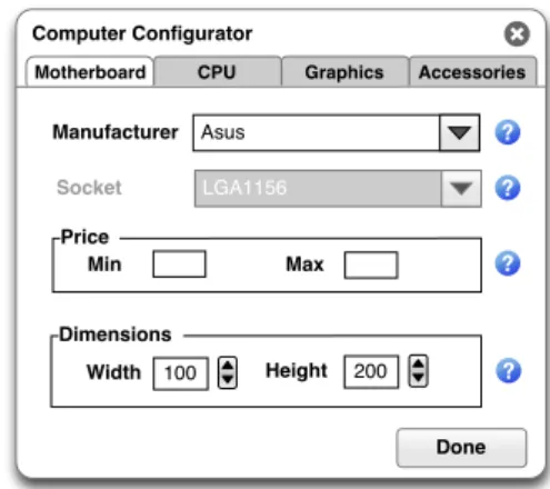
Based on the FM and the associated Property sheet, an AUI can be defined for the form. AUI languages describe UIs in terms of Abstract Interaction Objects (AIOs). Those AIOs present the advantage of being independent of any platform and any modality of interaction (graphical, vocal, virtual reality and so on). In this way, we keep our approach as generic as possible. This AUI will finally be translated into a CUI which is the implementation of the UI in a given lan-guage for a specific platform. For example, Figure 2 sketches a concrete UI corresponding to a form for the following TVL model representing the variability of a motherboard: ro ot M o t h e r b o a r d { g r o u p o n e O f { As us { i fIn : p a r e n t . s o c k e t == L G A 1 1 5 6 ;} , A o p e n { i fIn : p a r e n t . s o c k e t == ASB 1 ;} } en um s o c k e t in { LGA1156 , AS B1 }; int p r i c e in [ 0 . . 5 0 0 ] ; s t r u c t d i m e n s i o n { int h e i g h t ; int w i d t h ; } }
There, labels for the different input fields, like Manufac-turer, come from the Property sheet. Feature decomposition and enumerated attributes both have been represented using drop-down lists. Integers have been implemented in two dif-ferent manners: the dimension structure and its width and height attributes with a stepper field, and the price with two fields associated to Min and Max values. Such a repre-sentation of the price attribute has to be defined using the Property sheet. One can also notice that the Socket option is greyed as the choice of this attribute has been determined by the Manufacturer selection. Integration of the UI with solvers will be discussed in Section 3. Question marks on the right side of the input fields correspond to help information. This information has to be defined in the Property sheet.
Computer Configurator Socket Done Manufacturer Asus LGA1156 Price Min Max Dimensions 100 Width Height 200
Figure 2: Sketch of a Form UI
2.2
View-based Interfaces
Forms are suitable for relatively small FMs but once their size increases, managing all the variability in a single form becomes a non trivial task. The user might be overwhelmed by all this information displayed in a single monolithic screen. To manage this complexity, we propose to divide FMs de-pending on the different concerns they include using multi-view FMs [25].
A view is “a simplified representation of an FM that has been tailored for a specific stakeholder, role, task, or, to generalize, a particular combination of these elements which we call a concern” [25] and corresponds to a subset of the features of the FM. Several views allow to divide the FM into smaller, more manageable parts.
Computer Configurator Socket Done Manufacturer Asus LGA1156 Price Min Max Dimensions 100 Width Height 200 Accessories Graphics CPU Motherboard
Figure 3: Sketch of a View-based UI
Developers now have to define Views corresponding to the FM (see Figure 1). Hubaux et al. identified two ways of defining views: through extensional definitions, i.e. by enumerating all features appearing in a view, or through in-tentional definitions, i.e. by providing a language that takes advantage of the tree structure and avoids lengthy enumer-ations [25]. Once views have been defined, views-related beautifying information similar to FM-related one can be defined in the Property sheet. It is meant to beautify the UI with views-related information like their display name, their display order, etc.
The illustrative TVL model of previous section restricted the configuration of a computer to its motherboard. But in actual configuration, other concerns like CPU, graphics or accessories could also be included in the FM. To avoid displaying all the information in the same window one could define four views corresponding to the different concerns of a computer configuration. Figure 3 sketches an interface illus-trating this separation of concern. There, the different views have been implemented by four tabs but one could think about different implementation approaches which could be influenced by information contained in the Property sheet.
2.3
Workflow-based Interfaces
Views might not be sufficient in some cases where more complex constructs like ordered or user-determined sequences of views are required. We identified two distinct families of UIs belonging to this category: wizards and eclipse-like applications. A wizard is a UI where the user is guided through a succession of screens, eventually influenced by her
T1 T21 T22 T4 T32 T31 T33 C1 Legend Start condition End condition
Condition XOR split XOR join
No
Yes T5 T34
Figure 4: Illustrative YAWL workflow of a complex UI
choices. This kind of UI is generally used at compilation time. Eclipse-like interfaces are UIs where the user deter-mines her task ordering by selecting the different options available in the interface (toolbar, menubar, etc.). Contrar-ily to wizards, this kind of UI is generally used to manage configuration at runtime.
To describe the behaviour of those high-level UIs, we sug-gest to use Feature Configuration Workflows (FCWs) pro-posed by Hubaux et al. [22]. There, the authors extend their work on views by proposing to use workflows to drive their configuration. Their research was inspired by the concept of multi-level staged configuration of Czarnecki et al. [13]. The workflow defines the configuration process and each view on the FM is assigned to a task in the workflow. A view is con-figured when the corresponding workflow task is executed. An FCW is thus a combination of views on the FM, workflow and the mapping between them. Up to now, FCWs focused on distributed configuration among several stakeholders but one might easily adapt it to other purposes like the dynamic behaviour of a UI in our case.
While the link between wizards and FCWs is direct (a wiz-ard is a predefined sequence of screens where user’s choices will determine the path between a start and an end), it re-quires more explanation for eclipse-like UIs. Even if the use of such complex UIs seems non-linear, we claim it can still be represented using workflows. Figure 4 is an example of such workflow expressed in the YAWL formalism [44]. There, T* labels correspond to tasks and C1 label refers to a condition. Our complex UI is composed of a home screen (T1) where the user has three options (T21, T31, T4). Once she has cho-sen one, she enters a “sub-workflow” which can be composed of a single task (T4) , a sequence of tasks (T21-T22) or more complex (T31, T32, T33, T34). Once tasks of the selected path are complete, task T5 is reached. It corresponds to a “dummy” join task. Then comes condition C1 which is used to determine if the configuration is finished. If the condition is not satisfied, the workflow goes back to task T1, so creat-ing a loop. On the other side, a positive answer would mean that the configuration is finished. This condition could ei-ther be automatic (the workflow loops until ei-there is no more variability to be configured) or manual (the user clicks on a button to indicate that she has completed her configuration task).
After having defined views, the workflow representing the dynamic aspect of the UI thus has to be modelled and its
tasks attached to the different views to create a so-called FCW. FCW-related beautifying information can also be stored in the Property sheet along with information related to the FM and views.
3.
CHALLENGES
As previously mentioned, Section 2 is an overview of the proposed approach to be implemented. In this section, we will discuss some of the remaining challenges and leads to explore.
User Interface Description Language.
Different languages, so called User Interface Description Languages (UIDLs), have been proposed in the literature to express AUIs. They consist of languages which describe various aspects of an UI in an abstract manner, like e.g. AIOs. UsiXML [46], UIML [2] or XUL [49] are some examples of such languages. Each UIDL has its own characteristics like supported plat-forms, target languages, device-independence or available tools. Guerrero-Garc´ıa and Gonz´alez-Calleros [19], and Sou-chon and Vanderdonckt [41] surveyed some of those lan-guages based on their criteria. We will also have to con-duct a similar survey to select the most appropriate UIDL according to our own requirements.AIO mapping.
Once the UIDL has been selected, a map-ping between FM constructs and AIOs will have to be de-fined. It includes low-level as well as “pattern” mappings. By low-level we mean direct mappings between FM con-structs and AIOs like checkboxes for Boolean attributes, for example. Most mappings will not be to-one but one-to-many based either on properties of the FM constructs or on user preferences. An enumerated attribute can, for ex-ample, be represented either by a list box or a drop-down list, depending on the number of elements in the enumera-tion. Additionally, some patterns in FMs might also be as-sociated to specific AIOs. For example, an or -decomposed feature whose sub-features are leaf nodes could be mapped to a list box allowing selection of multiple values. For this task, we can rely on guidelines commonly accepted in the human-computer interaction (HCI) community [48].Objects placement.
Another aspect which we will have to take into consideration is the placement of the identified AIOs on the screen. Following the HCI literature, this task is non-trivial and there have been successes in limited do-mains such as dialogue box design and remote controls [32]. An alternative solution would be to provide the UI designer with a set of automatically generated atomic AIOs which she can place in the layout structure she has defined, so en-suring the clarity of the layout. Schramm et al., for example, implemented this second option [40].Property sheet.
A language influencing the beautification of the UI will have to be defined. Our first intention is to extend TVL with some UI-specific tags. We have to evalu-ate the feasibility of this approach, especially the integration of TVL annotations with views and FCWs. Thanks to the structuring mechanism of TVL (include construct), beautify-ing annotations could be defined either in the same file as the FM or in a specific file, so not interfering with the read-ing of the FM. Supported tags should at least include label(the label of an UI element), group (to define a group of features logically linked), group element (to attach a feature to a group), ordering (to define the order of the features), hide (to not display a feature in the UI) and default (to de-fine the default value in the UI) constructs. View definition instructions could also be part of those constructs.
Views.
In their research on views, Hubaux et al. focused on three main aspects: view specification, view coverage and view visualisation [25]. There are two ways of specifying views: extensional definition (enumerate each feature ap-pearing in a view) and intentional definition (take advan-tage of the tree structure) using a subset of XPath1. In our case, we could implement the extensional definition us-ing TVL tags, as mentioned in previous challenge. A drag-and-drop tool is another solution which could be explored. The second aspect, view coverage, should also be verified for UIs as it guarantees that all configuration questions be eventually answered. The conditions defined by the authors should be sufficient for our UI generation approach and re-quire no modification. Finally, the three view visualisations presented in [25], such as displaying only features that are relevant for the view are of little interest in UI generation. However, we might go through the same process to identify different ways of displaying views in a UI (tabs, etc.).Feature Configuration Workflows.
As previously mention-ed, an FCW is a workflow such that tasks are associated to FM-views. A view will have to be configured during the execution of its associated task [22]. Thanks to inter-views links, choices made in a task will automatically be prop-agated to other parts of the FM. Even if the work of the authors focused on the configuration of an FM split among several stakeholders, it should only require slight changes to support the dynamic aspect of UIs. FCWs in the con-text of UI generation would even be less restrictive. In FCWs, a variability point cannot be left undecided unless one can ensure that it will be configured later in the work-flow. Otherwise, deadlock could appear in the configuration process [11]. This property is still valid for wizard genera-tion (except if default values are available for all variagenera-tion points) but not for other UIs. Indeed, the workflow will ei-ther loop until ei-there is no variability left (“automatic” con-dition of Section 2.3) or signal to the user that she still has some variability left when she validates her configuration (“manual” condition of Section 2.3). Constraints related to parallel configuration will also be relaxed in UI generation. In FCWs, conflicts might appear during the reification of FM-views which were configured in parallel tasks. We do not expect to run up against the same problem in UI where tasks should not be conducted in parallel. We will thus have to analyse FCWs in further detail to check if some other con-straints can be relaxed or, contrarily, should be added.Solver Integration.
A crucial part of the approach which has not been mentioned yet is the link between the gener-ated UI and a solver, this last being the core component of variability configuration. This involves a two-way commu-nication. Each time the user makes a choice in the UI it has to be forwarded to the solver which will compute a new set of valid configurations. This set must then be sent back1
http://www.w3.org/TR/xpath/
to the UI in order to update options available to the user. Being able to give an explanation for automatically select-ed/disabled UI options would also be a nice-to-have. The solution should be as generic as possible (i.e. require slight modification) to support different solvers (SAT, CSP, BDD, SMT,. . . ), depending on the targeted configuration task.
Application Integration.
Similarly, for interactive applica-tions, we will have to propose a mechanism to easily link the generated UI with the functions of the application. Man-ually mapping UI buttons to application functions is still possible but is a time consuming and error-prone task. Our ultimate goal is thus to also use the list of functions of the application as input of our generation process.Beautification.
Despite their efficiency, model-based gen-eration of UIs have often suffered from a lack of usability and flexibility [12, 34] of resulting UIs. Mechanisms to im-prove the quality of generated UIs will thus have to be pro-posed. This concern is still an open question in the HCI community. An option would be to define tags in the prop-erty sheet, additionally to those aimed at beautifying FM-, views- and FCW-related information. Providing UI tem-plates as input of the UI generation process is another alter-native. This would especially allow to comply with existing in-house visual guidelines. This option requires the defini-tion of a linking mechanism between templates and other inputs. Alternative solutions as well as their combination will have to be considered.Round Tripping.
Another consequence of the failure to generate good UIs is that they are generally customized by graphical designers. A new kind of problem might arise when the underlying model (FM in our case) is modified (new configuration rules, new options): the designer will have to customize the UI each time it is generated. To min-imize this recurring manual task, we intend to define a way to send enough information back to the configuration UI generator to take designer’s modifications into account each time the UI is generated.4.
RELATED WORK
In the HCI research domain, automation of UIs develop-ment is an important topic. A whole spectrum of approaches ranging from purely manual design to completely automated approaches have been proposed. Manual design is of no terest to us as we seek to automatize the generation of in-terfaces. On the other hand, fully automated approaches generally fail to generate good UIs, except for domain spe-cific applications [31].
Most approaches propose a partially automated process which uses extra information about the UI stored in models. They are all grouped under the Model-based User Interface Development (MBUID) denomination. They are generally supported by a MBUID environment (MBUIDE) which is “a suite of software tools that support designing and developing UIs by creating interface models” [17]. Among them we can mention ADEPT [27], Teallach [33], MASTERMIND [42] or GENIUS [26] which also uses the notions of views on entity-relationships models and sequence between them to generate UIs. Each MBUIDE defines its own set of models to describe the interface. The different MBUIDEs and the
associated models have been surveyed by Gomaa et al. [17]. Most approaches rely on the same principle: starting from a task model, domain model and/or user model, an abstract presentation model is derived, which will be implemented by a concrete interface model. The task model describes the task that the user can perform, including sub-tasks, their goals as well as the procedures used to achieve them. The domain model is a high level representation of the objects and their associated functions in a given model. Other mod-els, like discourse or application modmod-els, are implemented in some approaches. Our approach is related to MBUID in that it is also based on models and follows a similar process. But, in our case, the models are different as variability and workflow models are used as input.
Pleuss et al. combine SPLs and the concepts from the MBUID domain to integrate automated product derivation and individual UI design [34]. An AUI is defined in the domain engineering phase and the product-specific AUI is calculated during the application engineering. The final UI is derived using semi automatic-approaches from MBUID. Some elements like the links between UI elements and ap-plication can be fully automatically generated while others like the visual appearance are also generated automatically, but can be influenced by the user. While we share similar views regarding MBUID, our overall goals differ. Pleuss et al. aims at generating the UI of products derived from the product line while our interest is on generating the interface of a configurator allowing end users to derive product ac-cording to their needs. We are therefore not concerned with product derivation but rather on the link between feature model configuration and UIs.
Schlee and Vanderdonckt [39] also combined FMs with graphical UI generation. Relying on the generative program-ming paradigm, the authors represent the UI options with an FM which will be used to generate the corresponding inter-face. Their work illustrates a few transformations between FM and GUI constructs which can be seen as patterns. Yet, they do not consider sequencing aspects which be believe to be a critical concern for complex UIs.
In most variability-related tools, FMs are represented and configured using tree-views. We can, for example, men-tion pure::variants [6], FeatureIDE [28] or Feature Mod-eling Plug-in [4]. Those tools have a graphical interface in which users can select/deselect features in a directory-tree like interface where constraints are automatically prop-agated. Several visualization techniques have been proposed to represent FMs [36], but they are not dedicated to end users which are more accustomed to standard interfaces such as widgets, screens etc. Generating such user-friendly and intuitive interfaces is the main goal of our work.
An exception is the AHEAD tool suite of Batory et al. [18]. Simple Java configuration interfaces including checkboxes, radio buttons, etc. are generated using beautifying anno-tations supported by the GUIDSL syntax used in the tool suite. Examples of annotations are disp which corresponds to the displayed name of a feature, help which stores help information for a feature, tab which defines a new tab rooted by the associated feature in the UI, hidden which allows to hide a feature, etc. We are studying those annotations as well as their syntax to implement similar tags into TVL.
Automatically selecting AIOs on the basis of data types has already been solved in the HCI community. For exam-ple, MECANO [37] selects interactors depending a.o. on the
type, cardinality and the number of allowed values, TRI-DENT [47] and MOBI-D [16] select AIOs using decision trees. Since TVL supports complex types, these techniques can be of interest for UI generation, provided we adapt them to the target UIDL.
Botterweck et al. developed a feature configuration tool called S2T2 Conf igurator [7]. It includes a visual
interac-tive representation of the FM and a formal reasoning engine that calculates consequences of the user’s actions and pro-vides formal explanation. This feedback mechanism is of importance to end users. Yet, S2T2also presents a tree-like
view on the configuration that we believe not be suited to all kinds of end users.
5.
CONCLUSION
The exploding dissemination of e-commerce and the need for customized products tailoring user needs make the devel-opment of configurators a concern for a variety of domains. The SPL community has developed all the conceptual mod-els and concrete tools to perform configuration through FMs. However, the graphical representation of configurations in-terfaces has been much less addressed. In this paper, we tar-get the generation of user-friendly configuration interfaces through model-based development. In particular, we shown how a combination of rich feature (TVL) models with views and feature configuration workflows can be used to generate a variety of configuration interfaces of different complexity. Obviously, the first step of our future work is to reify our vision through a concrete implementation. As we have al-ready the main components (views, FCWs, TVL), the main challenge is to orchestrate them in our model-driven ap-proach through transformations. We intend to develop the approach starting from the lowest level (form-based UIs) to the highest one (workflow-based UIs). A prototype al-lowing to generate forms will be proposed first. It will be composed of a “basic” version of components. Then, the dif-ferent building blocks will have to be enhanced to support the generation of higher level configuration UIs. The sec-ond main step is to validate the approach on various case studies. Each prototype will have to be evaluated on FMs corresponding to the level of targeted UI.
Acknowledgements
This work was partially funded by the Walloon Region under the NAPLES project, the IAP Programme, Belgian State, Belgian Science Policy under the MoVES project, the BNB and the FNRS.
6.
REFERENCES
[1] E. K. Abbasi, A. Hubaux, and P. Heymans. An interactive multi-perspective toolset for non-linear product configuration processes. In Proceedings of SPLC’11 Workshops, pages 50–55, 2011.
[2] M. Abrams, C. Phanouriou, A. L. Batongbacal, S. M. Williams, and J. E. Shuster. Uiml: an
appliance-independent xml user interface language. Computer Networks, 31:1695–1708, 1999.
[3] M. Acher, P. Collet, P. Lahire, and R. France. Slicing Feature Models. In 26th IEEE/ACM International Conference On Automated Software Engineering (ASE’11), short paper, , Lawrence, USA, Nov. 2011. IEEE/ACM.
[4] M. Antkiewicz and K. Czarnecki. Featureplugin: feature modeling plug-in for eclipse. In Proceedings of OOPSLA’04 Eclipse Workshop, pages 67–72, 2004. [5] D. Benavides, S. Segura, and A. Ruiz-Cort´es.
Automated analysis of feature models 20 years later: A literature review. Information Systems,
35(6):615–636, Sept. 2010.
[6] D. Beuche. Modeling and building software product lines with pure::variants. In Proceedings of SPLC’08, page 358, 2008.
[7] G. Botterweck, M. Janota, and D. Schneeweiss. A design of a configurable feature model configurator. In Proceedings of VaMoS’09, pages 165–168, 2009. [8] Q. Boucher, A. Classen, P. Faber, and P. Heymans.
Introducing tvl, a text-based feature modelling. In Proceedings of VaMoS’10, pages 159–162, 2010. [9] G. Calvary, J. Coutaz, D. Thevenin, Q. Limbourg,
L. Bouillon, and J. Vanderdonckt. A unifying reference framework for multi-target user interfaces. Interacting with Computers, 15:289–308, 2003. [10] A. Classen, Q. Boucher, and P. Heymans. A
text-based approach to feature modelling: Syntax and semantics of tvl. Science of Computer Programming, 76:1130–1143, 2011.
[11] A. Classen, A. Hubaux, and P. Heymans. Analysis of feature configuration workflows. In Proceedings of RE’09, pages 381–382, 2009.
[12] J. Coutaz. User interface plasticity: model driven engineering to the limit! In Proceedings of the 2nd ACM SIGCHI Symposium on Engineering interactive Computing Systems, pages 1–8, 2010.
[13] K. Czarnecki, S. Helsen, and U. Eisenecker. Staged configuration through specialization and multilevel configuration of feature models. Software Process: Improvement and Practice, 10:143–169, 2005. [14] K. Czarnecki, C. Hwan, P. Kim, and K. Kalleberg.
Feature models are views on ontologies. In Software Product Line Conference, 2006 10th International, pages 41–51, 2006.
[15] K. Czarnecki and C. H. P. Kim. Cardinality-based feature modeling and constraints: A progress report. In Proceedings of OOPSLA’05, 2005.
[16] J. Eisenstein and A. Puerta. Adaptation in automated user-interface design. In Proceedings of the 5th international conference on Intelligent user interfaces, IUI ’00, pages 74–81, New York, NY, USA, 2000. ACM.
[17] M. Gomaa, A. Salah, and S. Rahman. Towards a better model based user interface development environment : A comprehensive survey. In Proceedings of MICS’05, 2005.
[18] M. Grechanik, D. S. Batory, and D. E. Perry. Design of large-scale polylingual systems. In Proceedings of ICSE’04, pages 357–366, 2004.
[19] J. Guerrero-Garcia, J. M. Gonzalez-Calleros,
J. Vanderdonckt, and J. Munoz-Arteaga. A theoretical survey of user interface description languages:
Preliminary results. In Proceedings of La-Web’09, pages 36–43, 2009.
[20] D. J. Helm and B. W. Thompson. An approach for totally dynamic forms processing in web-based applications. In Proceedings of ICEIS’01, pages
974–977, 2001.
[21] A. Hubaux, Q. Boucher, H. Hartmann, R. Michel, and P. Heymans. Evaluating a textual feature modelling language: Four industrial case studies. In Proceedings of SLE’10, pages 337–356, 2010.
[22] A. Hubaux, A. Classen, and P. Heymans. Formal modelling of feature configuration workflows. In Proceedings of SPLC’09, pages 221–230, 2009. [23] A. Hubaux, A. Classen, M. Mendon¸ca, and
P. Heymans. A preliminary review on the application of feature diagrams in practice. In Proceedings of VaMoS’10, pages 53–59, 2010.
[24] A. Hubaux, P. Heymans, P.-Y. Schobbens, and D. Deridder. Towards multi-view feature-based configuration. In Proceedings of REFSQ’10, pages 106–112, 2010.
[25] A. Hubaux, P. Heymans, P.-Y. Schobbens,
D. Deridder, and E. K. Abbasi. Supporting multiple perspectives in feature-based configuration (to appear). Software and Systems Modeling, 2011. [26] C. Janssen, A. Weisbecker, and J. Ziegler. Generating
user interfaces from data models and dialogue net specifications. In Proceedings of INTERCHI’93, pages 418–423, 1993.
[27] P. Johnson, S. Wilson, P. Markopoulos, and J. Pycock. Adept: Advanced design environment for prototyping with task models. In Proceedings of INTERACT ’93, page 56, 1993.
[28] C. Kastner, T. Thum, G. Saake, J. Feigenspan, T. Leich, F. Wielgorz, and S. Apel. Featureide: A tool framework for feature-oriented software development. In Proceedings of ICSE’09, pages 611–614, 2009. [29] C. Krueger. Easing the transition to software mass
customization. In F. Linden, editor, Software Product-Family Engineering, volume 2290, pages 282–293. Springer Berlin Heidelberg, Berlin, Heidelberg, 2001.
[30] M. Mendonca, M. Branco, and D. Cowan. S.p.l.o.t.: Software product lines online tools. In Proceeding of OOPSLA’09, 2009.
[31] B. A. Myers, S. E. Hudson, and R. F. Pausch. Past, present, and future of user interface software tools. ACM Transactions on Computer-Human Interaction, 7:3–28, 2000.
[32] J. Nichols and A. Faulring. Automatic interface generation and future user interface tools. In Tools ACM CHI 2005 Workshop on The Future of User Interface Design Tools, 2005.
[33] P. Pinheiro da Silva, T. Griffiths, and N. W. Paton. Generating user interface code in a model based user interface development environment. In Proceedings of AVI’09, pages 155–160, 2000.
[34] A. Pleuss, G. Botterweck, and D. Dhungana. Integrating automated product derivation and individual user interface design. In VaMoS, pages 69–76, 2010.
[35] A. Pleuss, R. Rabiser, and G. Botterweck.
Visualization techniques for application in interactive product configuration. In Proceedings of the 15th International Software Product Line Conference, Volume 2, SPLC ’11, pages 22:1–22:8, New York, NY, USA, 2011. ACM.
[36] A. Pleuss, R. Rabiser, and G. Botterweck.
Visualization techniques for application in interactive product configuration. In Proceedings of SPLC’11 Workshops, page 22, 2011.
[37] A. Puerta. The mecano project: Comprehensive and integrated support for model-based interface development. In In Computer-Aided Design of User Interfaces, pages 5–7, 1996.
[38] R. Ramdoyal. Reverse Engineering User-Drawn Form-Based Interfaces for Interactive Database Conceptual Analysis. PhD thesis, University of Namur, Belgium, 2010.
[39] M. Schlee and J. Vanderdonckt. Generative programming of graphical user interfaces. In AVI, pages 403–406, 2004.
[40] A. Schramm, A. Preussner, M. Heinrich, and L. Vogel. Rapid ui development for enterprise applications: combining manual and model-driven techniques. In Proceedings of MODELS’10, pages 271–285, 2010. [41] N. Souchon and J. Vanderdonckt. A review of
xml-compliant user interface description languages. In Proceedings of DSV-IS’08, pages 377–391, 2003. [42] R. E. K. Stirewalt. Automatic generation of interactive
systems from declarative models. PhD thesis, Georgia
Institute of Technology, 1997.
[43] P. Tarr, H. Ossher, W. Harrison, and S. M. J. Sutton. N degrees of separation: multi-dimensional separation of concerns. In Proceedings of ICSE’99, pages 107–119, 1999.
[44] A. H. M. ter Hofstede, W. M. P. van der Aalst, M. Adams, and N. Russell. Modern Business Process Automation - YAWL and its Support Environment. Springer, 2010.
[45] D. Thevenin and J. Coutaz. Plasticity of user interfaces: Framework and research agenda. In HCI / INTERACT, pages 110–117, 1999.
[46] J. Vanderdonckt. A mda-compliant environment for developing user interfaces of information systems. In Proceedings of CAiSE’05, pages 16–31, 2005. [47] J. Vanderdonckt and F. Bodart. Encapsulating
knowledge for intelligent automatic interaction objects selection. In INTERCHI, pages 424–429, 1993. [48] J. Vanderdonckt and F. Bodart. The corpus
ergonomicus: A comprehensive and unique source for human-machine interface. In ICAE, pages 162–169, 1996.
[49] XUL. https://developer.mozilla.org/en/xul, October 2011.